|
|

This guide provides configuration and connection instructions for the EIA/TIA-232 console/modem cable and the adapters used when connecting a PC, a VT series terminal, or a modem to the Catalyst 1800 Token Ring switch to access out-of-band management via the EIA/TIA-232 DB-9 male console port.
Cisco documentation and additional literature are available in a CD-ROM package. The Documentation CD-ROM, a member of the Cisco Connection Family, is updated monthly. Therefore, it might be more up to date than printed documentation. To order copies of the Documentation CD-ROM, contact your local sales representative or call customer service. The CD-ROM package is available as a single package or as an annual subscription. You can also access Cisco documentation on the World Wide Web at http://www.cisco.com, http://www-china.cisco.com, or http://www-europe.cisco.com.
Management terminal and modem requirements are as follows:
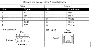
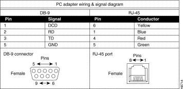
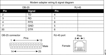
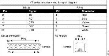
This guide also provides the following pin assignments:
The Catalyst 1800 console cable kit (part number 78-1188-01) includes
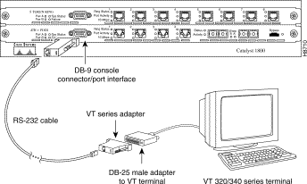
Follow these steps to connect a VT 320/420-series terminal to a Catalyst 1800 Token Ring switch (see Figure 1):
Step 1 Plug either end of the EIA/TIA-232 cable into the RJ-45-to-DB-9 female adapter labelled "Console port."
Step 2 Connect the console port female adapter to the male DB-9 console port on the front of the Catalyst 1800 chassis.
Step 3 Plug the RJ-45 connector at the other end of the EIA/TIA-232 cable into the RJ-45-to-DB-25 female adapter labelled "VT series."
Step 4 Connect the VT-series DB-25 female adapter to the DB-25 male adapter on the cable extending from the VT terminal's COMM port.
Step 5 Turn on the terminal and access the setup directory. Set the following parameters on your terminal:
Transmit | 9600 |
Bits per character (BPC) | 8 |
Parity | None |
Stop bit | 1 |
Flow control | Off |
After these parameters are set, you can access out-of-band management. Refer to the Catalyst 1800 Token Ring Switch User Guide for instructions on using the console interface.
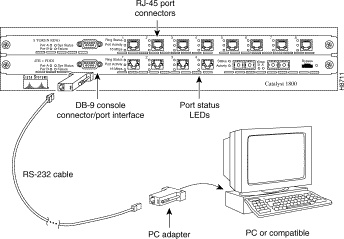
Follow these steps to connect an IBM PC or compatible to a Catalyst 1800 switch (see Figure 2). Note that the PC must be running a VT terminal emulation program.
Step 1 Plug either end of the EIA/TIA-232 cable into the RJ-45-to-DB-9 female adapter labelled "Console port."
Step 2 Connect the console port female adapter to the male DB-9 console port on the front of the Catalyst 1800 chassis.
Step 3 Plug the RJ-45 connector at the other end of the EIA/TIA-232 cable into the RJ-45-to-DB-9 female adapter labelled "PC."
Step 4 Connect the DB-9 female adapter to the appropriate male communications port on the PC.
Step 5 Turn on the PC and configure its VT emulation package with following parameters:
Transmit | 9600 |
Bits per character (BPC) | 8 |
Parity | None |
Stop bit | 1 |
Flow control | Off |
After these parameters are set, you can access out-of-band management. Refer to the Catalyst 1800 Token Ring Switch User Guide for instructions on using the console interface.
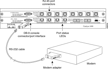
Follow these steps to connect an IBM PC or compatible to a Catalyst 1800 switch (see Figure 3). Note that the PC must be running a VT terminal emulation program.
Step 1 Plug either end of the EIA/TIA-232 cable into the RJ-45-to-DB-9 female adapter labelled "Console port."
Step 2 Connect the console port female adapter to the male DB-9 console port on the front of the Catalyst 1800 chassis.
Step 3 Plug the RJ-45 connector at the other end of the EIA/TIA-232 cable into the RJ-45-to-DB-25 male adapter labelled "Modem."
Step 4 Connect the DB-25 male adapter to the appropriate female communications port on the modem.
Step 5 Turn on the modem and configure its VT emulation package with following parameters:
Transmit | 9600 |
Bits per character (BPC) | 8 |
Parity | None |
Stop bit | 1 |
Flow control | Off |
After these parameters are set, you can access out-of-band management. Refer to the Catalyst 1800 Token Ring Switch User Guide for instructions on using the console interface.
Diagrams in this section provide wiring and signal information for the cable and adapters in the Catalyst 1800 console cable kit. 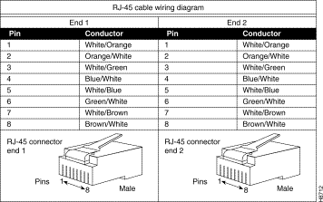
Cisco Connection Online (CCO) is Cisco Systems' primary, real-time support channel. Maintenance customers and partners can self-register on CCO to obtain additional information and services.
Available 24 hours a day, 7 days a week, CCO provides a wealth of standard and value-added services to Cisco's customers and business partners. CCO services include product information, user documentation, software updates, release notes, technical tips, the Bug Navigator, configuration notes, brochures, descriptions of service offerings, and download access to public and authorized files.
CCO serves a wide variety of users through two interfaces that are updated and enhanced simultaneously: a character-based version and a multimedia version that resides on the World Wide Web (WWW). The character-based CCO supports Zmodem, Kermit, Xmodem, FTP, and Internet e-mail, and it is excellent for quick access to information over lower bandwidths. The WWW version of CCO provides richly formatted documents with photographs, figures, graphics, and video, as well as hyperlinks to related information.
You can access CCO in the following ways:
For a copy of CCO's Frequently Asked Questions (FAQ), contact cco-help@cisco.com. For additional information, contact cco-team@cisco.com.

![]()
![]()
![]()
![]()
![]()
![]()
![]()
![]()
Posted: Sat Sep 28 01:18:20 PDT 2002
All contents are Copyright © 1992--2002 Cisco Systems, Inc. All rights reserved.
Important Notices and Privacy Statement.