|
|

Large Token Ring LANs are divided into smaller rings, typically by the use of bridges and routers, because the number of stations that can be connected to any single ring is limited.
Furthermore, since stations must contend for the token with other stations on the same ring, attaching fewer stations to a ring gives each one a greater number of opportunities to transmit and receive information.
The traditional method of connecting multiple Token Ring networks is by using a source-routing bridge. For example, bridges are often used to link workgroup rings to the backbone ring. However, the introduction of the bridge can significantly reduce performance at the user's workstation.
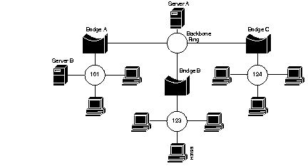
In Figure B-1, bridges B and C that connect local rings to the backbone ring reduce the performance of rings 123 and 024 that access Server A. Further problems may be introduced by aggregate traffic loading on the backbone ring.

To maintain performance and avoid overloading the backbone ring, you can locate servers on the same ring as the workgroup that needs to access the server. However, this makes the servers more difficult to back up, administer, and secure than if they are located on the backbone ring, and limits the number of servers that particular stations can access.
Collapsed backbone routers may offer greater bandwidth than bridges, and can interconnect a larger number of rings without becoming overloaded. However, routers are best suited to wide area network (WAN) environments, and are not the best solution for connecting Token Ring local area networks (LANs) together.
Routers introduce a delay, or latency, between receiving the first bit of a frame and transmitting the first bit on another port. This is because routers operate in store-and-forward mode, buffering each packet into memory before determining the destination of the frame.
The Catalyst 1600 Token Ring switch is a source-routing switch with multiple Token Ring ports that support the attachment of wiring concentrators and lobe stations.
The Catalyst 1600 Token Ring switch offers the following features:
As a local collapsed backbone device, the Catalyst 1600 Token Ring switch offers a lower per-port cost and incurs lower interstation latency than a router, and supports the direct connection of workstations and network servers. Alternatively, the Catalyst 1600 can be used in conjunction with a router, providing a high-capacity interconnection between Token Ring segments while retaining the wide-area connectivity provided by the router.
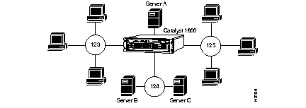
In Figure B-2, servers are located either on a single ring or are directly connected to the Catalyst 1600. Because the Catalyst 1600 has a greater internal capacity than 16 Mbps Token Ring, it can enable workgroups 123 and 125 to access the servers without becoming overloaded by traffic.

In addition, the Catalyst 1600 introduces minimal latency. Therefore, nodes can communicate with servers on another ring and deliver performance as if both were attached to the same ring.
This occurs because the Catalyst 1600 Token Ring switch performs the following:
The Catalyst 1600 Token Ring switch transfers nonbroadcast packets between rings without buffering the entire frame into memory. Instead, the Catalyst 1600 analyses the packet header and determines the destination of a packet when it has received the first few bytes of a frame. When the Catalyst 1600 has determined the destination, it establishes a connection between the input and output ports and, when the token becomes available, the Catalyst 1600 transmits the packet onto the destination ring.
In accordance with specification ISO/IEC 10038, the Catalyst 1600 Token Ring switch uses Access Priority 4 to gain priority access to the token on the output ring. This increases the proportion of packets that can be cut-through, and makes it possible for the Catalyst 1600 to reduce the average inter-station latency. However, in certain circumstances, the cut-through technique cannot be applied and the Catalyst must buffer packets into memory.
For example, buffering must be performed when:
The Catalyst 1600 Token Ring switch uses source-routing information to resolve forwarding decisions. Source routing requires clients to establish a route using a discovery process, and then include the information that defines the route in each packet that they send. Because the source-routing information defines the ring to which the packet is passed, the Catalyst 1600 Token Ring switch can forward packets with minimal processing.
Figure B-3 shows how source-routing broadcast packets contain information that identifies the ring on which the packet originates. Therefore, switching by source routing also facilitates port blocking and broadcast filtering, which allows you to implement broadcast control strategies by configuring virtual LANs that span multiple Catalyst 1600 devices.

For information about controlling broadcast frames by defining virtual LANs, refer to TrueView Catalyst 1600 Manager User Guide.
When the Catalyst 1600 Token Ring switch receives the first few bytes of a packet, it analyses the routing information field (RIF) in the frame header. The Catalyst 1600 determines whether the frame is source routed, and if it is not, the frame is ignored.
The Catalyst 1600 forwards source-routed frames according to the forwarding decision process described in Table B-1.
Like source-routing bridges, the Catalyst 1600 can use the IEEE spanning tree algorithm to determine the best path for frames when there are multiple path routes in an internetwork. This algorithm determines which bridge forwards single-route broadcast frames onto each ring and ensures that no single-route broadcast frames appear more than once on the same ring.
|
|