|
|

Table Of Contents
Quick Reference
Catalyst 8540 CSR and MSR
Hardware InformationDistance and Pinout Information
Regulatory and Compliance Information
Quick Reference
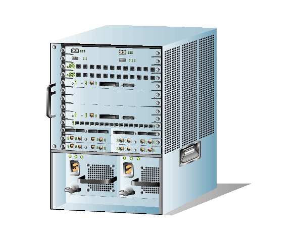
Catalyst 8540 CSR and MSR
Hardware Information
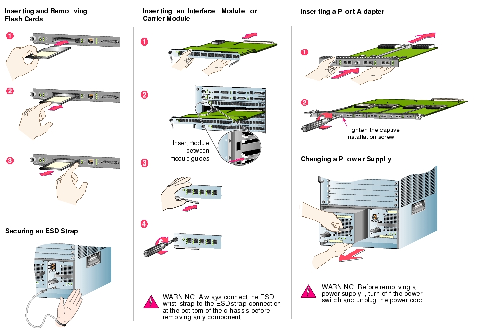
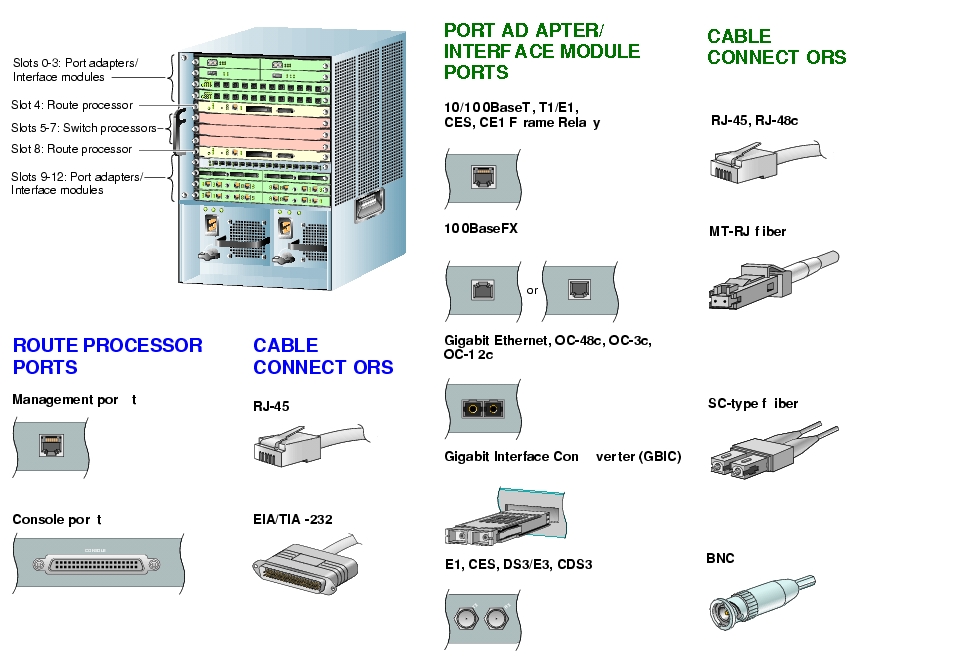
Ports and Cabling
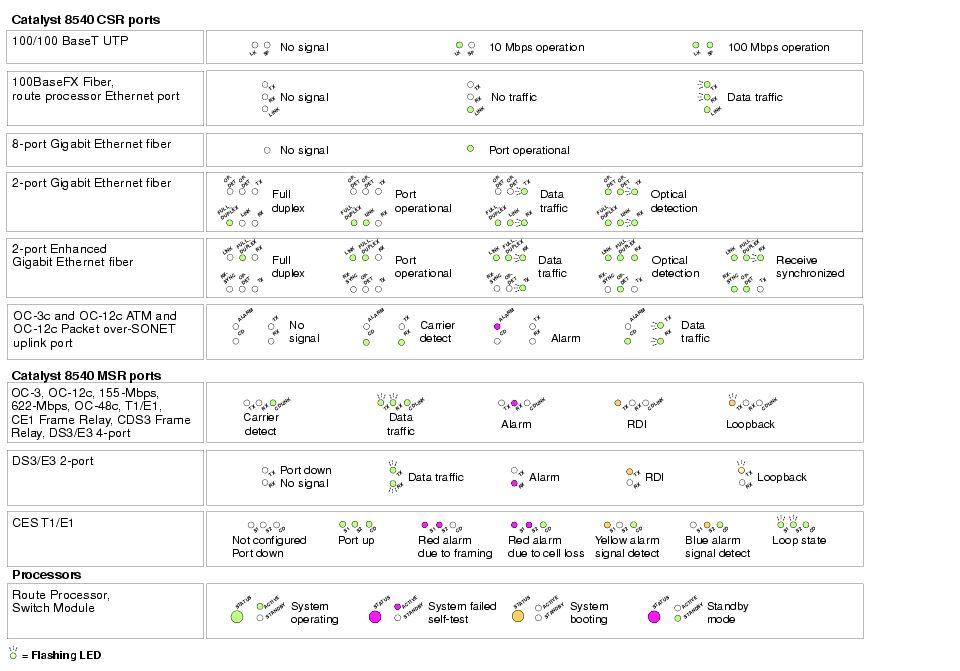
LEDs and Troubleshooting
Distance and Pinout Information
Maximum Transmission Distances
10/100-Mbps Ethernet
Category 5 UTP
328 feet (100 m)
100-Mbps Ethernet
Multimode fiber
1640 feet (500 m)
1000-Mbps Ethernet
Multimode fiber
1640 feet (500 m)
1000-Mbps Ethernet
Single-mode fiber
16404 feet (5 km)
OC-3c, 155-Mbps ATM
Single-mode fiber
9 miles (15 km)
OC-3c, 155-Mbps ATM
Single-mode fiber, long reach
18 miles (30 km)
OC-3c, 155-Mbps ATM
Multimode fiber
1.2 miles (2 km)
OC-12c, 622-Mbps
Single-mode fiber, intermediate reach
9 miles (15 km)
OC-12c, 622-Mbps
Single-mode fiber, long reach
25 miles (40 km)1
OC-12c, 622-Mbps
Multimode fiber
1640 feet (500 m)
OC-48c, 2488-Mbps
Single-mode fiber, intermediate reach
9 miles (15 km)
OC-48c, 2488-Mbps
Single-mode fiber, long reach
50 miles (80 km)
T1, 1.544-Mbps ATM
Category 5 twisted-pair
650 feet (198 m)
E1, 2.048-Mbps ATM
Category 5 twisted-pair and FTP (120 ohm)
650 feet (198 m)
E1, 2.048-Mbps ATM
Coaxial cable (75 ohm)
650 feet (198 m)
CE1, 2.048-Mbps ATM
Category 5 twisted-pair
650 feet (198 m)
CES T1
Category 5 twisted-pair and FTP
650 feet (198 m)
CES E1
Category 5 twisted-pair and FTP (120 ohm)
820 feet (248.5 m)
CES E1
Coaxial cable (75 ohm)
650 feet (198 m)
DS3, 45-Mbps
Coaxial cable
450 feet (137 m)
E3, 34-Mbps
Coaxial cable
1299 feet (296 m)
CDS3, 45-Mbps
Coaxial cable
450 feet (137 m)
1 If you are attaching a short cable to the 622-Mbps long-reach port adapter, you must add 10 dB of attenuation to the cable or the transmitter might overdrive the receiver and introduce data errors.
Pinouts to RJ-45 Connectors
The 10/100 Mbps Ethernet interface module with unshielded twisted-pair (UTP) ports supports RJ-45 connectors. The following table lists the signals for RJ-45 cable connectors.
1
RxD+
Receive data +
2
RxD-
Receive data -
3
NC
No connection
4
NC
No connection
5
NC
No connection
6
NC
No connection
7
TxD+
Transmit data +
8
TxD-
Transmit data -
Pinouts to RJ-48c Connectors
The T1, E1, T1 CES and E1 port adapters support RJ-48c connectors. The following table lists the signals for RJ-48c connectors.
1
Receive ring
2
Receive tip
3
No connection
4
Transmit ring
5
Transmit tip
6
No connection
7
No connection
8
No connection
Regulatory and Compliance Information
Specifications
The following table lists the specifications for the Catalyst 8540.
.
DOC-786274=
78-6274-02
![]()
![]()
![]()
![]()
![]()
![]()
![]()
![]()
Posted: Mon Mar 1 00:00:18 PST 2004
All contents are Copyright © 1992--2004 Cisco Systems, Inc. All rights reserved.
Important Notices and Privacy Statement.