|
|

This chapter describes how to install Micro Webserver and verify that it is functioning correctly.
Topics included in this chapter are:
In order to install Micro Webserver on your network, you need the following items:
This section describes some basic safety procedures for working with your Micro Webserver. Also refer to the Regulatory Compliance and Safety Information for the Cisco Micro Webserver (Document number 78-4015-01).
Follow these guidelines to ensure general safety:
 | Warning There is the danger of explosion if the battery is replaced incorrectly. Replace the battery only with the same or equivalent type recommended by the manufacturer. Dispose of used batteries according to the manufacturer's instructions. |
 | Warning Only trained and qualified personnel should be allowed to install or replace this equipment. |
Follow these guidelines when working on equipment powered by electricity:
 | Warning Before working on a system that has an on/off switch, turn OFF power cord. |
 | Warning Do not work on the system or connect or disconnect cables during periods of lightning activity. |
 | Warning Ultimate disposal of this product should be handled according to all national laws and regulations. |
Electrostatic discharge (ESD) can damage equipment and impair electrical circuitry. ESD damage occurs when electronic components are improperly handled and can result in complete or intermittent failures.
This section describes the requirements your site must meet for safe installation and operation of your system. Ensure that your site is properly prepared before beginning installation.
The Micro Webserver can be placed on a desktop or mounted in a rack. The location of the Micro Webserver and the layout of your equipment rack or wiring room are extremely important for proper system operation. Equipment placed too close together, inadequate ventilation, and inaccessible panels can cause system malfunctions and shutdowns, and can make Micro Webserver maintenance difficult.
When planning your site layout and equipment locations, keep in mind the precautions described in the next section, "Preventive Site Configuration," to help avoid equipment failures and reduce the possibility of environmentally caused shutdowns. If you are currently experiencing shutdowns or unusually high errors with your existing equipment, these precautions may help you isolate the cause of failures and prevent future problems.
The following precautions will help you plan an acceptable operating environment for your Micro Webserver and will help you avoid environmentally caused equipment failures:
Remove the Micro Webserver from its shipping container. You should have the following items:
This section describes how to quickly install your Micro Webserver using the BOOTP server program provided. This section assumes that you are on the same IP subnet segment and any routers between you and the Micro Webserver are configured to allow BOOTP. These are condensed instructions for those comfortable with quick install procedures. If you are not comfortable with simplified procedures, or the BOOTP utility does not function correctly on your network, refer to the sections, "Installing the Software Utilities" to install the software and "Connecting Micro Webserver" to connect the hardware.
 | Warning Do not touch the power supply when the power cord is connected. For systems with a power switch, line voltages are present within the power supply even when the power switch is off and the power cord is connected. For systems without a power switch, line voltages are present within the power supply when the power cord is connected. |
 | Warning Read the installation instructions before you connect the system to its power source. |
 | Warning This product relies on the building's installation for short-circuit (overcurrent) protection. Ensure that a fuse or circuit breaker no larger than 120 VAC, 15A U.S. (240 VAC, 10A international) is used on the phase conductors (all current-carrying conductors). |
 | Warning The Ethernet 10BaseT, serial, console, and auxiliary ports contain safety extra-low voltage (SELV) circuits. PRI circuits are treated like telephone-network voltage (TNV) circuits. Avoid connecting SELV circuits to TNV circuits. |
 | Warning The device is designed to work with TN power systems. |
 | Warning This equipment is intended to be grounded. Ensure that the host is connected to earth ground during normal use. |
 | Warning Before working on equipment that is connected to power lines, remove jewelry (including rings, necklaces, and watches). Metal objects will heat up when connected to power and ground and can cause serious burns or weld the metal object to the terminals. |
This section is for users running Windows 95 or Windows NT 4.x.
Step 1 Connect your Ethernet RJ-45 connector to the receptacle labeled "Ethernet."
Step 2 Connect the DC power end of the AC adapter to the receptacle labeled "Power."
Step 3 Plug the other end of the AC adapter into the AC power source. Do not power on the Micro Webserver.
Step 4 Verify that the rear-panel SCSI switch (closest serial port) is up and S/W (closest to Ethernet port) is down (and no SCSI devices are connected).
Step 5 Install the system software as described in the section, "Installing the Software Utilities".
Step 6 Run the BOOTP utility by selecting it from the Cisco Micro Webserver program group accessed through the Start menu. The main BOOTP window appears: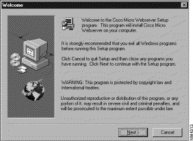
Step 7 Click Add. The Bootp Table Editor edit box appears: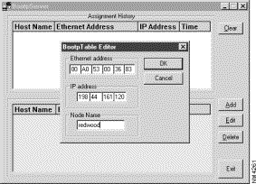
Step 8 Enter the Ethernet address from the bottom of your Micro Webserver.
Step 9 Enter the desired IP address assigned by your system administrator.
Step 10 Enter a name for the server in the Node Name field.
Step 11 Click OK. The entry is added to the Bootp Table list: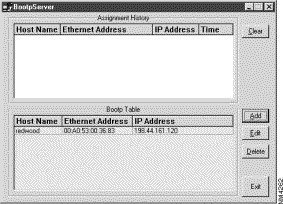
Step 12 Turn the power switch on the rear of the Micro Webserver to the On (up) position.
Step 13 After a few seconds, the entry from the Bootp Table appears in the Assignment History table. This indicates that the server has received the IP address: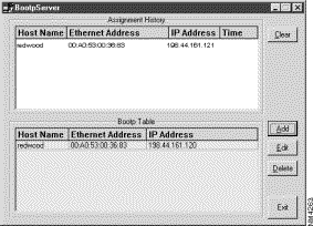
Step 1 Connect your network Ethernet RJ-45 connector to the receptacle labeled "Ethernet."
Step 2 Connect the DC power end of the AC adapter to the receptacle labeled "Power."
Step 3 Plug the other end of the AC adapter into the AC power source.
Step 4 Ensure that switch 1 (closest to serial Port) is up and switch 2 (closest to Ethernet) is down.
Step 5 Turn the power switch on the rear of the Micro Webserver to the On (up) position.
Step 6 Connect a nine-pin serial null modem cable to the Micro Webserver and your workstation or terminal.
Step 7 Run a terminal emulation program (such as HyperTerm provided with Windows 95).
Step 8 Set the comm port to 9600,n,8,1 with no flow control.
Step 9 Log into your Micro Webserver using root as the User Name. By default, no password is necessary.
Step 10 Set the IP address. If your IP address is 198.44.161.120, at the command prompt enter:
config nvram internet-address 198.44.161.120
Step 11 Set the default gateway. If your default gateway is 198.44.161.1, at the command prompt enter:
config nvram default-gateway 198.44.161.1
Step 12 Set the subnet mask. If your subnet mask is 255.255.255.0, at the command prompt enter:
config nvram netmask 255.255.255.0
Step 13 Write the changes to memory. At the command prompt enter:
config nvram write
Step 14 Reboot the Micro Webserver. At the command prompt enter:
reboot
Step 1 Using your browser, enter the IP address in the location field using http protocol.
Example: http://191.44.161.120
Step 2 Press Enter.
Step 3 The Cisco Micro Webserver Home Page appears:
Step 4 Select the configure icon. The Configuration application (and Login tab) appears: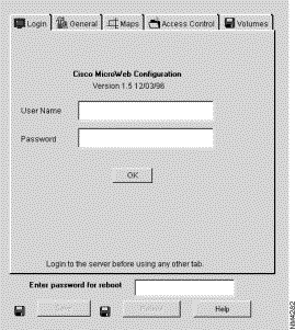
Step 5 Enter root in the User Name field. No password is required.
Step 6 Click OK. The General tabs appear.
Step 7 Select the Basic tab. The Basic tab appears: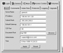
Step 8 Complete all of the fields with the appropriate information.
Step 9 Select the Save tab and click Save.
Your Micro Webserver is now functional. You can refer to the online documentation to help you administer your site.
This section describes how to install the File Transfer Utility, Form Builder application and BOOTP server software on the 3.5" diskettes included with your Micro Webserver. This section only applies to Windows 95 and Windows NT 4.x users.
Step 1 Place the 3.5" diskette labeled "Disk 1 of 2" in the a: drive of your workstation.
Step 2 From the Windows 95 Start menu, select Run.
Step 3 The Run dialog appears:
Step 4 Enter a:setup in the Open field.
Step 5 Click OK. The Welcome dialog appears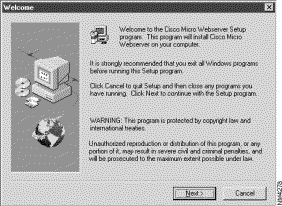 :
:
Step 6 Click Next. The Choose Destination Location dialog appears: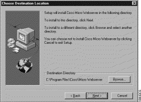
Step 7 You can accept the recommended Destination Directory or browse to select the location by choosing Browse.
Step 8 When the Destination Directory field is acceptable, click Next. The Select Program Folder dialog appears: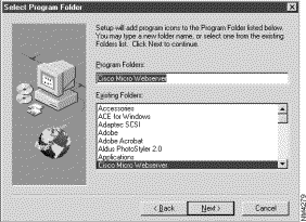
Step 9 Accept the recommended folder, select a folder name from the Existing Folders list, or enter a new name in the Program Folders field.
Step 10 Click Next. The files are then copied to your workstation drive. After the files are copied, the Setup Complete dialog appears: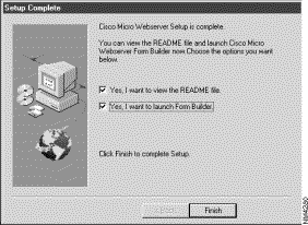
Step 11 Check or clear the appropriate check box to view the readme file and/or run the Form Builder application.
Step 12 Click Finish. The software is installed on your workstation.
This section describes more explicitly what you need to do to connect the Micro Webserver to your network and power source.
Remove the Micro Webserver from its shipping container and place it on a flat surface. Connect Micro Webserver's 10BaseT (UTP) port located on the back panel as shown below to an active 10BaseT HUB port using a standard straight-through 10BaseT cable. 
The switch settings on the Micro Webserver do not need to be changed from the default mode except to manually download new parameters or to add additional SCSI devices such as CD-ROM drives.
The following table describes the switches and their function.
| SCSI | S/W | Description |
|---|---|---|
down | down | external SCSI devices, normal operating mode |
down | up | external SCSI devices, manual firmware update mode |
up | down | Default. No external SCSI devices, normal operating mode |
up | up | No external SCSI devices, manual firmware update mode |
You may need to reset the parameters stored in NVRAM to the factory default states. Once an IP address is set, you must reset the firmware to use the BOOTP server program. To reset the firmware, follow the procedure below.
 | Caution Resetting the firmware will cause you to lose all data previously set in the configuration NVRAM. |
Step 1 Place the S/W switch UP (the switch that is most distant from the SCSI connector).
Step 2 Power on the Micro Webserver. The yellow Ethernet LED in the back flashes on and off, and the front LED flashes from green to red.
While these LEDs are flashing, put the S/W switch down (i.e., return it to its original position).
You have about 10 seconds to place the S/W switch down, or the system boots normally, and the procedure must be restarted from step 1.
Step 3 The LEDs stop flashing. You are now running the FLUP (Flash Update Program) program (the system is listening for a serial or TFTP download of new firmware).
Step 4 Toggle the S/W switch 12 times (6 up + 6 down) or more.
Step 5 The NVRAM data is cleared. An informational message to this effect appears on the serial line, although a serial device is not needed to run this procedure.
Step 6 Place the S/W switch in the down position.
Step 7 Power the Micro Webserver off and on to reboot with cleared NVRAM. The IP address is now set to 0.0.0.0 and BOOTP is enabled.
TCP/IP devices require that all IP addresses be unique. This section covers a variety of procedures for setting the IP address of Micro Webserver. It is usually not necessary to set a default gateway or net mask (even if you have gateways on your network), because Micro Webserver will use ARP (Address Resolution Protocol) information to accomplish routing when no default gateway is set. However, if you need to set these parameters, see the chapter "Configuring Micro Webserver".
Determine the Ethernet address of your Micro Webserver by reading it from the product label on the bottom of the Micro Webserver. The format of the Ethernet address is similar to 00:A0:53:hh:hh:hh.
For the following examples, webserver1 will be used as a sample host name. You can set the name to whatever is agreed upon between you and the network administrator.
You should assign a unique IP address for Micro Webserver. For this document, the address is represented by: ddd.ddd.ddd.ddd. If you are not sure of the available IP addresses, contact your network administrator.
Although the IP address is a single (4-part) number, it is internally divided into a network part and a host part. The Micro Webserver's Internet address must match the network part of other hosts on the network and its host part must be unique among these hosts. Typically, this means that the first 3 parts of the IP address match all other hosts on the local Ethernet and the 4th part is unique.
There are several ways to accomplish IP address assignment; choose the one that is easiest for you to use.
Using Windows Explorer or File Manager, run the BOOTP program as described in the section, "Installing Micro Webserver Using the BOOTP Utility" .
Alternately, you can use your own BOOTP server. Follow the instructions for your particular BOOTP server. A typical example is:
BSD BOOTP Daemon

webserver1:ht=Ethernet:ha=00a053hhhhhh:

ip=ddd.ddd.ddd.ddd:

where: 00a053hhhhhh is the Ethernet address and ddd.ddd.ddd.ddd is
the IP address.
where 00a53hhhhhh is the ethernet address and ddd.ddd.ddd.ddd is the IP address.
If you wish to configure Micro Webserver using a serial console or terminal emulation program:
Step 1 Connect the serial port on the 9-pin "D" connector on the rear panel of the Micro Webserver to a serial port on your workstation or terminal using a null modem serial cable.
The following table summarizes the pinout of the null modem cable.
| Micro Webserver DB9 Female | Cable Connections | PC Com1/Laptop DB9 Female | PC Com2/UNIX DB25 Female |
|---|---|---|---|
1DCD | N/C | 1 DCD | 8 |
2 RX | | 3 TX | 3 |
3 TX | | 2RX | 2 |
4 DTR | N/C | 4 DTR | 20 |
5 GND | | 5 GND | 7 |
6 DSR | N/C | 6 DSR | 6 |
7 RTS | | 8 CTS | 5 |
8 CTS | | 7 RTS | 4 |
9 RING | N/C | 9 RING | 22 |
Step 2 Log in to your Micro Webserver as root. By default, no password is necessary.
Step 3 Set the IP address. At the command prompt enter:
config nvram internet-address ddd.ddd.ddd.ddd
where ddd.ddd.ddd.ddd is the IP address.
Step 4 Write the IP address to memory. At the command prompt enter:
config nvram write
Step 5 Reboot the Micro Webserver. At the command prompt enter:
reboot <Y>
If your network has a RARP server in continuous operation, the IP address can be automatically assigned the first time Micro Webserver boots. To use this approach, insert an entry for Micro Webserver in both your Host and Ethernet tables.
Step 1 Add Micro Webserver's IP address and host name to the /etc/hosts file:
ddd.ddd.ddd.ddd webserver1
where ddd.ddd.ddd.ddd is the IP address of the Micro Webserver and webserver1 is the host name.
Step 2 Add Micro Webserver's host name and Ethernet address to the /etc/ethers file:
webserver1 ddd.ddd.ddd.ddd
where hh:hh:hh:hh:hh:hh is the Ethernet address from the bottom of the Micro Webserver.
Step 3 Power up Micro Webserver on your network. Micro Webserver automatically initializes itself.
From a UNIX host, proceed as follows:
Step 1 Add your Micro Webserver to the /etc/hosts file:
webserver1 ddd.ddd.ddd.ddd
where ddd.ddd.ddd.ddd is the IP address of the Micro Webserver.
Step 2 Use the arp -s command to set a static arp entry:
arp -s webserver1 hh:hh:hh:hh:hh:hh
where hh:hh:hh:hh:hh:hh is the Ethernet address from the bottom of the Micro Webserver.
Step 3 Telnet to your Micro Webserver using port 2000. Username default is root. No password is necessary:
telnet webserver1 2000
The IP address is now set in RAM.
Step 4 At the login prompt, log in as root.
Step 5 At the command prompt enter:
config nvram internet-address ddd.ddd.ddd.ddd
where ddd.ddd.ddd.ddd is the IP address.
Step 6 At the command prompt enter:
config nvram write
Step 7 At the command prompt enter:
reboot <Y>
You are ready to use Micro Webserver. Refer to the chapter, "Configuring Micro Webserver" to complete the configuration process if you are not adding additional SCSI devices such as CD-ROMs or external drives.
You can now ping your server using any TCP/IP Ping utility. For example, if your server is set to 191.168.240.120, enter:
ping 191.168.240.120
If you get an error message, try pinging another accessible host. If you can ping the other host but not the Micro Webserver, verify that all cables are connected and that you have correctly installed the Micro Webserver. If the problem persists, contact your vendor.
Micro Webserver is capable of reading and writing to devices with a valid, non-conflicting SCSI ID number. Use only high-quality twisted-pair shielded cables to attach devices. To connect additional devices:
Step 1 Power off the Micro Webserver.
Step 2 Switch SCSI (closest to serial port) on the rear panel to the down position.
Step 3 Connect a SCSI cable to the SCSI cable port located on the rear panel of the Micro Webserver unit.
Step 4 Attach the cable to your first SCSI CD-ROM drive. The last drive in the string requires a singled-ended SCSI terminator unless it is internally terminated.
Step 5 Set the SCSI ID of the external devices.
Step 6 Power on the Micro Webserver.
Micro Webserver is the initiator in the SCSI string and uses ID-7. One to five SCSI CD-ROM drives are supported and they can be set as ID-0 or ID-2 through ID-6 (not ID-1 or ID-7) in any order in the string. Additionally, a SCSI drive of up to 1.2 GB can be accessed.
You are ready to use Micro Webserver. Refer to the chapter "Configuring Micro Webserver" to complete the configuration process.
![]()
![]()
![]()
![]()
![]()
![]()
![]()
![]()
Posted: Tue Dec 17 19:09:20 PST 2002
All contents are Copyright © 1992--2002 Cisco Systems, Inc. All rights reserved.
Important Notices and Privacy Statement.