|
|

This chapter describes the procedures for installing and configuring LocalDirector and includes the following sections:
Follow these guidelines to ensure general safety:
Check the shipping container to ensure all components are present before installing LocalDirector. The LocalDirector shipping container contains the following pieces:
Follow this procedure to install LocalDirector:
Step 1 Unpack LocalDirector and place it in your equipment rack or on a level surface.
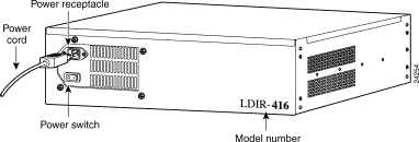
Step 2 On the back panel, connect the power cord to the LocalDirector power receptacle and plug the other end into a power source (see Figure 4-1).
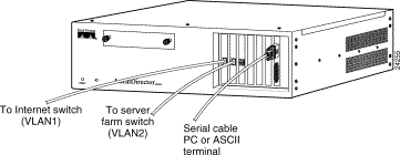
Step 3 On the front panel (see Figure 4-2), connect the following cables:
(a) Connect one end of the null modem serial cable to the LocalDirector
DB-9 console port and the other end to your ASCII terminal or computer. Use the DB-25 gender adapter, if necessary.
(b) Connect the network cable from the router or switch on the Internet side of your network (VLAN1) to a LocalDirector network interface connection.
(c) Connect the network cable of the hub or switch that is connected to the server farm (VLAN2) to another LocalDirector network interface connection.
Step 4 Configure the serial port for your computer or terminal with these settings:
9600 baud, 8 data bits, no parity, and 1 stop bit; that is, set 9600, 8-N-1. Ensure your communications software is running.
This section describes just the basic configuration for LocalDirector and the server farm.
Configuration for LocalDirector includes setting its IP address, testing a connection to the network, and setting a password. Configuration for the server farm includes defining virtual servers and real servers, setting the load-balancing and redirection options, binding virtual servers and real servers, and putting all servers into service. After configuration is complete, the example shows how to check your configuration and save it to memory.
Once basic configuration is complete, see the "Configuration Examples" section for additional procedures that can be used to set up specific LocalDirector features for your site.
Follow this procedure to configure LocalDirector system settings (basic configuration):
Step 1 Apply power to the LocalDirector (see Figure 4-1).
Because LocalDirector ships with its software loaded in Flash memory, LocalDirector boots without a system diskette.
As LocalDirector boots, messages such as the following appear:
Finesse Bios V3.3
Booting Floppy
Loading from Flash
32MB RAM
Flash=AT29C040A @ 0x300
 i82557 rev 2 Ethernet @ irq11 dev 13 index  0 MAC: 00a0.c965.576f
 i82557 rev 2 Ethernet @ irq15 dev 14 index  1 MAC: 00a0.c965.5b33
 i82557 rev 2 Ethernet @ irq 5 dev 15 index  2 MAC: 00a0.c965.56c1

LocalDirector 410 Version 3.x Initialization.....done.
Copyright (c) 1998 by Cisco Systems, Inc.

        Restricted Rights Legend

Use, duplication, or disclosure by the Government is
subject to restrictions as set forth in subparagraph
(c) of the Commercial Computer Software - Restricted
Rights clause at FAR sec. 52.227-19 and subparagraph
(c) (1) (ii) of the Rights in Technical Data and Computer
Software clause at DFARS sec. 252.227-7013.

        Cisco Systems, Inc.
        170 West Tasman Drive
        San Jose, California 95134-1706
Step 2 Use the enable command to access privileged mode.
Step 3 Use the configuration terminal command to access LocalDirector configuration commands.
Step 4 Use the ip address command to assign the LocalDirector IP address and subnet mask.
Step 5 Use the ping command to determine if LocalDirector has connectivity or if a host is available on the network. If this test fails, try the following:
Step 6 Use the enable password command to change the privileged mode password.
Step 7 If preferred, use the hostname command to change the host name for the LocalDirector command line prompt. Note that in a failover configuration, both units have the same host name because the configuration is copied from one unit to the other.
Follow this procedure to configure the LocalDirector server farm (secondary configuration):
Step 1 Use the virtual command to define virtual servers.
Step 2 If preferred, use the redirection command to change the default directed mode (Network Address Translation) to dispatched mode for the virtual servers. Additionally, use the alias ip address command to specify the virtual IP address on each real server that uses dispatched mode.
Step 3 Use the predictor command to set the type of load balancing for each virtual server.
Step 4 Use the real command to define real servers.
Step 5 Use the bind command to associate each virtual server to a real server.
Step 6 Use the in-service command to designate real servers and virtual servers as
in-service. (This can also be done when the virtual servers and real servers are defined.)
Step 7 Use the write terminal, show real, show virtual, and show bind commands to check the configuration.
Step 8 Use the write memory command to store the configuration in Flash memory.
Step 9 Use the show config command to verify the configuration stored in Flash memory.
The basic configuration is complete. Exit configuration mode by entering ^Z, and exit privileged mode with the disable command.
Figure 4-3 shows an example of a basic configuration with one virtual server bound to two real servers.

To help determine virtual and real server configurations, diagram the implementation before you begin. Ensure that any virtual IP address you configure is from a valid IP network. If the virtual address is to be accessed from the Internet, the IP address must be part of a Network Information Center-allocated network number.
This section provides example server configurations in the following sections:
Table 4-1 shows LocalDirector default configuration settings.
| Configuration Setting | Default Value | Minimum Value | Maximum Value |
|---|---|---|---|
Redirection mode | Directed, local | --- | --- |
IP services | TCP enabled on virtual and real servers | --- | --- |
SYSLOG console | Not defined | --- | --- |
Routing Information Protocol (RIP) | Disabled | --- | --- |
Timeout value | 120 minutes | 5 minutes | 65,535 minutes (45.5 days) |
Sticky value | 0 (disabled) | 0 minutes | 65,535 minutes (45.5 days) |
Reassign value | 3 | 1 | 4 |
Threshold value | 8 | 0 | 65,535 |
Retry value | 1 minute | 0 | 65,535 minutes (45.5 days) |
Predictor | Leastconns | --- | --- |
Weight value | 1 | 0 | 65,535 |
Autounfail | On | --- | --- |
Slowstart option | Roundrobin | --- | --- |
Bridging | Allowed | --- | --- |
Maximum connections | 0 (unlimited) | --- | --- |
Synguard protection | 0 (off) | --- | --- |
Data connections | 0 (off) | --- | --- |
In this example, LocalDirector is load balancing all TCP traffic over two servers to provide Web services. Figure 4-4 shows the network configuration.
All traffic destined for virtual IP address 192.168.1.99 is load balanced across real servers with IP addresses 192.168.1.1 and 192.168.1.2. Only the virtual server appears in the Domain Name System (DNS). Follow this procedure to set up this configuration:
Step 1 Use the enable command to enter privileged mode. Type a carriage return at the password prompt if you do not want to assign a privileged password:
LocalDirector# enable
Password:<CR>
Step 2 Use the configuration t command to enter configuration mode:
LocalDirector# configuration t
Step 3 Use the ip address command to specify LocalDirector IP address 192.168.1.89, and subnet mask 255.255.255.0:
ld(config) 1# ip address 192.168.1.89 255.255.255.0
Step 4 Use the interface ethernet command with the auto option (if your interface card supports this option) to automatically set the speed of the Ethernet interface:
ld(config) 2# interface ethernet 0 auto
ld(config) 3# interface ethernet 1 auto
Otherwise, use the interface ethernet command with the option that is appropriate for your card to set the speed manually:
ld(config) 2# interface ethernet 0 [10baset|100basetx|100full]
Step 5 Use the shutdown command to disable unused interface ports:
ld(config) 4# shutdown interface ethernet 2
ld(config) 4# shutdown interface ethernet 3
Step 6 Use the name command to identify 192.168.1.99 as domain, and the virtual command to define domain as a virtual server:
ld(config) 5# name 192.168.1.99 domain
ld(config) 6# virtual domain
Step 7 Use the name command to identify IP address 192.168.1.1 as server 1 and 192.168.1.2 as server 2:
ld(config) 7# name 192.168.1.1 server1
ld(config) 8# name 192.168.1.2 server2
Step 8 Use the real command to identify server 1 and server 2 as real servers, and the is (in-service) option to enable the real servers to start accepting connections:
ld(config) 9# real server1 is
ld(config) 0# real server2 is
Step 9 Use the bind command to associate domain with server 1 and server 2 and establish the load-balancing relationship between the virtual and real servers:
ld(config) 1# bind domain server1 server2
Step 10 Use the is command to bring the virtual server into service:
ld(config) 2# is virtual domain
Step 11 Use the write terminal command to view the running configuration before it is saved.
Step 12 Use the write mem command to save the new settings:
ld(config) 3# write mem
Building configuration...
[OK]
Step 13 View the saved configuration with the show configuration command:
ld(config)# show configuration
: Saved
: LocalDirector 420 Version 3.1.0.106
syslog output 20.3
no syslog console
enable password dfeaf10390e560aea745ccba53e044 encrypted
hostname localdirector
no shutdown ethernet 0
no shutdown ethernet 1
shutdown ethernet 2
shutdown ethernet 3
interface ethernet 0 100basetx
interface ethernet 1 100basetx
interface ethernet 2 100basetx
interface ethernet 3 100basetx
mtu 0 1500
mtu 1 1500
mtu 2 1500
mtu 3 1500
multiring all
no secure  0
no secure  1
no secure  2
no secure  3
ping-allow 0
ping-allow 1
ping-allow 2
ping-allow 3
ip address 192.168.1.89 255.255.255.0
route 0.0.0.0 0.0.0.0 172.20.30.1 1
no rip passive
failover ip address 0.0.0.0
no failover
password cisco
no snmp-server contact
no snmp-server location
casa service-manager port 1638
virtual 192.168.1.99:0:0:tcp is
real 192.168.1.2:0:0:tcp is
real 192.168.1.1:0:0:tcp is
name 192.168.1.1 server1
name 192.168.1.2 server2
name 192.168.1.99 domain
bind 192.168.1.99:0:0:tcp 192.168.1.2:0:0:tcp
bind 192.168.1.99:0:0:tcp 192.168.1.1:0:0:tcp
localdirector(config)#
In this example, four virtual addresses are bound to a single Web server, as shown in Figure 4-5, allowing you to provide multiple DNS entries for one server. In other words, one real server supports multiple domain names. Virtual IP addresses 192.168.1.99, 192.168.1.100, 192.168.1.101, and 192.168.1.102 are identified as domain 1, domain 2, domain 3, and domain 4, respectively. Port 80 traffic for each virtual IP address is bound to different ports on real server IP 192.168.1.2.
All Web traffic destined for domain 1 accesses information on real server 192.168.1.2 through port 8000. Traffic destined for domain 2 accesses information on real server 192.168.1.2 through port 8001, and so on.
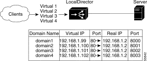
Also, by defining a virtual server as an IP address and a port, you can restrict traffic to a specific port. Port 80 is specified for each of the virtual servers, and ports 8000, 8001, 8002, and 8003 are specified for the real server. The virtual server ports and real server ports are bound to each other directly with a unique bind-id on the real server for each port that is bound. In addition, if the application running on port 8000 fails, the entire server is not failed by LocalDirector; the remaining ports continue to accept connections.
Follow this procedure to configure multiple virtual servers for one real server:
Step 1 Use the name command to identify the IP addresses of the virtual and real servers:
ld(config)# name 192.168.1.99 domain1
ld(config)# name 192.168.1.100 domain2
ld(config)# name 192.168.1.101 domain3
ld(config)# name 192.168.1.102 domain4
ld(config)# name 192.168.1.2 server
Step 2 Use the real command to identify the IP address named server as the real server that is accepting connections on ports 8000, 8001, 8002, and 8003:
ld(config)# real server:8000
ld(config)# real server:8001
ld(config)# real server:8002
ld(config)# real server:8003
Step 3 Use the virtual command to identify the named IP addresses domain 1, domain 2, domain 3, and domain 4 as virtual servers accepting connections on port 80:
ld(config)# virtual domain1:80
ld(config)# virtual domain2:80
ld(config)# virtual domain3:80
ld(config)# virtual domain4:80
Step 4 Use the bind command to direct port 80 network traffic from each virtual server to a different port on the real server:
ld(config)# bind domain1:80 server:8000
ld(config)# bind domain2:80 server:8001
ld(config)# bind domain3:80 server:8002
ld(config)# bind domain4:80 server:8003
Step 5 Use the is real command to set the service state for all real server ports to
in service:
ld(config)# is real server:8001
ld(config)# is real server:8002
ld(config)# is real server:8003
ld(config)# is real server:8000
Step 6 Use the is virtual command to set the service state for all virtual server ports to in service:
ld(config)# is virtual domain1:80
ld(config)# is virtual domain2:80
ld(config)# is virtual domain3:80
ld(config)# is virtual domain4:80
Step 7 Use the show bind command to display the association between the virtual server ports and real server ports:
ld(config)# show bind

       Virtual Machine(s)        Real Machines
         domain2:80:0:tcp(IS)
                                  server:8001:0:tcp(IS)
         domain1:80:0:tcp(IS)
                                  server:8000:0:tcp(IS)
         domain4:80:0:tcp(IS)
                                  server:8003:0:tcp(IS)
         domain3:80:0:tcp(IS)
                                  server:8002:0:tcp(IS)
ld(config)#
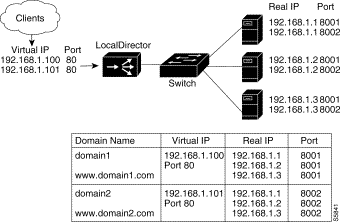
You can combine multiple virtual servers and multiple real servers so that each virtual server sends network traffic to the same port across real servers, as shown in Figure 4-6. All TCP traffic destined for virtual server 192.168.1.100 is load balanced across the three real servers on port 8001. Traffic destined for virtual server 192.168.1.101 is load balanced across the real servers on port 8002.
A combination of virtual servers and real servers can also be used to load balance traffic across server clusters, as shown in Figure 4-7.
Each virtual server can have a different load balancing option set with the predictor command. For example, 192.168.1.100 can be configured to use the leastconns option, and 192.168.1.101 can be configured to use the weighted option.
Follow this procedure to configure multiple virtual servers for multiple real servers:
Step 1 Use the real command to identify three real servers, each accepting connections on ports 8001 and 8002. Use the is option to put the real servers in service:
ld(config)# real 192.168.1.1:8001 is
ld(config)# real 192.168.1.1:8002 is
ld(config)# real 192.168.1.2:8001 is
ld(config)# real 192.168.1.2:8002 is
ld(config)# real 192.168.1.3:8001 is
ld(config)# real 192.168.1.3:8002 is
Step 2 Use the virtual command to create two virtual servers accepting connections on port 80:
ld(config)# virtual 192.168.1.100
ld(config)# virtual 192.168.1.101
Step 3 Use the bind command to direct network traffic from port 80 on the two virtual servers to ports 8001 and 8002 on the three real servers:
ld(config)# bind 192.168.1.100:80 192.168.1.1:8001
ld(config)# bind 192.168.1.100:80 192.168.1.2:8001
ld(config)# bind 192.168.1.100:80 192.168.1.3:8001
ld(config)# bind 192.168.1.101:80 192.168.1.1:8002
ld(config)# bind 192.168.1.101:80 192.168.1.2:8002
ld(config)# bind 192.168.1.101:80 192.168.1.3:8002
Step 4 Use the is virtual command to set the service state for all virtual server ports to in service:
ld(config)# is virtual 192.168.1.100:80
ld(config)# is virtual 192.168.1.101:80
Step 5 Use the show bind command to display the association between the virtual and real servers:
ld(config)# show bind

       Virtual Machine(s)        Real Machines
   192.168.1.101:80:0:tcp(IS)
                             192.168.1.3:8002:0:tcp(IS)
                             192.168.1.2:8002:0:tcp(IS)
                             192.168.1.1:8002:0:tcp(IS)
   192.168.1.100:80:0:tcp(IS)
                             192.168.1.3:8001:0:tcp(IS)
                             192.168.1.2:8001:0:tcp(IS)
                             192.168.1.1:8001:0:tcp(IS)
ld(config)#
In Figure 4-7, TCP connections to domain 1 are load balanced across Server Cluster A containing real servers 192.168.1.1, 192.168.1.2, and 192.168.1.3. Connections to domain 2 are load balanced across Server Cluster B containing real servers 192.168.1.4, 192.168.1.5, and 192.168.1.6.
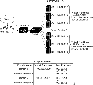
Follow this procedure to load balance across server clusters:
Step 1 Use the real command to identify the six real servers, and the is option to put the real servers in service:
ld(config)# real 192.168.1.1 is
ld(config)# real 192.168.1.2 is
ld(config)# real 192.168.1.3 is
ld(config)# real 192.168.1.4 is
ld(config)# real 192.168.1.5 is
ld(config)# real 192.168.1.6 is
Step 2 Use the virtual command to identify the two virtual servers:
ld(config)# virtual 192.168.1.100
ld(config)# virtual 192.168.1.101
Step 3 Use the bind command to direct network traffic from virtual server 192.168.1.100 to real servers 192.168.1.1, 192.168.1.2, and 192.168.1.3, and from virtual server 192.168.1.101 to real servers 192.168.1.4, 192.168.1.5, and 192.168.1.6:
ld(config)# bind 192.168.1.100 192.168.1.1 192.168.1.2  192.168.1.3
ld(config)# bind 192.168.1.101 192.168.1.4 192.168.1.5 192.168.1.6
Step 4 Use the is command to put the virtual servers in service:
ld(config)# is virtual 192.168.1.100
ld(config)# is virtual 192.168.1.101
Step 5 Use the show bind command to display the association between the virtual and real servers:
ld(config)# show bind
Virtual                      Real
192.168.1.101:0:0:tcp (IS)
                                 192.168.1.6:0:0:tcp (IS)
                                 192.168.1.5:0:0:tcp (IS)
                                 192.168.1.4:0:0:tcp (IS) 192.168.1.100:0:0:tcp (IS)
                                 192.168.1.3:0:0:tcp (IS)
                                 192.168.1.2:0:0:tcp (IS)
                                 192.168.1.1:0:0:tcp (IS)
The sticky command ensures that the same client gets the same real server for multiple connections. The sticky command allows you to get back to the same real server and retain the statefulness of the client/server connection. For example, if a client is completing an online form, the sticky command ensures that multiple connections are sent to the same server to complete the transaction. If this command is not used, each connection attempt to a virtual server is routed according to the predictor option in effect for that virtual server, without regard to prior history of the foreign host.
The sticky command does not time the length of a client connection; it times periods of inactivity. For example, if the sticky command is set to 5, and the client is active, new requests from the client are not sent to another server through load balancing, even if more than 5 minutes have elapsed. However, if 5 minutes of connection inactivity have elapsed, the requests from the client can be sent to another real server.
Follow this procedure to configure a stateful client/server connection using SSL:
Step 1 Use the virtual command to identify 192.168.1.1 as a virtual server accepting traffic on port 80 (HTTP) and port 443 (SSL):
ld(config)# virtual 192.168.1.1:80
ld(config)# virtual 192.168.1.1:443
Step 2 Use the real command to identify 192.168.1.220 and 192.168.1.221 as real servers accepting traffic on port 80 (HTTP) and port 443 (SSL):
ld(config)# real 192.168.1.220:80 is
ld(config)# real 192.168.1.221:80 is
ld(config)# real 192.168.1.220:443 is
ld(config)# real 192.168.1.221:443 is
Step 3 Use the bind command to bind the virtual servers accepting traffic on port 80 to the real servers accepting traffic on port 80:
ld(config)# bind 192.168.1.1:80 192.168.1.220:80 192.168.1.221:80
Step 4 Use the bind command to bind the virtual servers accepting traffic on port 443 to the real servers accepting traffic on port 443:
ld(config) bind 192.168.1.1:443 192.168.1.220:443 192.168.1.221:443
Step 5 Use the sticky command to ensure that requests to virtual server 192.168.1.1:443 are sent to the same real server until 10 minutes of inactivity elapse:
ld(config)# sticky 192.168.1.1:443:0:tcp 10 ssl
Step 6 Use the is command to put the virtual servers in service:
ld(config)# is virtual 192.168.1.1:80:0:tcp
ld(config)# is virtual 192.168.1.1:443:0:tcp
Step 7 Use the show bind command to display server bind associations:
ld(config)# show bind
Virtual                      Real
192.168.1.1:443:0:tcp (IS)
                             192.168.1.221:443:tcp (IS)
                             192.168.1.220:443:tcp (IS)
192.168.1.1:80:0:tcp (IS)
                             192.168.1.221:80:tcp (IS)
                             192.168.1.220:80:tcp (IS)
Step 8 Use the show sticky command to display the sticky command setting:
ld(config)# show sticky
Machine                     Sticky
   192.168.1.1:443:0:tcp    10      ssl
   192.168.1.1:80:0:tcp 0    0      ssl
Step 9 Use the show configuration command to view the entire configuration:
ld(config)# show configuration
: Saved
: LocalDirector 420 Version 3.1.0.106
syslog output 20.3
no syslog console
enable password dfeaf10390e560aea745ccba53e044 encrypted
hostname localdirector
no shutdown ethernet 0
no shutdown ethernet 1
shutdown ethernet 2
shutdown ethernet 3
interface ethernet 0 100basetx
interface ethernet 1 100basetx
interface ethernet 2 100basetx
interface ethernet 3 100basetx
mtu 0 1500
mtu 1 1500
mtu 2 1500
mtu 3 1500
multiring all
no secure  0
no secure  1
no secure  2
no secure  3
ping-allow 0
ping-allow 1
ping-allow 2
ping-allow 3
no rip passive
failover ip address 0.0.0.0
no failover
password cisco
no snmp-server contact
no snmp-server location
casa service-manager port 1638
virtual 192.168.1.1:443:0:tcp is
virtual 192.168.1.1:80:0:tcp is
real 192.168.1.221:443:0:tcp is
real 192.168.1.220:443:0:tcp is
real 192.168.1.221:80:0:tcp is
real 192.168.1.220:80:0:tcp is
bind 192.168.1.1:443:0:tcp 192.168.1.220:443:0:tcp
bind 192.168.1.1:80:0:tcp 192.168.1.221:80:0:tcp
bind 192.168.1.1:80:0:tcp 192.168.1.220:80:0:tcp
sticky 192.168.1.1:443:0:tcp 10 ssl
: end
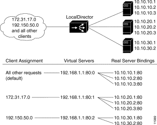
Use the assign command to associate real servers to the bind-ids of virtual servers and direct client requests to a specific instance of a virtual server, as shown in Figure 4-8. Depending on the bindings of virtual servers to real servers, different real machines are used for different clients.
In this example, clients from 172.31.17.0 are directed through the virtual server with a
bind-id of 1 to the real servers with IP addresses 10.10.20.1, 10.10.20.2, and 10.10.20.3. Client requests from 192.150.50.0 go through the virtual server with a bind-id of 2 to real servers with IP addresses 10.10.30.1 and 10.10.30.2. Requests from any other source IP address go to the virtual server with the default bind-id of 0, and that virtual server is bound to real servers 10.10.10.1, 10.10.10.2, and 10.10.10.3.
Follow this procedure to configure client-assigned load balancing:
Step 1 Use the virtual command to create a virtual server that accepts client traffic not assigned to a specific bind-id. Use the real command to create three real servers. Use the bind command to bind three real servers to the virtual server:
ld(config)# virtual 192.168.1.1:80:tcp
ld(config)# real 10.10.10.1:80:0:tcp
ld(config)# real 10.10.10.2:80:0:tcp
ld(config)# real 10.10.10.3:80:0:tcp
ld(config)# bind 192.168.1.1:80:0:tcp 10.10.10.1:80:0:tcp
ld(config)# bind 192.168.1.1:80:0:tcp 10.10.10.2:80:0:tcp
ld(config)# bind 192.168.1.1:80:0:tcp 10.10.10.3:80:0:tcp
Step 2 Use the virtual command to create a virtual server with a bind-id of :1. Use the real command to create three real servers. Use the bind command to bind three real servers to the virtual server:
ld(config)# virtual 192.168.1.1:80:1:tcp
ld(config)# real 10.10.20.1:80:0:tcp
ld(config)# real 10.10.20.2:80:0:tcp
ld(config)# real 10.10.20.3:80:0:tcp
ld(config)# bind 192.168.1.1:80:1:tcp 10.10.20.1:80:0:tcp
ld(config)# bind 192.168.1.1:80:1:tcp 10.10.20.2:80:0:tcp
ld(config)# bind 192.168.1.1:80:1:tcp 10.10.20.3:80:0:tcp
Step 3 Use the virtual command to create a virtual server with a bind-id of :2. Use the real command to create three real servers. Use the bind command to bind three real servers to the virtual server:
ld(config)# virtual 192.168.1.1:80:2:tcp
ld(config)# real 10.10.30.1:80:0:tcp
ld(config)# real 10.10.30.2:80:0:tcp
ld(config)# real 10.10.30.3:80:0:tcp
ld(config)# bind 192.168.1.1:80:2:tcp 10.10.30.1:80:0:tcp ld(config)# bind 192.168.1.1:80:2:tcp 10.10.30.2:80:0:tcp
ld(config)# bind 192.168.1.1:80:2:tcp 10.10.30.3:80:0:tcp
Step 4 Use the assign command to assign clients from network 172.31.17.0 to the virtual server with a bind-id of :1, and assign clients from 192.150.50.0 to the virtual server with a bind-id of :2. Using a zero in the fourth octet of the subnet mask includes the entire range for the client IP address:
ld(config)# assign 192.168.1.1:80:1:tcp 172.31.17.0 255.255.255.0
ld(config)# assign 192.168.1.1:80:2:tcp 192.150.50.0 255.255.255.0
Step 5 Use the is command to put the virtual servers and real servers in service.
ld(config)# is virtual 192.168.1.1:80:2:tcp
ld(config)# is virtual 192.168.1.1:80:0:tcp
ld(config)# is virtual 192.168.1.1:80:1:tcp
ld(config)# is real 10.10.30.2:80:0:tcp
ld(config)# is real 10.10.30.1:80:0:tcp
ld(config)# is real 10.10.20.3:80:0:tcp
ld(config)# is real 10.10.20.2:80:0:tcp
ld(config)# is real 10.10.10.3:80:0:tcp
ld(config)# is real 10.10.10.2:80:0:tcp
ld(config)# is real 10.10.10.1:80:0:tcp
ld(config)# is real 10.10.20.1:80:0:tcp
Step 6 Use the show configuration command to view the entire configuration:
ld(config)# show configuration
: Saved
: LocalDirector 420 Version 3.1.0.106
syslog output 20.3
no syslog console
enable password dfeaf10390e560aea745ccba53e044 encrypted
hostname localdirector
no shutdown ethernet 0
no shutdown ethernet 1
shutdown ethernet 2
shutdown ethernet 3
interface ethernet 0 100basetx
interface ethernet 1 100basetx
interface ethernet 2 100basetx
interface ethernet 3 100basetx
mtu 0 1500
mtu 1 1500
mtu 2 1500
mtu 3 1500
multiring all
no secure  0
no secure  1
no secure  2
no secure  3
ping-allow 0
ping-allow 1
ping-allow 2
ping-allow 3
ip address 172.20.30.81 255.255.255.0
no rip passive
failover ip address 0.0.0.0
no failover
password cisco
no snmp-server contact
no snmp-server location
casa service-manager port 1638
virtual 192.168.1.1:80:2:tcp is
virtual 192.168.1.1:80:0:tcp is
virtual 192.168.1.1:80:1:tcp is
real 10.10.30.2:80:0:tcp is
real 10.10.30.1:80:0:tcp is
real 10.10.20.3:80:0:tcp is
real 10.10.20.2:80:0:tcp is
real 10.10.10.3:80:0:tcp is
real 10.10.10.2:80:0:tcp is
real 10.10.10.1:80:0:tcp is
real 10.10.20.1:80:0:tcp is
bind 192.168.1.1:80:2:tcp 10.10.30.2:80:0:tcp
bind 192.168.1.1:80:2:tcp 10.10.30.1:80:0:tcp
bind 192.168.1.1:80:0:tcp 10.10.10.3:80:0:tcp
bind 192.168.1.1:80:0:tcp 10.10.10.2:80:0:tcp
bind 192.168.1.1:80:0:tcp 10.10.10.1:80:0:tcp
bind 192.168.1.1:80:1:tcp 10.10.20.3:80:0:tcp
bind 192.168.1.1:80:1:tcp 10.10.20.2:80:0:tcp
bind 192.168.1.1:80:1:tcp 10.10.20.1:80:0:tcp
assign 192.168.1.1:80:2:tcp 192.150.50.0 255.255.255.0
assign 192.168.1.1:80:1:tcp 192.31.17.0 255.255.255.0
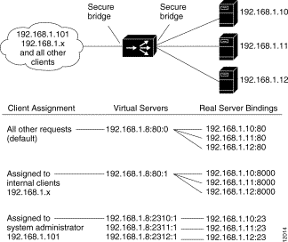
The example shown in Figure 4-9 uses LocalDirector security features of SecureAccess, SecureBind, and SecureBridge to secure a network both internally and externally.
In this example, the company has a Class C network with an IP address of 192.168.1.0. The virtual address in DNS is 192.168.1.8 for www.domain.com. Requests from internal clients are directed to different real servers. The IP address of the system administrator is 192.168.1.101.
Follow this procedure to configure secure services:
Step 1 Use the secure command to turn on the SecureBridge feature:
ld(config)# secure 0
ld(config)# secure 1
Step 2 Use the virtual command to create a virtual address for Internet Web access:
ld(config)# virtual 192.168.1.8:80:0:tcp is
Step 3 Use the virtual command to create a virtual address for internal Web access:
ld(config)# virtual 192.168.1.8:80:1:tcp is
Step 4 Use the virtual command to create virtual addresses for the system administrator to access the real servers through a Telnet session:
ld(config)# virtual 192.168.1.8:2310:1 is
ld(config)# virtual 192.168.1.8:2311:1 is
ld(config)# virtual 192.168.1.8:2312:1 is
Step 5 Use the real command to define the three real servers that are serving the Internet Web:
ld(config)# real 192.168.1.10:80:0:tcp is
ld(config)# real 192.168.1.11:80:0:tcp is
ld(config)# real 192.168.1.12:80:0:tcp is
Step 6 Use the real command to define the three real servers that are serving the internal Web:
ld(config)# real 192.168.1.10:8000:0:tcp is
ld(config)# real 192.168.1.11:8000:0:tcp is
ld(config)# real 192.168.1.12:8000:0:tcp is
Step 7 Use the real command to define the three real servers that provide Telnet access for the system administrator:
ld(config)# real 192.168.1.10:23 is
ld(config)# real 192.168.1.11:23 is
ld(config)# real 192.168.1.12:23 is
Step 8 Use the bind command to bind the system administrator virtual addresses to the real servers:
ld(config)# bind 192.168.1.8:2310:1 192.168.1.10:23
ld(config)# bind 192.168.1.8:2311:1 192.168.1.11:23
ld(config)# bind 192.168.1.8:2312:1 192.168.1.12:23
Step 9 Use the bind command to bind the Internet Web server virtual address to the real servers:
ld(config)# bind 192.168.1.8:80:0:tcp 192.168.1.10:80:tcp
ld(config)# bind 192.168.1.8:80:0:tcp 192.168.1.11:80:tcp
ld(config)# bind 192.168.1.8:80:0:tcp 192.168.1.12:80:tcp
Step 10 Use the bind command to bind the internal Web server virtual address to the real servers:
ld(config)# bind 192.168.1.1:80:1:tcp 192.168.1.10:8000:0:tcp
ld(config)# bind 192.168.1.1:80:1:tcp 192.168.1.11:8000:0:tcp
ld(config)# bind 192.168.1.1:80:1:tcp 192.168.1.12:8000:0:tcp
Step 11 Use the assign command to give only the system administrator access to the Telnet virtual addresses. The subnet mask of 255.255.255.255 restricts access to the individual IP address.
ld(config)# assign 192.168.1.8:2310:1 192.168.1.101 255.255.255.255
ld(config)# assign 192.168.1.8:2311:1 192.168.1.101 255.255.255.255
ld(config)# assign 192.168.1.8:2312:1 192.168.1.101 255.255.255.255
Step 12 Use the assign command to give only internal clients access to the virtual addresses for the internal Web. The subnet mask of 255.255.255.0 restricts access to the network IP address:
ld(config)# assign 192.168.1.8:80:1:tcp 192.168.1.0 255.255.255.0
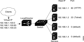
IP services can be directed to specific servers. Figure 4-10 shows how to send HTTP traffic to server A, send Telnet traffic to server B, and direct all other traffic to servers C and D. Three virtual servers have IP address 192.168.1.100; one accepts only HTTP traffic (port 80), one accepts Telnet traffic (port 23), and the other accepts all other connections (default).
Names can also be used to refer to the real and virtual servers in this example.
Follow this procedure to configure port-bound servers:
Step 1 Use the real command to identify a real server accepting connections on port 80, a real server accepting connections on port 23, and two real servers accepting default traffic:
ld(config)# real 192.168.1.1:80 is
ld(config)# real 192.168.1.2:23 is
ld(config)# real 192.168.1.3 is
ld(config)# real 192.168.1.4 is
Step 2 Use the virtual command to identify three virtual servers for IP address 192.168.1.100: one accepting connections on port 80, one accepting connections on port 23, and one accepting default traffic:
ld(config)# virtual 192.168.1.100:80 is
ld(config)# virtual 192.168.1.100:23 is
ld(config)# virtual 192.168.1.100 is
Step 3 Use the bind command to direct HTTP traffic for virtual server 192.168.1.100, port 80 to real server 192.168.1.1, port 80:
ld(config)# bind 192.168.1.100:80 192.168.1.1:80
Step 4 Use the bind command to direct Telnet traffic for virtual server 192.168.1.100, port 23 to real server 192.168.1.2, port 23:
ld(config)# bind 192.168.1.100:23 192.168.1.2:23
Step 5 Use the bind command to direct all other connections for virtual server 192.168.1.100 to real servers 192.168.1.3 and 192.168.1.4:
ld(config)# bind 192.168.1.100 192.168.1.3 192.168.1.4
Step 6 Use the show bind command to display the association between the virtual and real servers:
ld(config)# show bind
  Virtual                      Real
  192.168.1.100:0:0(IS)
                               192.168.1.4:0(IS)
                               192.168.1.3:0(IS)
  192.168.1.100:23:0(IS)
                               192.168.1.2:23(IS)
  192.168.1.100:80:0(IS)
                               192.168.1.1:80(IS)
The maxconns command allows you to specify the maximum number of connections that each real server can have at one time. A server administrator can set the maximum connections to a level that avoids exceeding the capacity threshold of the server. Often, server administrators have a good idea of the load that a server can bear, and the maxconns command can be used to prevent a server from failing because of capacity overload. Clients requesting connections to a server farm with no available connections receive a timeout message.
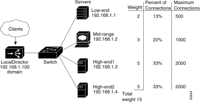
A higher percentage of connections can be directed to servers that offer increased performance by selecting the weighted option of the predictor command and setting values with the weight command.
Figure 4-11 shows four servers with varying performance indices, maximum connections settings, and weight values. In this example, a weight of 2 is assigned to the low-end server, sending 13 percent of the connections to that server. This particular server cannot accept more than 500 simultaneous connections, so maxconns is set to 500. The same reasoning applies to the midrange server and the two high-end servers.
Follow this procedure to configure maximum connections and weighted performance:
Step 1 Use the virtual command to identify 192.168.1.100 as a virtual server. Use the is option to put the server in service:
ld(config)# virtual 192.168.1.100 is
Step 2 Use the name command to associate a name with the virtual server:
ld(config)# name 192.168.1.100 domain
Step 3 Use the real command to identify four real servers. Use the is option to put the servers in service:
ld(config)# real 192.168.1.1 is
ld(config)# real 192.168.1.2 is
ld(config)# real 192.168.1.3 is
ld(config)# real 192.168.1.4 is
Step 4 Use the name command to associate names with the real servers:
ld(config)# name 192.168.1.1 low-end
ld(config)# name 192.168.1.2 mid-range
ld(config)# name 192.168.1.3 high-end1
ld(config)# name 192.168.1.4 high-end2
Step 5 Use the bind command to direct traffic for virtual server domain to real servers low-end, mid-range, high-end1, and high-end2:
ld(config)# bind domain low-end mid-range high-end1 high-end2
Step 6 Use the predictor command to set load balancing with the weighted option:
ld(config)# predictor domain weighted
Step 7 Use the weight command to assign weight values to each of the real servers:
ld(config)# weight low-end 2
ld(config)# weight mid-range 3
ld(config)# weight high-end1 5
ld(config)# weight high-end2 5
Step 8 Use the maxconns command to limit the number of connections that each real server can accept:
ld(config)# maxconns low-end 500
ld(config)# maxconns mid-range 1000
ld(config)# maxconns high-end1 2000
ld(config)# maxconns high-end2 2000
Step 9 Use the show bind command to display the association between the virtual and real servers:
ld(config)# show bind
  Virtual                      Real
    domain:0:0(IS)
                               high-end2:0(IS)
                               high-end1:0(IS)
                               mid-range:0(IS)
                               low-end:0(IS)
Step 10 Use the show weight command to display the weight values assigned to the real servers:
ld(config)# show weight
             Machine Weight
         high-end1:0     5
         mid-range:0     3
           low-end:0     2
         high-end2:0     5
For real servers, a backup is used if the real server has failed or is out of service. For a virtual server, a backup is used if all real servers (and their backups) bound to the virtual server have failed or are out of service. If the virtual server itself is out of service, a TCP RST is sent to the client requesting the connection.
When the server being backed up returns to service, connections are no longer directed to the backup server and they are sent according to the LocalDirector configuration.
You can back up real servers with virtual addresses, and you can back up virtual servers with a real server. You can use a backup server when the real or virtual server is not in service (for example, it has failed or is out of service).
The following example shows a virtual server backing up another virtual server. If real servers 1.1.1.2 and 1.1.1.3 fail (thus failing virtual server 10.10.10.10), the real servers bound to virtual server 10.10.10.20 are used instead.
ld(config)# virtual 10.10.10.10
ld(config)# real 1.1.1.2
ld(config)# real 1.1.1.3
ld(config)# bind 10.10.10.10 1.1.1.2 1.1.1.3
ld(config)# virtual 10.10.10.20
ld(config)# real 1.1.1.4
ld(config)# real 1.1.1.5
ld(config)# real 1.1.1.6
ld(config)# bind 10.10.10.20 1.1.1.4 1.1.1.5 1.1.1.6
ld(config)# backup 10.10.10.10 10.10.10.20
In the following example, real server 1.1.1.4 is backing up the two real servers bound to virtual server 10.10.10.10:
ld(config)# virtual 10.10.10.10
ld(config)# real 1.1.1.2
ld(config)# real 1.1.1.3
ld(config)# bind 10.10.10.10 1.1.1.2 1.1.1.3
ld(config)# real 1.1.1.4
ld(config)# backup 10.10.10.10 1.1.1.4
The same result can be achieved with the following configuration, where real server 1.1.1.4 backs up the two real servers directly, instead of backing up the virtual server:
ld(config)# virtual 10.10.10.10
ld(config)# real 1.1.1.2
ld(config)# real 1.1.1.3
ld(config)# bind 10.10.10.10 1.1.1.2 1.1.1.3
ld(config)# real 1.1.1.4
ld(config)# backup 1.1.1.2 1.1.1.4
ld(config)# backup 1.1.1.3 1.1.1.4
LocalDirector tracks connections and can detect when clients are requesting data and the server is not responding with data. If the DataIn Conns value of a server exceeds the defined threshold and all other real servers bound to the virtual server are at less than 80 percent of their DataIn capacity, the server is failed. Display the DataIn Conns value with the show real command.
This section describes how to set up UDP traffic on the virtual servers and real servers, and a mix of TCP and UDP traffic on the virtual servers and real servers.
Configuration for UDP is similar to TCP, except the udp protocol option is used instead of the tcp option in the virtual_id and real_id server parameters. Additionally, because UDP is a connectionless protocol, the connection is kept alive through use of a timer.
The connection duration timer starts on the first packet of the flow that is received on the virtual server. Set the timer with the timeout command, as shown in the following example. Connections remain valid until the timer times out because of inactivity on the connection flow.
Follow this procedure to set up a UDP configuration for a virtual server and a real server:
Step 1 Use the virtual command to identify 192.10.10.101 as a virtual server running UDP through port 300. Use the is option to put the server in service.
ld(config)# virtual 192.10.10.101:300:0:udp is
Step 2 Use the timeout command to set the connection duration period on the virtual server to 11 minutes.
ld(config)# timeout 192.10.10.101:300:0:udp 11
Step 3 Use the real command to identify 192.10.10.1:300:0 as a real server running UDP through port 300. Use the is option to put the server in service.
ld(config)# real 192.10.10.1:300:0:udp is
Step 4 Use the bind command to associate the virtual server to the real server:
ld(config)# bind 192.10.10.101:300:0:udp 192.10.10.1:300:0:udp
When an application can use a known connection port, the buddy command can be used to group the connections, ensuring that activity on one stream updates timers on all streams.
Follow this procedure to set up a buddy group that contains TCP and UDP virtual servers representing TCP and UDP real servers:
Step 1 Use the virtual command to identify 10.0.0.100 as a virtual server running TCP and UDP. Use the is option to put the server in service.
ld(config)# virtual 10.0.0.100:0:0:tcp is
ld(config)# virtual 10.0.0.100:0:0:udp is
Step 2 Use the buddy command to create the buddy group tcp-udp and add the TCP and UDP virtual servers to it:
ld(config)# buddy tcp-udp 10.0.0.100:0:0:tcp
ld(config)# buddy tcp-udp 10.0.0.100:0:0:udp
Step 3 Use the real command to identify three real servers running both TCP and UDP. Use the is option to put the servers in service.
ld(config)# real 10.0.0.1:0:0:tcp is
ld(config)# real 10.0.0.1:0:0:udp is
ld(config)# real 10.0.0.2:0:0:tcp is
ld(config)# real 10.0.0.2:0:0:udp is
ld(config)# real 10.0.0.3:0:0:tcp is
ld(config)# real 10.0.0.3:0:0:udp is
Step 4 Use the bind command to associate the virtual servers to the real servers. Notice the TCP virtual servers are bound to the TCP real servers.
ld(config)# bind 10.0.0.100:0:0:tcp 10.0.0.3:0:0:tcp
ld(config)# bind 10.0.0.100:0:0:tcp 10.0.0.2:0:0:tcp
ld(config)# bind 10.0.0.100:0:0:tcp 10.0.0.1:0:0:tcp
ld(config)# bind 10.0.0.100:0:0:udp 10.0.0.3:0:0:udp
ld(config)# bind 10.0.0.100:0:0:udp 10.0.0.2:0:0:udp
ld(config)# bind 10.0.0.100:0:0:udp 10.0.0.1:0:0:udp
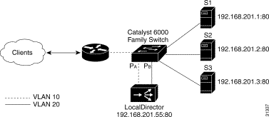
Accelerated server load balancing (ASLB) requires two Ethernet links between LocalDirector and the Catalyst 6000 family switch. One link must be connected to the VLAN that the router is on (VLAN 10 in Figure 4-12). The other link must be connected to the VLAN that the real servers are on (VLAN 20 in Figure 4-12).
Follow this procedure to set up ASLB according to the information in Figure 4-12:
Step 1 Use the virtual command to identify 192.233.201.55:80 as a virtual server:
ld(config)# virtual 192.233.201.55:80
Step 2 Use the real command to identify the three servers:
ld(config)# real 192.255.201.1:80
ld(config)# real 192.255.201.2:80
ld(config)# real 192.255.201.3:80
Step 3 Use the bind command to associate the virtual server to the real servers:
ld(config)# bind 192.255.201.55:80 192.255.201.1:80
ld(config)# bind 192.255.201.55:80 192.255.201.2:80
ld(config)# bind 192.255.201.55:80 192.255.201.3:80
Step 4 Use the predictor command to set load balancing with the roundrobin option:
ld(config)# predictor 192.255.201.55:80 roundrobin
Step 5 Use the redirection command to enable ASLB for the virtual server with the dispatch assisted option:
ld(config)# redirection 192.255.201.55.80 dispatch assisted
 Sample ASLB Configuration
When an inbound connection synchronization (TCP SYN) packet arrives with a destination MAC address of LocalDirector virtual server in the Layer 3 header, the switch forwards the packet to LocalDirector at port PA. LocalDirector makes the load balance decision, changes the destination MAC address to that of the real server, and forwards the packet to the switch at port PB. The switch creates an inbound ASLB Multilayer Switching (MLS) entry in the Layer 3 forwarding tables as it forwards the packet to the real server. All subsequent packets that match the inbound ASLB MLS entry are Layer 3-switched (accelerated) to the real server, unless the packet is fragmented or contains a connection finish (TCP FIN) or connection reset (TCP RST).
When the outbound SYN packet from the real server arrives, the switch forwards the packet to LocalDirector at port PB. The Local Director changes the source MAC address to that of the LocalDirector virtual server and forwards the packet to the switch at port PA.The switch creates an outbound ASLB MLS entry in the Layer 3 forwarding table as it forwards the packet to the router. All subsequent packets that match the outbound ASLB MLS entry are switched directly to the router, unless the packet is fragmented or contains a FIN or RST.
Packets containing a FIN or RST travel the same path as a SYN packet. The switch purges the inbound ASLB MLS entry when it forwards the FIN or RST packet to LocalDirector. The switch purges the outbound ASLB MLS entry as it forwards the FIN or RST packet to LocalDirector.
![]()
![]()
![]()
![]()
![]()
![]()
![]()
![]()
Posted: Tue Feb 22 15:33:55 PST 2000
Copyright 1989 - 2000©Cisco Systems Inc.