|
|

Table Of Contents
Stateful Failover Implementation
Fault-Tolerant Failover Implementation
LocalDirector Failover
This chapter describes LocalDirector failover and contains the following sections:
•
Show Failover Command Output
If you set up two LocalDirectors with the same configuration (same model, interface connections, and software release), they can provide backup capabilities for each other, should one fail. This redundant configuration, in conjunction with the hardware and software to set up, monitor, and provide the switch from the failed unit to the backup unit, is called LocalDirector failover.
In a failover configuration, one LocalDirector unit is considered the "primary" unit, while the other is considered the "secondary" unit. The primary unit is also the active unit by default, and it performs normal network functions. The backup unit (standby) only monitors the communication between the failover units, ready to take control should the active unit fail. When a failure occurs, the units toggle operations as one picks up for the other and exchange Media Access Control (MAC) addresses, but they do not redesignate themselves from "primary" to "secondary," or vice versa.
Note
The active unit uses the system IP address and the MAC address of the primary unit. The standby unit uses the failover IP address and the secondary MAC address. Because the active unit uses the same IP and MAC addresses (regardless of which physical unit it is), no Address Resolution Protocol (ARP) entries need to change or time out anywhere on the network.
Failover monitors the failover communications, power status of the other unit, interface line status, and hello packets that are received on each interface. A failure of any of these parameters on the active unit causes the standby unit to take active control. When a failure or switch occurs, SYSLOG messages are generated indicating the cause of the failure.
To take a unit out of the "failed" state, cycle the power or use the failover reset command. The failover reset command also clears failover timers and counters for the LocalDirector unit. When a failed primary unit is brought back online, it does not automatically resume as the active unit because it could immediately enter a failed state again. However, if a failure is due to a lost signal on a network interface card, failover "autorecovers" when the network is available again.
Use the failover active command to initiate a failover switch from the standby unit, or the no failover active command from the active unit to initiate a failover switch. You can use this feature to force an active unit offline for maintenance.
Note
By default, the standby unit does not keep state information on each connection; all active connections are dropped and must be reestablished by the clients. However, if you configure stateful failover on LocalDirectors, the standby LocalDirector not only has copies of the active LocalDirector configuration, but also has copies of the tables that show the active connections and their state. If the active unit fails, these connections are still valid, and users continue an active session with the server. Use the replicate command to configure stateful failover on a per-virtual basis.
The configuration of the primary unit is copied to the secondary unit in the following conditions:
•
•
•
Failover Setup
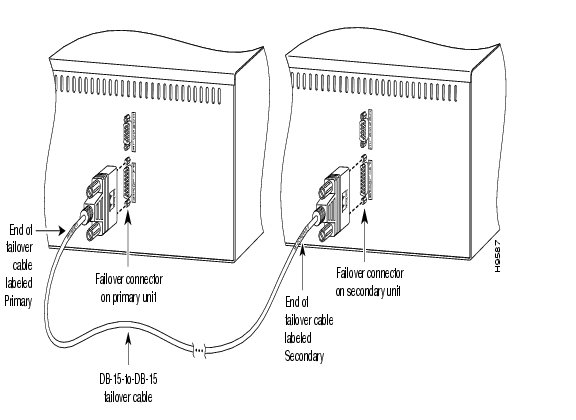
Follow this procedure to set up a failover configuration. shows the physical connections for the primary and secondary units.
Figure 5-1 Basic Failover Implementation on a LocalDirector 416
Step 1
Step 2
Figure 5-2 Failover Cable
Note
Step 3
•
•
•
•
Step 4
Step 5
To take advantage of multiple IP addresses or dispatched mode, or allow the failover unit to be on a different network than the real servers, use the failover alias ip address command to set up an alias on the standby failover unit. A maximum of 256 aliases are allowed.
Step 6
Step 7
Note
Step 8
Step 9
Step 10
•
•
Failover Command Summary
lists the commands that are used for failover configurations. For complete descriptions of these commands, refer to Chapter 6, "Command Reference."
Failover Examples
This section describes the following examples of failover configurations:
•
•
•
Basic Failover Implementation
showed a basic failover implementation. Note that the third interface on LocalDirector 416 is not being used. In this example, the shutdown command must be used to disable the interface; otherwise the unit is seen as failed.
Note
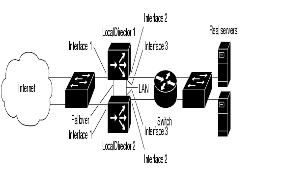
Stateful Failover Implementation
shows stateful failover with a dedicated interface, provided by the crossover cable.
Use the replicate interface command to identify the dedicated interface, as follows:
ld(config)# replicate interface 3The ports on the 4-port interface are numbered 0 to 3. This command dedicates the bottom port on the card to stateful failover.
Note
Figure 5-3 Stateful Failover on a LocalDirector 430 with a Dedicated Interface
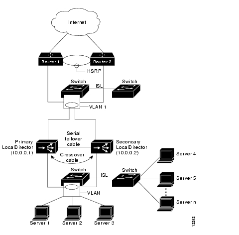
Fault-Tolerant Failover Implementation
Many sites employ LocalDirectors in situations of heavy traffic loads, where redundant switches are used to route incoming traffic to multiple locations, including LocalDirectors. shows a LocalDirector configuration that is fault tolerant.
The configuration in produces the following results, given any component failure:
•
•
•
Note that in the configuration, failure of a server-side switch removes access to the servers attached to it. This situation can be minimized by utilizing servers with dual LAN ports, such as exist on some LAN cards designed for redundant links.
Figure 5-4 Fault-Tolerant Failover Configuration
Redundant Power Planning
In planning for redundant Web sites, it is wise to plan for power failures, so that equipment affected is backed up by other equipment that is not on the same power circuit.
It also makes sense to not provide power in such a way that multiple failovers occur at the same time; for example, having a gateway router and a switch served by the same power circuit or supply. This situation would mean that a switch and router would both try to converge their routes at the same time, which would cause problems in a heavily loaded network.
Failover Interface Tests
If there is a loss of network communication over an interface, failover begins a series of tests to determine which unit failed. These tests begin when hello messages are not heard for six consecutive 5-second intervals. Hello messages are sent over both network interfaces and the serial cable every 5 seconds.
The tests generate network traffic to determine which (if either) unit is failed. At the start of each test, each unit clears its received packet count for its interfaces. At the conclusion of each test, each unit checks if it has received any traffic. If it has, the interface is considered operational. If one unit receives traffic for a test and the other unit does not, the unit that received no traffic is considered failed. If neither unit has received traffic, they go to the next test.
Note
The following lists the failover interface tests:
•
This is a test of the network interface card. If an interface card is not plugged into an operational network, it is considered failed (for example, the hub or switch is failed, has a failed port, or a cable is unplugged).
•
This is a received network activity test. The unit counts all received packets for up to
5 seconds. If any packets are received at any time during this interval, the interface is considered operational and testing stops. If neither unit receives traffic, the ARP test begins.•
The ARP test consists of reading the ARP cache for the ten most recently acquired ARP entries. One at a time, the unit sends ARP requests to these servers attempting to stimulate network traffic. After each request, each unit counts all received traffic for up to 5 seconds. If traffic is received, the interface is considered operational. If no traffic is received by either unit, an ARP request is sent to the next server. After tying the ten entries, if no traffic has been received, the ping broadcast test begins.
•
The broadcast ping test consists of sending out a broadcast ping request. Each unit then counts all received packets for up to 5 seconds. If any packets are received at any time during this interval, the interface is considered operational and testing stops. If no traffic is received, the testing starts over again with the ARP test.
Failover SYSLOG Messages
Failover messages always have a SYSLOG priority level of 2, which indicates a critical condition. All failover SYSLOG messages are also sent as Simple Network Management Protocol (SNMP) SYSLOG traps.
To receive SNMP SYSLOG traps (SNMP failover traps), the SNMP agent must be configured to send SNMP traps to SNMP management stations, define a SYSLOG host, and also compile the Cisco SYSLOG MIB into your SNMP management station. See the snmp-server and syslog command descriptions in Chapter 6, " Command Reference," for more information.
The SYSLOG messages sent to record failover events are listed in the " SYSLOG and SNMP Messages" section of Appendix A, " ."
Show Failover Command Output
The following is the normal output of the show failover command. Note that the IP address that each unit is using is displayed.
ld-prim(config)# show failoverFailover OnCable status: NormalThis host: Primary - ActiveActive time: 6885 (sec)Interface 0 (192.168.89.1): NormalInterface 1 (192.168.89.1): NormalOther host: Secondary - StandbyActive time: 0 (sec)Interface 0 (192.168.89.2): NormalInterface 1 (192.168.89.2): NormalFailover does not start monitoring the network interfaces until it has heard the sixth hello packet from the other unit on that interface, which should happen within 30 to 60 seconds.
If the unit is attached to a switch running spanning tree, the start of failover monitoring takes twice the forward delay time configured in the switch (typically 15 seconds) plus
30 seconds. This delay is because at bootup (and immediately following a failover event) the network switch detects a temporary bridge loop. When this bridge loop is detected, the switch stops forwarding packets for the duration of the forwarding delay time. It then enters "listen" mode for an additional forward delay time while the switch is listening for bridge loops but still not forwarding traffic (including failover hello packets).After twice the forward delay time (30 seconds), traffic should resume. LocalDirector remains in "waiting" mode until it hears six hello packets (1 every 5 seconds for a total of 30 seconds). During this time, LocalDirector is passing traffic and does not fail the unit based on not hearing the hello packets. All other failover monitoring continues (power, interface, and failover cable hello).
Note
The following example shows the output if failover has not started monitoring the network interfaces:
ld-prim(config)# show failoverFailover OnCable status: NormalThis host: Primary - ActiveActive time: 6930 (sec)Interface 0 (192.168.89.1): Normal (Waiting)Interface 1 (192.168.89.1): Normal (Waiting)Other host: Secondary - StandbyActive time: 15 (sec)Interface 0 (192.168.89.2): Normal (Waiting)Interface 1 (192.168.89.2): Normal (Waiting)
Note
The following example shows that a failure has been detected. Note that interface 1 on the primary unit is the source of the failure. The units are back in waiting mode because of the failure. The failed unit has removed itself from the network (interfaces are down) and it is no longer sending hello packets on the network. The active unit remains in the waiting state until the failed unit is replaced and failover communications start again.
ld-prim(config)# show failoverFailover OnCable status: NormalThis host: Primary - Standby (Failed)Active time: 7140 (sec)Interface 0 (192.168.89.2): Normal (Waiting)Interface 1 (192.168.89.2): Failed (Waiting)Other host: Secondary - ActiveActive time: 30 (sec)Interface 0 (192.168.89.1): Normal (Waiting)Interface 1 (192.168.89.1): Normal (Waiting)Frequently Asked Questions
This section contains some frequently asked questions about the failover feature.
•
No, failover does not work without the cable. If you run without the failover cable, you are essentially running two separate LocalDirectors, which results in a bridge loop and floods the network. The failover cable is an essential part of failover.
•
When a unit boots up, it defaults to Failover Off and Secondary unless the failover cable is present or failover has been saved in the configuration. The configuration from the active unit is also copied to the standby unit. If the cable is not present, the unit automatically becomes the active unit. If the cable is present, the unit that has the primary end of the failover cable plugged into it becomes the primary unit by default, unless the secondary unit is already active.
•
No, the cable cannot be extended using modems or other EIA/TIA-232 line extenders. Part of what the failover cable does is indicate the presence and power status of the other unit. When you place line extenders in this path, you are relaying the status of the line extender rather than the status of the other LocalDirector unit.
•
A switch can be initiated by either unit. When a switch takes place, each unit changes state. The newly active unit assumes the IP address and MAC address of the previously active unit and begins accepting traffic for it. The new standby unit assumes the IP address and MAC address of the unit that was previously the standby unit.
•
Use the replicate command to maintain connection state on a per-virtual basis. If the replicate command is not used, active connections are dropped when a failover switch occurs, and clients must reestablish the connections through the newly active unit. It is best to maintain state on connections with a longer connection time. Although it is possible to maintain state on connections that are short-lived such as HTTP, it is not recommended.
•
The configuration is automatically replicated and can be forced with the write standby command.
•
When the primary active LocalDirector experiences a power failure, the standby LocalDirector comes up in active mode. If the primary unit is powered up again, it becomes the standby unit.
•
When the primary active LocalDirector is failed by disconnecting the network interface (cable pull), the standby LocalDirector comes up in active mode as it should. When the interface is plugged back in, the unit automatically recovers; however, it does not take over as the active unit. It becomes the standby unit.
•
Yes, if you are running LocalDirector Version 1.6.3 or greater on both units.
•
Fault detection is based on the following:
— Failover hello packets are received on each interface. If hello packets are not heard for six consecutive 5-second intervals, the interface is tested to determine which unit is at fault.— Cable errors. The cable is wired so that each unit can distinguish between a power failure in the other unit and an unplugged cable. If the standby unit detects that the active unit is powered down (or resets) it takes active control. If the cable is unplugged, a SYSLOG message is generated but no switching occurs. An exception is at boot-up, at which point an unplugged cable forces the unit active. If both units are powered up without the failover cable installed, they both become active, creating a duplicate IP address conflict on your network. The failover cable must be installed for failover to work correctly.— Failover communication. The two units share information every 5 seconds. If the standby unit does not hear from the active unit in six communication attempts (and the cable status is OK), the standby unit takes over as active.•
— Network errors are detected within 30 seconds.— Power failure (and cable failure) is detected within 5 seconds.— Failover communications errors are detected within 30 seconds.•
SYSLOG messages are generated when any errors or switches occur. Evaluate the failed unit and repair or replace it.
•
Always use the same version of software on both LocalDirector units.
Note
•
See "Software Upgrade," for failover upgrade instructions.
•
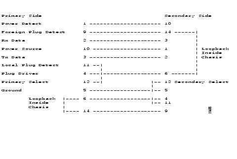
The failover cable is shown in , and the pinouts for the failover cable are shown in . The cable is 6 feet (2 meters) long, and both ends are receptacle DB-15. The EIA/TIA-232 standard specifies that cables can be up to 75 feet (22 meters) long.
Figure 5-5 Failover Cable Pinouts
![]()
![]()
![]()
![]()
![]()
![]()
![]()
![]()
Posted: Wed Nov 10 22:45:22 PST 2004
All contents are Copyright © 1992--2004 Cisco Systems, Inc. All rights reserved.
Important Notices and Privacy Statement.