|
|

This chapter describes the Cisco 6400 Service Connection Manager (SCM) deployment process in detail.
Deployment is the feature that informs the Cisco 6400 SCM of the presence of supported network elements. Perform the deployment process after starting the Cisco 6400 SCM for the first time or after installing new hardware or network elements.
The Cisco 6400 SCM objects can be deployed manually or automatically by launching a wizard-style deployment tool that enables you to automatically deploy a network modeled in Cisco EMF. The deployment wizard deploys objects in Cisco EMF in advance of actual deployment on a Cisco 6400 SCM in the field. The Cisco 6400 SCM detects the presence of previously deployed network equipment as soon as that equipment becomes operational. The Cisco 6400 SCM can auto-discover equipment as an alternative to manual deployment.
Deployment is the first stage of equipment provisioning. It is also referred to as pre-provisioning--meaning that part of the network hardware setup before the service is actually provisioned. After objects are deployed, the initial state of all objects is normal.
Pre-provisioning is the process of reserving and configuring a space in the system for network equipment, which have not yet been physically slotted into the system rack. It refers to a particular state of the device or object. When an object or device is in a pre-provisioned state, the device or object is not present, but the system has been pre-provisioned to hold an object of similar type. Thus the Node Line Cards in the Cisco 6400 SCM can exist in a state known as pre-provisioned and the Cisco 6400 SCM does not monitor their status. When the cards are placed in the physical equipment, it is possible to change the Node Line Card from the decommissioned state to the commissioned state by clicking the Commission button.
 |
Note Objects try to achieve a Commissioned state after subchassis discovery. After manual deployment the initial state of all objects is Decommissioned, unless you selected the Cisco 6400 SCM Quick Start deployment option. See the "Quick Start Deployment" section for further details. |
You can also create a Site, Shelf, Chassis, NSP, NRP and Node Line Card objects manually from the MapViewer application. This is referred to as Manual Deployment.
Producing a manageable Cisco 6400 UAC in Cisco EMF is a two-stage process (see Figure 4-1).
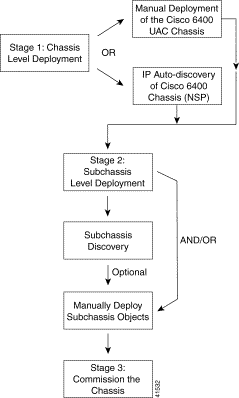
The first stage is deployment at chassis level. The Cisco 6400 chassis can be manually deployed or auto-discovered. You must deploy a Site object for each Cisco 6400 UAC. The second stage is to deploy the SCM objects at subchassis level. This involves auto-discovering the subchassis or deploying additional subchassis objects manually.
The Cisco 6400 SCM software uses a Deployment Wizard to help simplify the process of manually deploying (or creating) new objects representing the network elements to be managed. The Deployment Wizard appears as a series of windows. Each Wizard window prompts you for the information that is required by the deployment process to deploy your new object.
Table 4-1 lists the various objects that can be deployed and the objects they can be deployed from. For example, you could deploy a Chassis and associated NSP from a Site object.
| Object(s) Type to be Deployed | Launch Point to Deploy Object(s) From | Menu Options to Select to Launch Deployment Wizard | |||||
|---|---|---|---|---|---|---|---|
| Cisco 6400 Views | Shelf/Site | Chassis | NSP | NRP | Node Line Card (NLC) | ||
Generic Objects | Yes | Yes | Yes | Yes | Yes | Yes | Deployment, Deploy Generic Objects... |
Shelf, Chassis and NSP | No | Yes | No | No | No | No | Deployment, Cisco 6400 UAC, Deploy Chassis and NSP |
NRP and associated Port | No | No | No | Yes | No | No | Deployment, Cisco 6400 UAC, Deploy NRP(s) and associated Port(s) |
NLC and associated Ports | No | No | No | Yes | No | No | Deployment, Cisco 6400 UAC, Deploy Line Card(s) and associated Port(s) |
Generic objects are non-technology specific objects. The Cisco 6400 SCM allows the following generic objects to be deployed: Bay, IP Device, Network, Region, SNMP Agent, SNMP MIB-2 Agent, SNMP Proxied Device, and Site.
When deploying a generic object, the information you are prompted to provide differs according to the type and number of generic objects you are deploying.
This section explains the deployment of a Site object as an example. The deployment process differs slightly for other types of generic object.
To deploy a Generic object, follow these steps:
Step 2 Click and hold down the right mouse button.
Step 3 Select the Deploy, Generic Object option.
The Deployment Wizard - Templates window appears (see Figure 4-2) displaying a list of available generic object deployment profiles. Deployment profiles are templates that prompt you for the appropriate information required to deploy the selected object successfully.
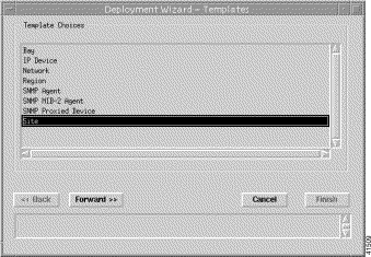
Step 4 Select the generic object that you wish to deploy from the list supplied. The example in Figure 4-2 shows a Site object deployment profile selected. The Deployment Wizard now steps through a series of windows that prompt you for the information required to deploy a Site object.
Step 5 Click Forward. The Deployment Wizard - Object Parameters window appears (see Figure 4-2).
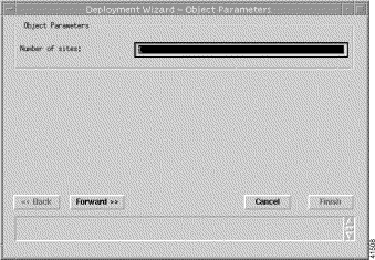
Step 6 Enter the number of Sites required.
 |
Note The information that you supply differs according to the type of generic object you are deploying. More than one Deployment Wizard - Object Parameters window can appear depending upon the type of generic object you are deploying. When deploying more that generic object of the same type you will have to enter the Object Parameters for each object. |
Step 7 Click Forward.
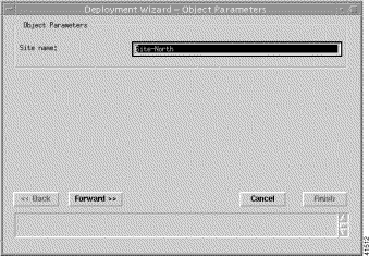
Step 8 Enter a Site name.
Step 9 Click Forward.
The Deployment Wizard - Views window appears (see Figure 4-5).
 |
Note Proceed to Step 17 when deploying a Network or Region object. |
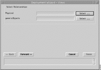
The Deployment Wizard - Views window allows you to select where your new objects are placed in the Physical and genericObject views.
Step 10 Click Select (in the Select Relationships frame) to select a Physical relationship. This step only applies when the launch point was not a generic object, otherwise the generic object is selected as the parent object, for example, a region. The Object Selector window may appear (see Figure 4-6) with the Physical view displayed:
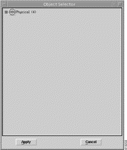
Step 11 Select a location in the Physical view to place the generic object (when required).
Step 12 Click Apply. The Deployment Wizard - Views window appears with your selection displayed. The Cisco 6400 SCM automatically adds the same selection into the genericObjects box. Proceed to Step 14 when the selections are the same. When the Physical and genericObjects selections are different proceed to Step 11.
Step 13 Click Select (in the Select Relationships frame) to select a genericObjects relationship, when required. The Object Selector window appears with the genericObjects view displayed.
Step 14 Select a location in the genericObjects view to place the genericObject.
Step 15 Click Apply. The Deployment Wizard - Views window appears.
Step 16 Click Forward.
 |
Note Repeat Steps 8 to 16 if you entered more than one Site in Step 6. |
The Summary details appear in the Deployment - Wizard Summary window.
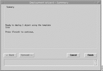
Step 17 Click Finish (when the Deployment Summary information is correct) to complete deployment and close the Deployment Wizard - Summary window. The new objects are created and displayed in the Map Viewer window.
 |
Note This deployment procedure can be applied to the deployment of any of the generic objects although all of the steps may not apply to the particular generic object that you are deploying. |
 |
Note A Cisco 6400 chassis and NSP card must be deployed under a Shelf object. A shelf object is automatically deployed when you deploy a chassis and NSP objects. |
Two node switch processor cards (NSPs) can be deployed in either or both of two dedicated slots (0A and 0B) in the centre of the Cisco 6400 chassis. One NSP is required for system operation, the second NSP provides fault tolerance.
To deploy a Cisco 6400 shelf, chassis and NSP, follow these steps:
 |
Note You can now deploy a number of Cisco 6400 chassis into a unique site or bay, however, you must have one shelf object deployed for each chassis. A shelf object is automatically deployed when you deploy a chassis object. |
Step 2 Click and hold down the right mouse button.
Step 3 Select the Deploy, Cisco 6400 UAC, Deploy Cisco 6400 UAC option. The Deployment Wizard - Object Parameters window (1 of 3) appears (see Figure 4-8).
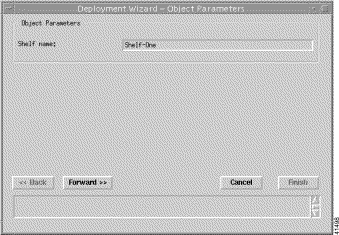
Step 4 Enter a Shelf name. A Shelf is an object that acts as a container for a chassis objects. Each Site object must have a unique name for deployment to be successful.
Click Forward. The Deployment Wizard - Object Parameters window (2 of 3) appears (see Figure 4-9).
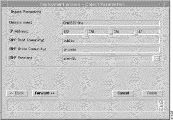
Step 5 Enter a Chassis name, IP Address (for the primary NSP), SNMP Read Community, the SNMP Write Community and select an SNMP Version.
Step 6 Click Forward. The Deployment Wizard - Object Parameters window (3 of 3) appears (see Figure 4-10).
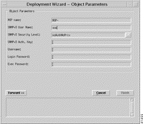
Step 7 Click Forward. The Deployment Summary details appear in the Deployment Summary Screen.
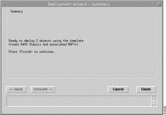
Step 8 Click Finish (when the Deployment Summary information is correct) to complete the deployment and close the Deployment Summary Screen. This creates the relevant objects in the Cisco EMF.
Auto-discovery is used to discover an existing network. The network is examined for IP and SNMP devices and an object created for each new device discovered.
Auto-discovery is also used to identify new SCM chassis and NSP cards within that chassis.
The Auto-discovery application has three mechanisms for discovering devices:
Auto-discovery can detect devices on more than one subnetwork using multi-hop discovery. It can be scheduled to run at preset times. An option is available to specify the physical location under which discovered objects are created. Refer to the Cisco Element Management Framework User Guide for full details.

After the Cisco 6400 UAC is detected, an object representing a shelf, chassis, and an NSP card are created and placed under the Site from which auto-discovery was launched, along with a map of the chassis. (See Figure 4-12.)
 |
Note When auto-discovery is launched from a Site object, the process automatically populates the Physical View. When auto-discovery is selected from any other object you must select the physical view that you require. |
 |
Note Before attempting to commission a chassis, you must set the CLI passwords in the Cisco 6400 NSP Management window (Configuration tab). See the "Cisco 6400 NSP Management Window" section for further details. Failure to set the CLI passwords causes subchassis-discovered NRPs to enter the alarmed state, leaves them decommissioned and their IP addresses are not set. NRP passwords must also be set before using the Service, Subscriber options on the Cisco 6400 SCM. |
Commissioning a chassis within a shelf initiates subchassis discovery. Subchassis discovery discovers all of the cards installed in the chassis being commissioned.
 |
Note Objects that are pre-provisioned but not in the chassis are shown as decommissioned (hatched). Any objects that are discovered but not pre-provisioned are created as new objects. |
A selected chassis can be commissioned in two ways:
To commission a chassis (from the Chassis Configuration window), follow these steps:
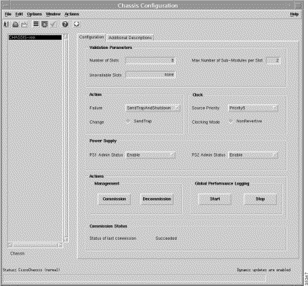
Step 2 Select an appropriate Chassis from the Chassis list displayed at the left side of the Chassis Configuration window.
Step 3 Configure the parameters displayed on the Configuration tab, as required.
 |
Note Validation Parameters are set at the time of deployment and represent the correct number of slots or subslots in the Cisco 6400 chassis. Changing these parameters will mean that slot restriction tests could fail deployment, for example, setting the number of slots to 7 and then attempting to deploy a card in slot 8. |
Step 4 Enter Additional Descriptions when required (optional) on the Additional Descriptions tab. Descriptions 1 and 2 (optional) allow you to specify additional description information for a selected chassis. The Description 1 and Description 2 data entry fields allow you to enter any additional text descriptions for identification purposes, for example, CLLI codes could be entered.
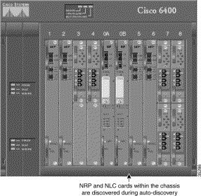
Step 5 Click Commission on the Configuration tab. Subchassis discovery starts and all cards that were not pre-provisioned are discovered and added to the chassis Map Viewer. The NSP and all related cards are now in a commissioned state. Figure 4-14 shows an example view of the chassis after subchassis discovery.
 |
Note Release 2.0.x of the Cisco 6400 SCM does not show redundant Cisco 6400 NSPs, or other elements. |
A selected chassis can be decommissioned in two ways:
To decommission a chassis (from the Chassis Configuration window), follow these steps:
Step 2 Select an appropriate Chassis from the Chassis list displayed at the left side of the Chassis Configuration window.
Step 3 Click Decommission. The state of the selected chassis and all related cards changes to decommissioned.
The Cisco 6400 SCM software provides a Deployment Wizard to assist you to manually deploy subchassis objects.
The Deployment Wizard is the graphical interface used to create new objects representing the network elements to be managed. The Deployment Wizard prompts you to enter the information that is required by the deployment process.
Node route processor cards (NRPs) can be installed in any one or all of the eight chassis slots numbered 1 to 8. Figure 4-14 shows four NRPs installed in chassis slots 1, 2, 5 and 6.
To deploy an NRP and Port, follow these steps:
Step 2 Click and hold down the right mouse button.
Step 3 Select the Deployment, Cisco 6400 UAC, Deploy NRPs and Associated Port(s) option. The Deployment Wizard - Object Parameters (1 of 3) window (see Figure 4-15) appears.
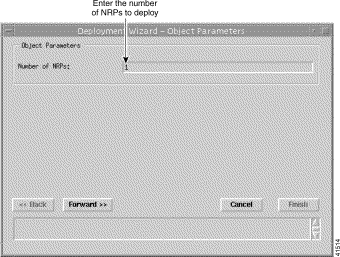
Step 4 Enter the Number of NRPs you wish to deploy. The number of NRPs you can deploy in the selected chassis is dependant upon the number of line cards installed.
Step 5 Click Forward. The Deployment Wizard - Object Parameters (2 of 3) window (see Figure 4-16) appears.
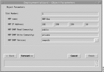
Step 6 Enter a Slot Number, NRP Name, NRP IP Address, NRP SNMP Read Community, NRP SNMP Write Community. Select an NRP SNMP Version.
Step 7 Click Forward. The Deployment Wizard - Object Parameters (3 of 3) window (see Figure 4-17) appears.
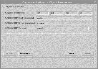
Step 8 Enter a Chassis IP Address, Chassis SNMP Read Community, Chassis SNMP Write Community. Select a Chassis SNMP Version in the Object Parameters panel.
Step 9 Click Forward.
Step 10 Repeat steps 6 to 9 for the Number of NRPs entered in step 4. The Deployment Summary details appear in the Deployment Wizard - Summary window. (see Figure 4-18)
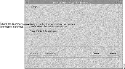
Step 11 Click Finish (when the Deployment Summary information is correct).
Half-height node line cards (NLCs) can be installed in any one or all of the eight slots numbered 1 to 8. One or two OC3 NLCs can be installed in each slot, for a maximum of 16 per chassis.
To deploy an OC3 Node Line Card and Ports, follow these steps:
Step 2 Click and hold down the right mouse button.
Step 3 Select the Deployment, Cisco 6400 UAC, Deploy OC3 Line Card(s) and associated Port(s) option. The Deployment Wizard - Object Parameters (1 of 2) window (see Figure 4-19) appears.
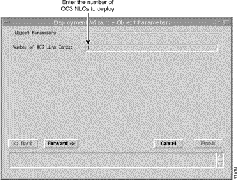
Step 4 Enter the Number of OC3 Node Line Cards you wish to deploy.
Step 5 Click Forward. The Deployment Wizard - Object Parameters (2 of 2) window (see Figure 4-20) appears.
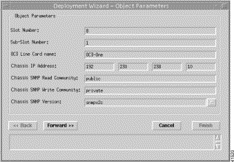
Step 6 Enter a Slot Number, Sub-Slot Number, OC3 Node Line Card Name, Chassis IP Address, Chassis SNMP Read Community, Chassis SNMP Write Community. Select a Chassis SNMP Version.
 |
Note You must enter an unused Slot and Sub-Slot number or deployment will fail. |
Step 7 Click Forward.
Step 8 Repeat steps 6 and 7 for the Number of OC3 Node Line Cards entered in step 4.
The Deployment Summary details appear in the Deployment Summary Screen.
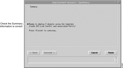
Step 9 Click Finish (when the Deployment Summary information is correct).
The OC12 Node Line Card occupies a full slot in the chassis and has a single port.
To deploy an OC12 Node Line Card and Ports, follow these steps:
Step 2 Click and hold down the right mouse button.
Step 3 Select the Deployment, Cisco 6400 UAC, Deploy OC12 Line Card(s) and associated Port(s) option. The Deployment Wizard - Object Parameters (1 of 2) window (see Figure 4-22) appears.
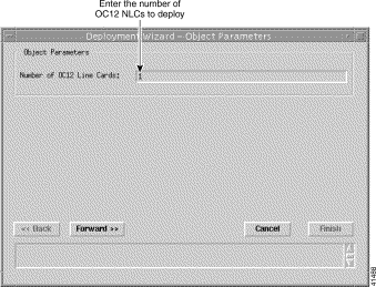
Step 4 Enter the Number of OC12 Node Line Cards you wish to deploy.
Step 5 Click Forward. The Deployment Wizard - Object Parameters (2 of 2) window (see Figure 4-23) appears.
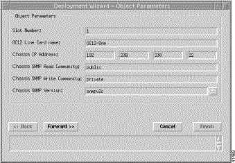
Step 6 Enter a Slot Number, OC12 Node Line Card Name, Chassis IP Address, Chassis SNMP Read Community, Chassis SNMP Write Community. Select a Chassis SNMP Version.
Step 7 Click Forward.
Step 8 Repeat steps 6 and 7 for the Number of OC12 Node Line Cards entered in step 4.
The Deployment Summary details appear in the Deployment Summary Screen.
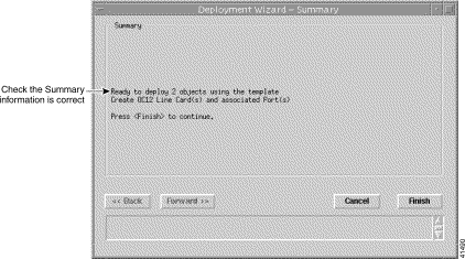
Step 9 Click Finish (when the Deployment Summary information is correct).
Half-height node line cards (NLCs) can be installed in any one or all of the eight slots numbered 1 to 8. One or two NLCs can be installed in each slot, for a maximum of 16 per chassis.
To deploy DS3 Node Line Cards and Ports, follow these steps:
Step 2 Click and hold down the right mouse button.
Step 3 Select the Deployment, Cisco 6400 UAC, Deploy DS3 Line Card(s) and associated Port(s) option. The Deployment Wizard - Object Parameters (1 of 2) window (see Figure 4-25) appears.
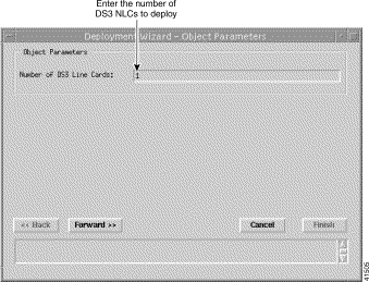
Step 4 Enter the Number of OC3 Node Line Cards you wish to deploy.
Step 5 Click Forward. The Deployment Wizard - Object Parameters (2 of 2) window (see Figure 4-26) appears.
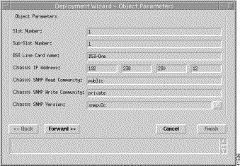
Step 6 Enter a Slot Number, Sub-Slot Number, DS3 Node Line Card Name, Chassis IP Address, Chassis SNMP Read Community, Chassis SNMP Write Community. Select a Chassis SNMP Version.
 |
Note You must enter an unused Slot and Sub-Slot number or deployment will fail. |
Step 7 Click Forward.
Step 8 Repeat steps 6 and 7 for the Number of DS3 Node Line Cards entered in step 4. The Deployment Summary details appear in the Deployment Summary Screen.
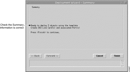
Step 9 Click Finish (when the Deployment Summary information is correct).
![]()
![]()
![]()
![]()
![]()
![]()
![]()
![]()
Posted: Fri Aug 4 01:46:10 PDT 2000
Copyright 1989-2000©Cisco Systems Inc.