|
|

This document provides information about installing an optional Cisco 6100 Series rear door. The rear door attaches to the back of the multiplexer chassis (MC) and restricts access to the backplane and cable connectors. To keep cables from interfering with the opening of the rear door, the cables that come down from the top of the rack can be tie wrapped to the door-mounting brackets.
The rear door accessory kit contains one door-mounting bracket (detached), one door-mounting bracket (with the rear door attached), ten tie wraps, and six standoff screws.
This document includes the following sections:
The following tools and equipment are required for installation of the Cisco 6100 Series rear door:
A second person may be helpful when you are installing the rear door. The door-mounting bracket (with the rear door attached) may be difficult for one person to maneuver.
 | Caution Proper ESD protection is required whenever you handle Cisco DSLAM equipment. Installation and maintenance personnel should be properly grounded using ground straps to eliminate the risk of ESD damage to the equipment. Modules are subject to ESD damage whenever they are removed from the chassis. |
 | Caution Be careful when removing the screws and reinserting the standoff screws and backplane screws into the screw holes on the backplane so that the backplane circuitry does not become damaged. |
 | Caution Use caution when installing or modifying telephone lines. |
 | Warning Systems using a Cisco 6100 backplane must connect to the network through a POTS splitter chassis (PSC) to provide the secondary lightning protection required by NEBS. |
 | Warning Installation and maintenance should be performed only by trained service personnel who are aware of the potential hazards involved (for example, fire and electric shock). |
 | Warning To prevent a Cisco 6100 Series system from overheating, do not operate it in an area that exceeds the maximum recommended ambient temperature of 104°F (40°C) in a CO location. |
 | Warning Two people are required to lift the chassis. Grasp the chassis underneath the lower edge and lift with both hands. To prevent injury, keep your back straight and lift with your legs, not your back. |
 | Warning To prevent bodily injury when mounting or servicing this unit in a rack, you must take special precautions to ensure that the system remains stable. The following guidelines are provided to ensure your safety: |
 | Warning Never touch un-insulated telephone wires or terminals unless the telephone line has been disconnected at the network interface. |
 | Warning Do not use this product near water. For example, near a bath tub, wash bowl, kitchen sink or laundry tub, in a wet basement, or near a swimming pool. |
When installing the rear door, be sure that you follow the installation procedures in proper sequence. Table 1 is a checklist of the installation steps in the order in which they should occur.
 | Caution Proper ESD protection is required whenever you handle Cisco DSLAM equipment. Installation and maintenance personnel should be properly grounded using ground straps to eliminate the risk of ESD damage to the equipment. Modules are subject to ESD damage whenever they are removed from the chassis. |
| Check | Installation Step |
|---|---|
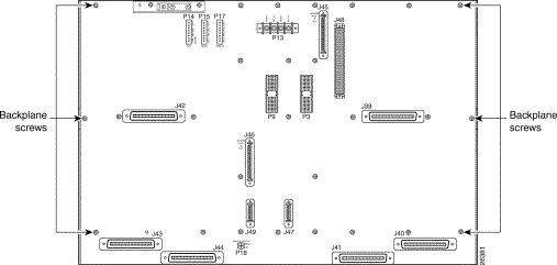
| Step 1. Locate and remove the six required backplane screws. |
| Step 2. Install the six standoff screws. |
| Step 3. Install the door-mounting bracket on the right side of the chassis using the screws removed in Step 1. |
| Step 4. Install the door-mounting bracket (with the rear door attached) on the left side of the chassis using the screws removed in Step 1. |
| Step 5. Tie wrap cables to the door-mounting bracket loops as necessary. |
| Step 6. Close and latch the rear door. |
| Step 7. Align the thumbscrews and thumbscrew fasteners to secure the rear door. |
Following are the detailed steps for installing the rear door:

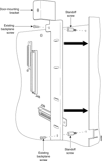
Step 2 The six standoff screws screw into the locations formerly occupied by the six screws you just removed in Step 1. Install the six standoff screws. Use a one-quarter inch socket driver or wrench to tighten the standoff screws.
Step 3 Facing the rear of the chassis, install the door-mounting bracket on the right side of the chassis. Place the bracket over the standoff screws. Use three of the screws you removed in Step 1 to fasten the door-mounting bracket to the chassis. (See Figure 2.)

Step 4 Facing the rear of the chassis, install the door-mounting bracket (with the rear door attached) on the left side of the chassis. Place the bracket (with rear door) over the standoff screws. Use three of the screws you removed in Step 1 to fasten the door-mounting bracket (with rear door) to the chassis.
Step 5 Use the tie wraps provided in the accessory kit to attach cables to the door-mounting bracket loops, as necessary.
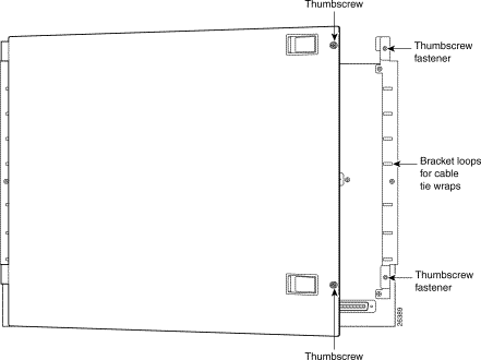
Step 6 The rear door closes left to right (seen from the rear of the chassis). There are two latches on the rear door (see Figure 3). Lift the latches as you close the rear door. Once the rear door is in place, release the latches.

Step 7 The two thumbscrews located on the rear door align with two thumbscrew fasteners on the bracket (see Figure 4). Tighten the thumbscrews to secure the rear door.

Use the following related documentation with the Cisco 6100 Series system:
Cisco Connection Online (CCO) is Cisco Systems' primary, real-time support channel. Maintenance customers and partners can self-register on CCO to obtain additional information and services.
Available 24 hours a day, 7 days a week, CCO provides a wealth of standard and value-added services to Cisco's customers and business partners. CCO services include product information, product documentation, software updates, release notes, technical tips, the Bug Navigator, configuration notes, brochures, descriptions of service offerings, and download access to public and authorized files.
CCO serves a wide variety of users through two interfaces that are updated and enhanced simultaneously: a character-based version and a multimedia version that resides on the World Wide Web (WWW). The character-based CCO supports Zmodem, Kermit, Xmodem, FTP, and Internet e-mail, and it is excellent for quick access to information over lower bandwidths. The WWW version of CCO provides richly formatted documents with photographs, figures, graphics, and video, as well as hyperlinks to related information.
You can access CCO in the following ways:
For a copy of CCO's Frequently Asked Questions (FAQ), contact cco-help@cisco.com. For additional information, contact cco-team@cisco.com.
Cisco documentation and additional literature are available in a CD-ROM package, which ships with your product. The Documentation CD-ROM, a member of the Cisco Connection Family, is updated monthly. Therefore, it might be more current than printed documentation. To order additional copies of the Documentation CD-ROM, contact your local sales representative or call customer service. The CD-ROM package is available as a single package or as an annual subscription. You can also access Cisco documentation on the World Wide Web at http://www.cisco.com, http://www-china.cisco.com, or http://www-europe.cisco.com.
If you are reading Cisco product documentation on the World Wide Web, you can submit comments electronically. Click Feedback in the toolbar and select Documentation. After you complete the form, click Submit to send it to Cisco. We appreciate your comments.
![]()
![]()
![]()
![]()
![]()
![]()
![]()
![]()
Posted: Wed Jul 24 23:37:41 PDT 2002
All contents are Copyright © 1992--2002 Cisco Systems, Inc. All rights reserved.
Important Notices and Privacy Statement.