|
|

This document tells you how to (1) migrate from a Cisco 6100 chassis to a Cisco 6130 chassis and (2) install a Cisco 6100 Series system, using the Cisco 6130 chassis.
The Cisco 6130 Advanced Digital Subscriber Line Access Multiplexer (DSLAM) is a carrier class multiplexer. It functions in either of two configurations:
The Cisco 6130 sends and receives subscriber data (often Internet service) over existing copper telephone lines, concentrating all traffic onto a single high-speed trunk for transport to the Internet or corporate intranet. ADSL and SDSL customer premises equipment (CPE) devices, which are connected to PCs or routers at the subscriber site, modulate data so that the data can travel over telephone lines to the Cisco 6130 Advanced DSLAM at the central office (CO).
This document includes the following sections:
The Cisco 6130 multiplexer chassis (MC) has 38 module slots. These include
 | Caution Do not mix CAP ATU-C, DMT-2 ATU-C, and STU-C modules in the same Cisco 6130 chassis. Mixing modules can cause unpredictable system behavior. |
Figure 1 identifies the MC module slots.

In a Direct Connect configuration where DMT-2 ATU-C modules are used, you must install a fan tray directly beneath the MC and leave one rack unit space below the fan tray. For more information on the fan tray, refer to the Cisco 6100 Series Fan Tray Configuration Notes.
The following tools and equipment are required for chassis installation or removal:
Two people are needed for lifting the chassis and installing it.
 | Caution Proper ESD protection is required whenever you handle Cisco DSLAM equipment. Installation and maintenance personnel should be properly grounded using ground straps to eliminate the risk of ESD damage to the equipment. Modules are subject to ESD damage whenever they are removed from the chassis. |
 | Caution Do not mix CAP ATU-C, DMT-2 ATU-C, and STU-C modules in the same Cisco 6130 chassis. Mixing modules can cause unpredictable system behavior. |
 | Caution Be careful when removing the standoff screws and reinserting the screws into the screw holes on the backplane so that the backplane circuitry does not become damaged. |
 | Caution If you do not pull the modules away from the backplane connection before applying power, you could damage the modules and the chassis. |
 | Caution Reseating the modules in the chassis with the power leads reversed may damage the modules. |
 | Caution Use caution when installing or modifying telephone lines. |
 | Warning Systems using a Cisco 6100 backplane must connect to the network through a POTS splitter chassis (PSC) to provide the secondary lightning protection required by NEBS. |
 | Warning Installation and maintenance should be performed only by trained service personnel who are aware of the potential hazards involved (for example, fire and electric shock). |
 | Warning To prevent a Cisco 6100 Series system from overheating, do not operate it in an area that exceeds the maximum recommended ambient temperature of 104°F (40°C) in a CO location. |
 | Warning Two people are required to lift the chassis. Grasp the chassis underneath the lower edge and lift with both hands. To prevent injury, keep your back straight and lift with your legs, not your back. |
 | Warning To prevent bodily injury when mounting or servicing this unit in a rack, you must take special precautions to ensure that the system remains stable. The following guidelines are provided to ensure your safety: |
 | Warning Never touch uninsulated telephone wires or terminals unless the telephone line has been disconnected at the network interface. |
 | Warning Do not use this product near water. For example, near a bath tub, wash bowl, kitchen sink or laundry tub, in a wet basement, or near a swimming pool. |
There are two different backplanes available with the Cisco 6100 Series system: the Cisco 6130 and the Cisco 6100. The Cisco 6130 backplane is supported in Release 2.4.0 or higher. Table 1 shows the configurations in which each of these backplanes can be used.
| Direct Connect with PSC Configuration | Direct Connect without PSC Configuration | DOH Configuration5 | |||
|---|---|---|---|---|---|
| With a Cisco PSC | With a Siecor POTS Splitter1 | With an LCC2 | With a Cisco PSC | ||
Cisco 6130 backplane3 | Yes | Yes4 | Yes | Yes | Yes |
Cisco 6100 backplane | Yes5 | No | No6 | Yes | Yes |
Table 2 shows backplane compatibility with various Cisco 6100 Series system releases.
| Cisco 6100 Series System Releases | |||||
|---|---|---|---|---|---|
| Release 2.4.0 | Release 2.3.1 | Release 2.3.0 | Release 2.2.1/2.2.5 | Release 2.2.0 | |
Cisco 6130 backplane | Yes | Yes | Yes | Yes | Yes |
Cisco 6100 backplane1 | Yes | Yes | Yes | Yes | Yes |
Table 3 shows the configurations where the two Cisco 6100 Series backplanes can operate.
| Module | Direct Connect with a PSC Configuration | Direct Connect without a PSC Configuration | DOH Configuration | Siecor POTS Splitter1 | |||
|---|---|---|---|---|---|---|---|
| Cisco 6130 Backplane | Cisco 6100 Backplane | Cisco 6130 Backplane | Cisco 6100 Backplane | Cisco 6130 Backplane | Cisco 6100 Backplane | ||
Dual-port CAP ATU-C | Yes2 | Yes | No | Not supported | Yes2 | Yes | No |
Dual-port DMT-2 ATU-C | Yes3 | Not tested | Yes3 | Not supported | No | Not tested | Yes |
Quad-port STU-C | No | No | Yes4 | Not supported | No | No | No |
Figure 2 shows the Cisco 6130 backplane of the MC. This backplane ships with Release 2.4.0 and replaces the Cisco 6100 backplane. The Cisco 6130 supports
To determine if you have the Cisco 6130, look for the J49 connector on the backplane. (See Figure 2.) The Cisco 6100 backplane does not have this connector.
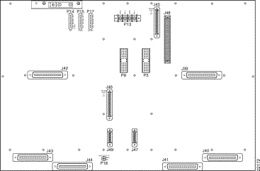
Table 4 lists the connectors on the backplane of the Cisco 6130.
| Identifier | Name | Description |
|---|---|---|
J45 | Modem pool A out | A 68-pin SCSI2 connector used to connect to the LCC for ATU-C pool A. Note Use for DOH configurations only. |
J46 | Modem pool B out | A 68-pin SCSI2 connector used to connect to the LCC for ATU-C pool B. Note Use for DOH configurations only. |
J47 | LCC controller out | A 26-pin SCSI connector used to connect to the LCC controller in connectors on the LCC. Note Use for DOH configurations only. |
J48 | DS3 subtending module | A 96-pin DIN connector. |
J49 | — | Note For future use. |
J39, J40, J41, J42, J43, J44 | Data | Six 50-pin Champ connectors used to transfer data between the MC and the PSC in a Direct Connect with a PSC configuration. In a Direct Connect without a PSC configuration, the connectors are used to transfer data between the MC and the CPE equipment. Note These connectors are not used in a DOH configuration. |
P9, P3 | System I/O card | Two 2-mm HM hard metric modular connectors (male on the MC and female on the system I/O card) used to connect the system I/O card. |
P13 | Power | A terminal block connector with four dual power input connections (48 V A, 48 V A Return, 48 V B, and 48 V B Return). |
P14, P15, P17 | Alarm | Three 8-position headers providing connections for E2A, visual. and audible alarm contacts. Note If you are using DMT-2 ATU-C modules, the fan tray alarm contacts (P14, pins 7 and 8) must be connected so that fan tray alarms can be transmitted to ViewRunner. |
P18 | Analog test input | A 2-position header for connecting external ADSL test equipment. |
This section provides cabling diagrams for the three Cisco 6130 configurations:
Figure 3 shows the basic cabling of the Cisco 6130 Direct Connect with a PSC configuration.
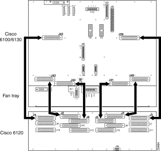
Figure 4 shows the basic cabling of the Cisco 6130 Direct Connect without a PSC configuration.
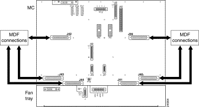
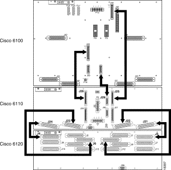
Figure 5 shows the basic cabling of the Cisco 6130 DOH configuration.
Use the procedures in this section to remove a chassis with a Cisco 6100 backplane and replace it with a chassis with a Cisco 6130 backplane.
 | Caution Proper ESD protection is required whenever you handle Cisco DSLAM equipment. Installation and maintenance personnel should be properly grounded using ground straps to eliminate the risk of ESD damage to the equipment. Modules are subject to ESD damage whenever they are removed from the chassis. |
To replace your current Cisco 6100 chassis with the new Cisco 6130 chassis, you will need to remove the Cisco 6100 MC and replace it with the Cisco 6130 MC. Use the following steps to remove a Cisco 6100 MC:
Step 2 Disconnect the ViewRunner PC from the MC by removing the Ethernet cable.
Step 3 Open the MC front door.
Step 4 Power down the system.
Step 5 If you have an OC-3c NI module installed, you will need to disconnect the OC-3c NI module from the network.
(a) Disconnect the optical fiber to the transmit and receive connectors in the inset on the front panel of the OC-3c NI modules and pull the fiber through.
(b) To remove the OC-3c NI module from slot 10 on the MC, lift up on the ejector tab and carefully slide the module out of the chassis.
Step 6 If you have a DS3 NI module installed, you will need to disconnect the DS3 NI module from the network.
(a) Disconnect the cable from the ATM switch to the BNC connectors on the system I/O card, which is located on the MC backplane. The bottom BNC connector (J4, the closest to the Ethernet connector) is for receive, and the top connector (J3) is for transmit.
(b) To remove the DS3 NI module from slot 10 on the MC, lift up on the ejector tabs and carefully slide the module out of the chassis.
Step 7 If you are running a subtended network
(a) On the subtending host backplane, disconnect the transmit and receive connectors from DS3 subtending card subtending. (See Figure 6 for cable locations.)
(b) On the subtended node backplane, disconnect the transmit and receive connectors from the system I/O card. (See Figure 6 for cable locations.)

(c) To remove the DS3 NI module from slot 10 of the subtended node MC, lift up on the ejector tab and carefully slide the module out of the chassis.
(d) To remove the DS3 STM from slot 9 of the subtending host MC, lift up on the ejector tab and carefully slide the module out of the chassis.
(e) To remove the DS3 subtending card from the MC backplane (see Figure 7)
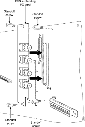
Step 8 Remove the filler faceplates from the open slots in the Cisco 6100.
Step 9 Remove all modules from the Cisco 6100 by lifting up on the each ejector tab and carefully sliding the module out of the chassis.
Step 10 To pull all modules away from the backplane connection in the LCC (if you are using a DOH configuration) and PSC, lift up on the ejector tab and carefully slide each module forward without removing it from the chassis.
Step 11 Remove the system I/O card from the Cisco 6100 backplane.
Step 12 Disconnect the alarm contacts.
Step 13 Disconnect the MC power connections from the fuse and alarm panel.
Step 14 Disconnect the grounding lugs on the MC.
Step 15 Disconnect the DOH switching bus cables (applicable in a DOH configuration).
Step 16 In a Direct Connect with a PSC configuration, disconnect the MC from the PSC. In a DOH configuration, disconnect the MC from the LCC.
Step 17 Remove the MC from the rack.
Now that you have disconnected and removed the chassis with the Cisco 6100 backplane, you are ready to install the chassis with the Cisco 6130 backplane. The following section "Installing an MC with a Cisco 6130 Backplane" documents the installation of the Cisco 6130 chassis.
If you have just removed a Cisco 6100 backplane with chassis, the following sections provide installation procedures for each of the two configurations:
If you are not migrating from a chassis with a Cisco 6100 backplane and are installing a Cisco 6130 chassis for the first time, refer to the "Installing the Cisco 6130" section for installation procedures.
When installing a Direct Connect with a PSC configuration, be sure that you follow the installation procedures in proper sequence. For more detailed installation procedures, cabling information, and rack requirements refer to the Cisco 6100 Series Direct Connect Installation Guide.
Use these installation steps when you are installing a chassis with a Cisco 6130 backplane in a Direct Connect with a PSC configuration:
For more information on the fan tray, refer to the Cisco 6100 Series Fan Tray Configuration Notes.
Step 2 If you are using DMT-2 ATU-C modules, install the fan tray in the rack.
Step 3 Install the new MC with the Cisco 6130 backplane in the rack.
Step 4 Connect the MC to the PSC.
Step 5 Ground the MC.
Step 6 If you are using DMT-2 modules, ground the fan tray.
Step 7 Attach the MC power connections to the fuse and alarm panel.
Step 8 If you have installed a fan tray, attach the fan tray power connections to the fuse and alarm panel.
Step 9 Connect the alarm contacts. The fan tray alarm contacts (P14, pin 7 and 8) must be connected so that the fan tray alarms can be transmitted to ViewRunner.
Step 10 Install the system I/O card and the DS3 subtending card (applicable in a subtending network) on the backplane of the MC. For detailed installation information, refer to the Cisco 6100 Series Direct Connect Installation Guide.
Step 11 Verify that all modules in the PSC are pulled away from the backplane connection.
Step 12 Apply power to the system.
Step 13 Install or reseat the modules in the following order:
(a) To install the ATU-C modules in the MC, do the following:
(b) To install the NI module in the MC, do the following:
(c) To reseat the POTS splitter modules in the PSC, do the following:
(d) To install the STM in the MC, do the following:
(e) To install the SC module in the MC, do the following:
Step 14 Install the filler faceplates in open slots.
Step 15 Install a subtended network (optional).
Step 16 Connect the NI module to the network.
Step 17 Verify that the MC front door is closed.
Step 18 Connect the ViewRunner PC to the MC (Ethernet).
Step 19 Install the rear door (optional).
Step 20 Run the connection test procedures.
When installing a DOH configuration, be sure that you follow the installation procedures in proper sequence. For more detailed installation procedures, cabling information, and rack requirements refer to the Cisco 6100 Series Digital Off-Hook Installation Guide.
Use these installation steps when you are installing a chassis with a Cisco 6130 backplane in a DOH configuration:
Step 2 Install the new MC with the Cisco 6130 backplane in the rack.
Step 3 Install the air and heat deflector above the MC.
Step 4 Connect the LCC controller out 26-pin SCSCI connector (J47) on the MC to the LCC controller in 26-pin SCSI connector (J49) on the LCC.
Step 5 Connect the DOH data-switching bus cables. Connect J45 on the MC to J25 on the LCC. Connect J46 on MC to J26 on LCC.
Step 6 Ground the MC.
Step 7 Attach the MC power connections to the fuse and alarm panel.
Step 8 Connect the alarm contacts. The fan tray alarm contacts (P14, pins 7 and 8) must be connected so that the fan tray alarms can be communicated to ViewRunner.
Step 9 Install the system I/O card and the DS3 subtending card (applicable in a subtending network) on the backplane of the MC. For detailed installation information, refer to the Cisco 6100 Series Digital Off-Hook Installation Guide.
Step 10 Verify that all modules in the LCC and PSC are pulled away from the backplane connection.
Step 11 Apply power to the system.
Step 12 Install or reseat the modules in the following order:
(a) To install the ATU-C modules in the MC, do the following:
(b) To install the NI module in the MC, do the following:
(c) To reseat the POTS splitter modules in the PSC, do the following:
(d) To install the STM in the MC, do the following:
(e) To reseat the LIM controller module in the LCC, do the following:
(f) To reseat the LIMs in the LCC, do the following:
(g) To install the SC module in the MC, do the following:
Step 13 Install the filler faceplates in open slots.
Step 14 Install a subtended network (optional).
Step 15 Connect the NI module to the network.
Step 16 Verify that the MC front door is closed.
Step 17 Connect the ViewRunner PC to the MC (Ethernet).
Step 18 Install the rear door (optional).
Step 19 Run the connection test procedures.
If you are not migrating from a chassis with a Cisco 6100 backplane to a chassis with a Cisco 6130 backplane, use the following sections, which provide installation procedures for each of the three configurations:
For information on rack requirements, refer to the Cisco 6100 Series Direct Connect Installation Guide or the Cisco 6100 Series Digital Off-Hook Installation Guide, depending on your configuration.
 | Caution Proper ESD protection is required whenever you handle Cisco DSLAM equipment. Installation and maintenance personnel should be properly grounded using ground straps to eliminate the risk of ESD damage to the equipment. Modules are subject to ESD damage whenever they are removed from the chassis. |
When installing a Direct Connect with a PSC configuration, be sure that you follow the installation procedures in proper sequence.
Table 5 is an overview of the installation steps used when installing a Direct Connect with a PSC configuration. For more detailed installation procedures, cabling information, and rack requirements refer to the Cisco 6100 Series Direct Connect Installation Guide.
| Check | Installation Step |
|---|---|
| 1. Stabilize and measure rack space. |
| 2. Install the PSC in the rack. |
| 3. Install the fan tray in the rack. |
| 4. Install the MC in the rack. |
| 5. Connect the MC to the PSC. |
| 6. Ground the MC, fan tray, and PSC. |
| 7. Attach the MC power connections to the fuse and alarm panel. |
| 8. Attach the fan tray power connections to the fuse and alarm panel. |
| 9. Connect the alarm contacts. |
| 10. Locate (or install) the system I/O card and the DS3 subtending card (applicable in a subtending network) on the backplane of the MC. |
| 11. Connect the PSC to the MDF1. |
| 12. Verify the CAP ATU-C module jumpering for Direct Connect. |
| 13. Apply power to the system. |
| 14. Install the modules in the MC and PSC, ATU-C modules first. |
| 15. Install the filler faceplates in open slots. |
| 16. Install a subtended network (optional). |
| 17. Connect the NI module to the network. |
| 18. Verify that the MC front door is closed. |
| 19. Connect the ViewRunner PC to the MC (Ethernet). |
| 20. Install the rear door (optional). |
| 21. Run the connection test procedures. |
| 1MDF = main distribution frame |
When installing a Direct Connect without a PSC configuration, be sure that you follow the installation procedures in proper sequence.
Table 6 is an overview of the installation steps used when installing a Direct Connect without a PSC configuration. For more detailed installation procedures, cabling information, and rack requirements refer to the Cisco 6100 Series Direct Connect Installation Guide.
| Check | Installation Step |
|---|---|
| 1. Stabilize and measure rack space. |
| 2. Install the fan tray in the rack. |
| 3. Install the MC in the rack. |
| 4. Connect the MC to the MDF. |
| 5. Ground the MC and fan tray. |
| 6. Attach the MC power connections to the fuse and alarm panel. |
| 7. Attach the fan tray power connections to the fuse and alarm panel. |
| 8. Connect the alarm contacts. |
| 9. Locate (or install) the system I/O card and the DS3 subtending card (applicable in a subtending network) on the backplane of the MC. |
| 10. Apply power to the system. |
| 11. Install the modules in the MC, ATU-C modules first. |
| 12. Install the filler faceplates in open slots. |
| 13. Install a subtended network (optional). |
| 14. Connect the NI module to the network. |
| 15. Verify that the MC front door is closed. |
| 16. Connect the ViewRunner PC to the MC (Ethernet). |
| 17. Install the rear door (optional). |
| 18. Run the connection test procedures. |
When installing a DOH configuration, be sure that you follow the installation procedures in proper sequence.
Table 7 is an overview of the installation steps used when installing a DOH configuration. For more detailed installation procedures and cabling information, refer to the Cisco 6100 Series Digital Off-Hook Installation Guide.
| Check | Installation Step |
|---|---|
| 1. Stabilize and measure rack space. |
| 2. Install the PSC, LCC, and MC in the rack. |
| 3. Install the air and heat deflector in the rack. |
| 4. Connect the LCC to the PSC. |
| 5. Connect the LCC controller to the MC. |
| 6. Connect the DOH data-switching bus. |
| 7. Ground the MC, LCCs, and PSC. |
| 8. Attach the MC and LCC power connections to the fuse and alarm panel. |
| 9. Connect the alarm contacts. |
| 10. Locate (or install) the system I/O card and the DS3 subtending card (applicable in a subtending network) on the backplane of the MC. |
| 11. Use the DIP switches to set the LCC ID for each LCC. |
| 12. Connect the PSC to the MDF. |
| 13. Verify the CAP ATU-C module jumpering for DOH. |
| 14. Apply power to the system. |
| 15. Install the modules in the MC, LCC, and PSC, CAP ATU-C modules first. |
| 16. Install the filler faceplates in open slots. |
| 17. Install a subtended network (optional). |
| 18. Connect the NI module to the network. |
| 19. Verify that the MC front door is closed. |
| 20. Connect the ViewRunner PC to the MC (Ethernet). |
| 21. Install the rear door (optional). |
| 22. Run the connection test procedures. |
Use the following related documentation with the Cisco 6130:
The following ViewRunner management software is used to provision and manage the Cisco 6100 Series system:
The ViewRunner documentation is located on Cisco Connection Online (CCO). You can access the ViewRunner documentation in the following ways:
Cisco Connection Online (CCO) is Cisco Systems' primary, real-time support channel. Maintenance customers and partners can self-register on CCO to obtain additional information and services.
Available 24 hours a day, 7 days a week, CCO provides a wealth of standard and value-added services to Cisco's customers and business partners. CCO services include product information, product documentation, software updates, release notes, technical tips, the Bug Navigator, configuration notes, brochures, descriptions of service offerings, and download access to public and authorized files.
CCO serves a wide variety of users through two interfaces that are updated and enhanced simultaneously: a character-based version and a multimedia version that resides on the World Wide Web (WWW). The character-based CCO supports Zmodem, Kermit, Xmodem, FTP, and Internet e-mail, and it is excellent for quick access to information over lower bandwidths. The WWW version of CCO provides richly formatted documents with photographs, figures, graphics, and video, as well as hyperlinks to related information.
You can access CCO in the following ways:
For a copy of CCO's Frequently Asked Questions (FAQ), contact cco-help@cisco.com. For additional information, contact cco-team@cisco.com.
Cisco documentation and additional literature are available in a CD-ROM package, which ships with your product. The Documentation CD-ROM, a member of the Cisco Connection Family, is updated monthly. Therefore, it might be more current than printed documentation. To order additional copies of the Documentation CD-ROM, contact your local sales representative or call customer service. The CD-ROM package is available as a single package or as an annual subscription. You can also access Cisco documentation on the World Wide Web at http://www.cisco.com, http://www-china.cisco.com, or http://www-europe.cisco.com.
If you are reading Cisco product documentation on the World Wide Web, you can submit comments electronically. Click Feedback in the toolbar and select Documentation. After you complete the form, click Submit to send it to Cisco. We appreciate your comments.
![]()
![]()
![]()
![]()
![]()
![]()
![]()
![]()
Posted: Wed Jul 24 23:38:16 PDT 2002
All contents are Copyright © 1992--2002 Cisco Systems, Inc. All rights reserved.
Important Notices and Privacy Statement.