|
|

This chapter describes how to use the Cisco Customer Premises Equipment (CPE) Commander settings to view and change Cisco 67x device settings. The Cisco CPE Commander works on PC platforms (Windows 2000, Windows NT, Windows 95, and Windows 98) and Macintosh platforms.
After you log in to the Cisco CPE Commander, the Cisco CPE Commander windows appear. Use the Cisco CPE Commander fields and action buttons described in this section to run the CPE Commander software and manage the Cisco 67x device.
On both the PC and the Macintosh platforms, the Cisco CPE Commander contains the following tabs:
The tabs are described in the following sections.
Use the Call tab to view information for a selected connection, including:
Figure 2-1 shows the Call tab as it appears on a PC platform.
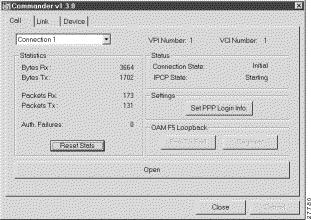
Table 2-1 lists definitions for Call tab fields.
| Field Name | Description |
|---|---|
Connection Selection List | Multiple VCs selectable. Connection 1 is wan 0-0 in the CLI. Connection 2 through 4 (available through drop-down menu) equate to wan 0-1 through wan 0-3. |
VPI for a specific connection. | |
VCI for a specific connection. Ranges from 0 to 3. | |
Number of bytes received for a specified connection. | |
Number of bytes transmitted for a specified connection. | |
Number of packets received for a specified connection. | |
Number of packets transmitted for a specified connection. | |
Auth. Failures | Number of failed attempts at PPP authentication. |
Reset Stats | |
Connection State | The state of the connection. These states are described in Request for Comments (RFC) 1661, The Point-to-Point Protocol (PPP). Options include: Note See RFC 1661 for more information on these states. |
IPCP State | The state of the connection. These states are described in RFC 1661. Options include:
Note See RFC 1661 for more information on these states. Note If CPE is not configured for PPP mode, IPCP state will show <not applicable>. |
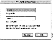
Set PPP Login Info | Opens the PPP Information dialog box. You can change your PPP login name, or your PPP password, or both. |
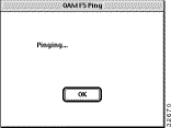
End-To-End | Ping to test end-to-end connection. |
Segment | Ping to test this segment. |
Open/Close | Open/close the selected VC (training up the CPE if necessary). |
The Call tab contains the following action items:
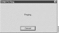
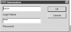
Figure 2-4 shows the Call tab as it appears on a Macintosh platform.
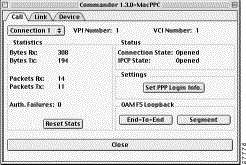
Table 2-2 lists definitions for Call tab fields.
| Field Name | Description |
|---|---|
Connection Selection List | Multiple VCs selectable. Connection 1 is wan 0-0 in the CLI. Connection 2 through 4 (available through drop-down menu) equate to wan 0-1 through wan 0-3. |
VPI for a specific connection. | |
VCI for a specific connection. Ranges from 0 to 3. | |
Number of bytes received for a specified connection. | |
Number of bytes transmitted for a specified connection. | |
Number of packets received for a specified connection. | |
Number of packets transmitted for a specified connection. | |
Auth. Failures | Number of failed attempts at PPP authentication. |
Reset Stats | |
Connection State | The state of the connection. These states are described in RFC 1661. Options include: Note See RFC 1661 for more information on these states. |
IPCP State | The state of the connection. These states are described in RFC 1661. Options include:
Note See RFC 1661 for more information on these states. Note If CPE is not configured for PPP mode, IPCP state will show <not applicable>. |
Set PPP Login Info | Opens the PPP Information dialog box. You can change your PPP login name, or your PPP password, or both. |
End-To-End | Ping to test end-to-end connection. |
Segment | Ping to test this segment. |
Open/Close | Open/close the selected VC (training up the CPE if necessary). |
Use the Link tab to view the following information:
 |
Note The Link tab also displays timer information. The timers shown on the Link tab are set from the CPE command-line interface. Your service provider (SP) can also set timers that cause your connection to time out. To inform you that the SP has terminated your session, the Cisco CPE Commander software displays dialog box messages. |
Figure 2-7 shows the Link tab as it appears on a PC platform.
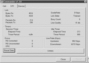
Table 2-3 lists definitions for Link tab fields.
| Field Name | Description |
|---|---|
Bytes Rx | Number of bytes received. |
Number of bytes transmitted. | |
Number of packets received. | |
Number of packets transmitted. | |
Your SP sets this rate. ScalaRate only applies to the upstream rate. | |
Link State | Status of the link between the Cisco 67x device and the central office (CO). Options include:
Note When you train at high rates, the Cisco 67x device flashes the Searching, Training, and Pending link states several times before connecting to the CO equipment. |
Number of times the Cisco 67x device attempted to connect to the CO equipment but could not because the CO equipment was busy. | |
Number between 12 and 45. This number describes the quality of the physical connection between the Cisco 67x device and CO equipment. The higher the number, the better the quality of the physical connection. | |
When the timer type is Session, the Cisco 67x device drops the link when Elapsed Time equals the Timer Period. Note Your SP defines the timer types. | |
Idle Timer | When the timer type is Idle, the Cisco 67x device resets the Elapsed Time field when the link resumes activity. However, if the link remains inactive for the entire Timer Period, the Cisco 67x device drops the link. Note Your SP defines the timer types. |
Elapsed time of the timer type. Varies according to Timer Type. If the Timer Type is:
Note If the Elapsed Time field reads Off, the field is not currently active. | |
Time period that, after elapsed, cues the Cisco 67x device to drop the link. Varies according to Timer Type. If the Timer Type is:
Note If the Timer Period field reads Off, the field is not currently active. | |
Specifies the number of Reed-Solomon Corrected errors. Reed-Solomon is an Error Correction Code (ECC) that allows data that is being read or transmitted to be checked for errors and, if necessary, corrected immediately. | |
Specifies the number of Reed-Solomon uncorrected errors. | |
Cyclic Redundancy Check. Indicates that an error occurred during a transmission. Note It is normal for your system to exhibit a small number of CRC errors. | |
Downstream line rate. | |
Untrain/Train | Untrain (any VCs opened on the Call tab will be closed). |
Figure 2-8 shows the Link tab as it appears on a Macintosh platform.
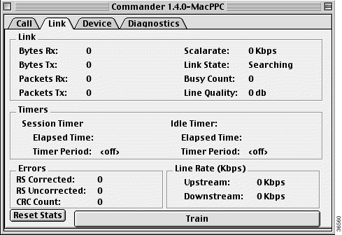
Table 2-4 lists definitions for Link tab fields.
| Field Name | Description |
|---|---|
Number of bytes received. | |
Number of bytes transmitted. | |
Number of packets received. | |
Number of packets transmitted. | |
Your SP sets this rate. ScalaRate only applies to the upstream rate. | |
Link State | Status of the link between the Cisco 67x device and the central office (CO). Options include:
Note When you train at high rates, the Cisco 67x device flashes the Searching, Training, and Pending link states several times before connecting to the CO equipment. |
Number of times the Cisco 67x device attempted to connect to the CO equipment but could not because the CO equipment was busy. | |
Number between 12 and 45. This number describes the quality of the physical connection between the Cisco 67x device and CO equipment. The higher the number, the better the quality of the physical connection. | |
When the timer type is Session, the Cisco 67x device drops the link when Elapsed Time equals the Timer Period. Note Your SP defines the timer types. | |
Idle Timer | When the timer type is Idle, the Cisco 67x device resets the Elapsed Time field when the link resumes activity. However, if the link remains inactive for the entire Timer Period, the Cisco 67x device drops the link. Note Your SP defines the timer types. |
Elapsed time of the timer type. Varies according to Timer Type. If the Timer Type is:
Note If the Elapsed Time field reads Off, it is currently not active. | |
Time period that, after elapsed, cues the Cisco 67x device to drop the link. Varies according to Timer Type. If the Timer Type is:
Note If the Timer Period field reads Off, it is currently not active. | |
Specifies the number of Reed-Solomon Corrected errors. Reed-Solomon is an Error Correction Code (ECC) that allows data that is being read or transmitted to be checked for errors and, if necessary, corrected immediately. | |
Specifies the number of Reed-Solomon uncorrected errors. | |
Cyclic Redundancy Check. Indicates that an error occurred during a transmission. Note It is normal for your system to exhibit a small number of CRC errors. | |
Downstream line rate. | |
Untrain/Train | Untrain (any VCs opened on the Call tab will be closed). |
Use the Device tab to view device information, such as the software type, version number, and other attributes. The Media Access Control (MAC) address field associated with the Cisco 67x device hardware also appears on the Device tab.
The Device tab includes three buttons that allow you to:
 |
Note If a feature does not apply to the platform you have selected, that feature is greyed out and not available. |
Figure 2-9 shows the Device tab as it appears on the PC platform.
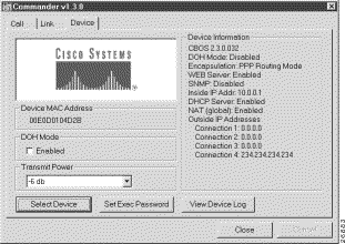
The Device tab contains the following action items:
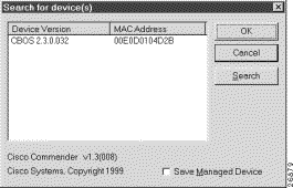
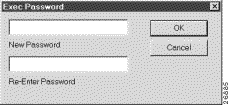
Figure 2-12 shows the Device tab as it appears on a Macintosh platform.
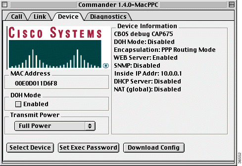
The Device tab contains the following action items:
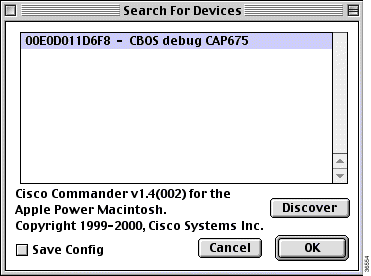
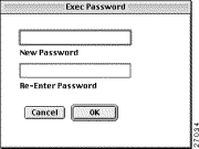
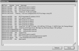
Messages displayed in the Device Log are explained in the Cisco Broadband Operating System (CBOS) user documentation.
 |
Note You must have tftp enabled to download the configuration file.
Otherwise, the following message displays:TFTP daemon is not enabled on device
|
 |
Caution When you click this button, the machine will reboot and you will need to log in again and enter the correct password. |
The Diagnostics tab on a Macintosh platform contains the following action items:

Messages displayed in the Device Log are explained in the Cisco Broadband Operating System (CBOS) user documentation.
Select the configuration file you want to download and click Choose.
 |
Note You must have tftp enabled to download the configuration file.
Otherwise, the following message displays:TFTP daemon is not enabled on device
|

 |
Caution When you download a configuration file, the machine will reboot and you will need to log in again and enter the correct password. |
To exit the dialog box, click Cancel.
![]()
![]()
![]()
![]()
![]()
![]()
![]()
![]()
Posted: Sat Sep 28 01:24:26 PDT 2002
All contents are Copyright © 1992--2002 Cisco Systems, Inc. All rights reserved.
Important Notices and Privacy Statement.