|
|

This chapter describes how to view and change Cisco 605 settings for the PPP and 1483 driver software on Windows NT, Windows 95, and Windows 98 platforms.
The Cisco 605 Commander allows you to view and change settings for each platform. To launch the Cisco 605 Commander, double left-click the Cisco 605 icon in the system tray. The data displayed by the Cisco 605 Commander is automatically updated every two seconds.
This section describes the Commander windows and fields. To display the Cisco 605 commander screens, click one of the tabs:
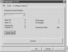
Use the Call page to view the receive and transmit statistics for a connection. Information such as bytes and packets received and transmitted are shown, in addition to the Virtual Path Identifier (VPI)/Virtual Circuit Identifier (VCI) numbers and connection state.
Figure 5-1 shows the Call page.

Table 5-1 lists definitions for the fields in the Cisco 605 Call page.
| Field Name | Description |
|---|---|
Connection number | Connection number. Select a connection number from the drop-down box.
|
Bytes Rx | Number of bytes received for a specified connection. |
Bytes Tx | Number of bytes transmitted for a specified connection. |
Packets Rx | Number of packets received for a specified connection. |
Packets Tx | Number of packets transmitted for a specified connection. |
VPI Number | VPI for a specific connection. The VPI is hard-coded to equal 1. |
VCI Number | VCI for a specific connection. On all platforms using 1483 software, the VCI is hard-coded to equal 1. On all platforms using the PPP software, the VCI number corresponds to the dialed number assigned in Dial-Up Networking (DUN). |
Connection State | Displays the state of the connection. Options include:
|
Reset Stats | Zeroes out all of the counters on this page. |
Use the Link page (Figure 5-2) to view the following information:

Table 5-2 lists definitions for the fields in the Cisco 605 Link page.
| Field Name | Description |
|---|---|
Bytes Rx | Number of bytes received. |
Number of bytes transmitted. | |
Number of packets received. | |
Number of packets transmitted. | |
Scala rate. Your SP sets this rate. Scalarate only applies to the upstream rate. | |
Status of the link between the Cisco 605 and the far-end modem. Options include:
| |
Number of times the Cisco 605 attempted to connect to the far-end equipment but could not because the far-end equipment was busy. | |
Number between 12 and 45. This number describes the quality of the physical connection between the Cisco 605 and far-end equipment. The higher the number, the better the quality of the physical connection. | |
Type of timer. Options include:
| |
Elapsed time of the timer type. Varies according to Timer Type:
| |
Time period that, after elapsed, cues the Cisco 605 to drop the link. Varies according to Timer Type:
| |
Specifies the number of Reed-Solomon Corrected errors. Reed-Solomon is an Error Correction Code (ECC) that allows data that is being read or transmitted to be checked for errors and, when necessary, corrected immediately. | |
Specifies the number of Reed-Solomon uncorrected errors. | |
Cyclic Redundancy Check. Indicates that an error occurred during a transmission. Note It is normal to see a small number of CRC errors. | |
Upstream line rate. You can set this rate on the Settings page of the Cisco 605 Commander, but your SP can override your settings. | |
Downstream line rate. You can set this rate on the Settings page of the Cisco 605 Commander, but your SP can override your settings. | |
Zeroes out all of the counters on this page. |
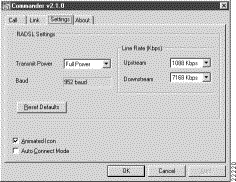
Use the Settings page to view and change RADSL settings. Before changing parameters, shut down any active data connections on the ADSL link. When the Cisco 605 connects with a far-end modem, the fields on the Settings page gray out.
The Cisco 605 now supports dedicated service for the RFC 1483 driver. You have the option to have a dedicated modem at the SP, which provides for uninterrupted ADSL service. You must subscribe to this service by contacting you SP. Once you have subscribed to the service, check the Auto Connect check box on the Settings page to invoke the service.
Figure 5-3 shows the Settings page.

Table 5-3 lists definitions for the fields in the Cisco 605 Settings page.
| Field Name | Description |
|---|---|
Current baud rate | |
Upstream | Allows you to change the current upstream data transfer rate. Note Your SP can override the rate settings. |
Downstream | Allows you to change the current downstream data transfer rate. Note Your SP can override the rate settings. |
Allows you to change the transmit power. Full is the default setting. Note Your SP can override the rate settings. | |
Reset Defaults | Reinstates defaults. |
When checked, causes the Cisco 605 icon to change color when the Cisco 605 is training. | |
Auto Connect Mode | When checked, provides dedicated ADSL service for the 1483 driver. Note This option is grayed out if you are using the PPP driver. |
To apply new parameters, click Apply.
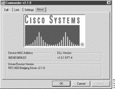
Use the About page to view the software type and version (Figure 5-4) and other attributes

The software type shown is the 1483 driver. If the software type is PPP, the Media Access Control (MAC) address field is grayed out.
![]()
![]()
![]()
![]()
![]()
![]()
![]()
![]()
Posted: Mon Mar 29 08:30:02 PST 1999
Copyright 1989-1999©Cisco Systems Inc.