|
|

This appendix describes how to install and upgrade the dynamic RAM (DRAM) single in-line memory module (SIMM) in Cisco 1400 series routers and includes the following sections:
This section contains safety information that you should read before opening the chassis to upgrade the SIMM.
Read all safety warnings before performing the installation procedure in this document.
 | Warning Only trained and qualified personnel should be allowed to install or replace this equipment. |
 | Warning Before working on a chassis or working near power supplies, unplug the power cord on AC units; disconnect the power at the circuit breaker on DC units. |
 | Warning This equipment is intended to be grounded. Ensure that the host is connected to earth ground during normal use. |
 | Warning Before working on equipment that is connected to power lines, remove jewelry (including rings, necklaces, and watches). Metal objects will heat up when connected to power and ground and can cause serious burns or weld the metal object to the terminals. |
Follow these guidelines when working on equipment powered by electricity:
Electrostatic discharge (ESD) can damage equipment and impair electrical circuitry. It occurs when electronic printed circuit cards are improperly handled. ESD can result in complete or intermittent failures. Always follow ESD-prevention procedures when removing and replacing cards. Ensure that the router chassis is electrically connected to earth ground. Wear an ESD-preventive wrist strap, ensuring that it makes good skin contact. Connect the clip to an unpainted surface of the chassis frame to safely channel unwanted ESD voltages to ground. To properly guard against ESD damage and shocks, the wrist strap and cord must be used correctly. If no wrist strap is available, ground yourself by touching the metal part of the chassis.
 | Caution For safety, periodically check the resistance value of the antistatic strap, which should be between 1 and 10 megohms (Mohm). |
 | Caution Before opening the chassis, be sure that you have discharged all static electricity from your body and the power is OFF. |
Make sure to read the information in the "Safety" section before performing this procedure.
You need the following tools to open the router chassis:
Take the following steps to open the chassis:
Step 1 Turn OFF the power to channel ESD voltages to ground, but do not unplug the power cable.
Step 2 Disconnect any network cables (Ethernet and ATM-25) connected to the router.
Step 3 Turn the unit upside down so that the top section of the chassis is resting on a flat surface and the bottom section is facing up.
Step 4 Use the Phillips screwdriver to remove the single screw located on the bottom of section the chassis, as shown in Step A of Figure B-1.
Step 5 Insert the medium-size flat-blade screwdriver into one of the slots labeled "Pry slot" on the bottom of the router, and twist the blade so that the top and bottom sections of the chassis separate slightly, as shown in Step A of Figure B-1.
Step 6 Repeat Step 5 in the other pry slot.
Step 7 Gently pull the top section away from the bottom section, as shown in Step B of Figure B-1. The fit is snug, so it might be necessary to work the chassis sections apart at each end alternately. Set the cover of the router aside.


Follow the steps in this section to replace the installed SIMM with the new SIMM.
 | Caution Handle the SIMM carefully so it is not damaged during this process. |
Step 1 Attach an ESD-preventive wrist or ankle strap.
Step 2 Locate the installed SIMM on the router motherboard, as shown in the lower right corner of Figure B-2.

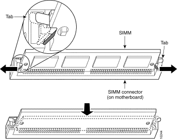
Step 3 Remove the installed SIMM by simultaneously pulling outward on the tabs to unlatch them and raising the SIMM to a vertical position, as shown in Figure B-3.
 | Caution he connector holds the SIMM tightly, so be careful not to break the SIMM connector holders. |

Step 4 Remove the SIMM from the socket.
Step 5 Position the new SIMM so that the polarization notch is at the right end of the SIMM socket.
 | Caution Some SIMMs have the components mounted on the rear side. When you insert the SIMM, use the polarization notch as a reference, not the position of the components on the SIMM. |
Step 6 Insert the new SIMM by sliding the end with the metal fingers into the SIMM socket at a 45-degree angle to the system card. Gently rock the SIMM (front to back) into place until the tabs snap into place. Do not use excessive force because the connector might break.
Step 7 Replace the router cover according to the instructions on the next section, "Closing the Chassis."
Take the following steps to close the chassis:
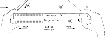
Step 1 Position the top and bottom chassis sections as shown in Figure B-4.

Step 2 Referring to Figure B-4, press the two chassis sections together, and be sure
To fit the two sections together, it might be necessary to work them together at each end alternately; however, use care to prevent bending the chassis edges.
Step 3 When the two sections fit together snugly, slide the chassis top until it fits into the front bezel.
Step 4 Replace the screw that you removed when opening the chassis.
Step 5 Reconnect the network cables.
![]()
![]()
![]()
![]()
![]()
![]()
![]()
![]()
Posted: Fri Sep 27 23:35:33 PDT 2002
All contents are Copyright © 1992--2002 Cisco Systems, Inc. All rights reserved.
Important Notices and Privacy Statement.