|
|

This appendix describes cables and cabling guidelines that should be used with the Cisco 1400 series router and contains the following sections:
The green RJ-45-to-RJ-45 ATM-25 cable connects the Cisco 1401 router through a DSL modem to the ADSL line. This cable must be a Category 3, 4, or 5 unshielded twisted-pair (UTP) cable. The cable that came with your router is Category 5 and is shown in Figure C-1. The signal associated with each pin is described in Table C-1.

| Pin | Signal |
|---|---|
1 | RD+ |
2 | RD- |
3 | Not used |
4 | Not used |
5 | Not used |
6 | Not used |
7 | TD+ |
8 | TD- |
The purple RJ-11-to-RJ-11 ADSL cable connects the Cisco 1407 and Cisco 1417 routers to the ADSL line. This cable must be a Category 3, 4, or 5 unshielded twisted-pair (UTP) cable. The cable that came with your router is Category 5 and is shown in Figure C-2. Cable pinouts are described in Table C-2. Pins 2 and 5 are used for data.

| Pin1 | Pin | |
|---|---|---|
22 | <—> | 2 |
3 | <—> | 3 |
4 | <—> | 4 |
5 | <—> | 5 |
| 1Pins 1 and 6 are not used. 2Pins 2 and 5 are used for data. |
The purple (with a blue stripe) RJ-11-to-RJ-11 POTS crossover cable connects the Cisco 1407 and Cisco 1417 routers to POTS splitters that use pins 3 and 4 for data. (The Cisco 1417 router uses pins 2 and 5 for data.) This cable can be ordered from Cisco. If you provide your own cable, it must be a Category 3, 4, or 5 unshielded twisted-pair (UTP) cable. The orderable Cisco cable is Category 5 and is shown in Figure C-3. Cable pinouts are described in Table C-3.

| Pin1 | Pin | |
|---|---|---|
2 | <—> | 3 |
3 | <—> | 2 |
4 | <—> | 5 |
5 | <—> | 4 |
| 1Pins 1 and 6 are not used. |
An ATM loopback plug is used when performing a loopback test on the Cisco 1401 router. The loopback plug is shown in Figure C-4 and plug pinouts are described in Table C-4.

| Pin1 | Signal | Pin | Signal | |
|---|---|---|---|---|
1 | RD + | < — > | 7 | TD + |
2 | RD - | < — > | 8 | TD - |
| 1Pins 3, 4, 5, and 6 are not used. |
This section describes the yellow RJ-45-to-RJ-45 Ethernet cable used to connect the router to your local Ethernet network. This cable is shipped with the router. The signal associated with each pin is described in Table C-5.
| RJ-45 Pin1 | Signal | Direction | RJ-45 Pin |
|---|---|---|---|
1 | TX+ | —> | 1 |
2 | TX- | —> | 2 |
3 | RX+ | <— | 3 |
6 | RX- | <— | 6 |
| 1Pins 4, 5, 7, and 8 are not used. |
A console cable kit is provided with your router. Use this kit when connecting your router to a PC or terminal.
The console cable kit contains these items:
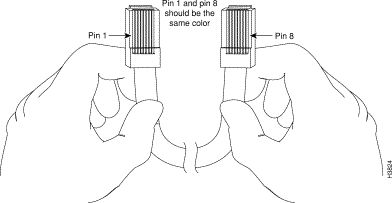
Table C-6 describes the wiring for the console port, the console cable, and both adapters. Figure C-5 illustrates how to identify the console cable, which is also referred to as a rollover cable.
| CONSOLE Port (DTE) | RJ-45-to-RJ-45 Console Cable | Adapter | Adapter | ||
|---|---|---|---|---|---|
| Signal | RJ-45 Pin | RJ-45 Pin | DB-9 Pin | DB-25 Pin | Signal |
- | 1 | 8 | 7 | 4 | - |
DTR | 2 | 7 | 4 | 20 | DSR |
TxD | 3 | 6 | 3 | 2 | RxD |
GND | 4 | 5 | 5 | 7 | GND |
GND | 5 | 4 | 5 | 7 | GND |
RxD | 6 | 3 | 2 | 3 | TxD |
DSR | 7 | 2 | 6 | 6 | DTR |
- | 8 | 1 | 8 | 5 | - |

Table C-7 describes guidelines to follow when creating Ethernet networks. Exact figures might vary depending on the manufacturer of the network equipment.
| Specification | 10BaseT |
|---|---|
Maximum segment length | 100 meters |
Maximum number of segments per network | 5 |
Maximum hop count1 | 4 |
Maximum number of nodes per segment | 1024 |
Cable type supported | UTP |
| 1Hop count = Routing metric used to measure the distance between a source and a destination. |
![]()
![]()
![]()
![]()
![]()
![]()
![]()
![]()
Posted: Fri Sep 27 23:31:56 PDT 2002
All contents are Copyright © 1992--2002 Cisco Systems, Inc. All rights reserved.
Important Notices and Privacy Statement.