|
|

This chapter introduces the Cisco 1400 series router and covers the following topics:
The Cisco 1400 series routers are a family of ATM-25 and ADSL routers that connect small businesses and remote branch offices to the Internet or to larger, corporate networks.
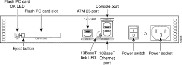
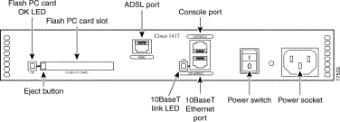
Table 1-1 describes the Cisco 1400 series routers and Figure 1-1 and Figure 1-2 illustrate the router rear panels.
i
| Cisco 1401 | Cisco 1407 | Cisco 1417 |
|---|---|---|
|
|
|


Following are the key features of the Cisco 1400 series routers:
<<Reviewers: Do we need to add more features here for the lastest SW releases?>>
These are some key ADSL elements and terms you should know:
An ADSL line is a DSL that transfers data from the telephone central office to the user much faster than the user sends data to the telephone central office. ADSL is ideal for applications such as high-speed Internet access and video-on-demand, in which the server sends much more data than the client sends. Internet users, in general, download more information from the Internet than they upload.
One of the key features of ADSL is that it operates over existing standard telephone wires, enabling simultaneous voice and data transmissions over the same telephone line.
The Cisco 1400 series routers use ATM over ADSL to transfer data to and from remote networks, such as an ISP or corporate network.
By using ATM, the router can maintain a communication session with the remote location until the session ends. A continuous connection results in a higher quality of service than that of many other data protocols.
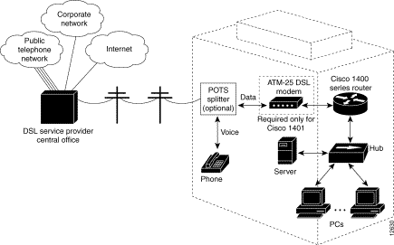
Figure 1-3 illustrates a network that includes a Cisco 1400 series router.
A Cisco 1401 router connects to the ADSL line through a DSL modem. (The Cisco 1407 and Cisco 1417 routers do not require the modem.) Some DSL modems have an integrated POTS splitter, which connects a phone or fax machine to the same ADSL line as the router.
If you are using a telephone and the Cisco 1407 or Cisco 1417 router on the same telphone line, an external POTS splitter is required for optimal performance. A splitter reduces possible interference on both data connections and voice calls, which use different frequencies. For more information, refer to the "Using POTS Splitters and Microfilters" section in the "Installation" chapter later in this guide.

Figure 1-4 and Figure 1-5 illustrate the ports and LEDs on the rear panel of the Cisco 1400 series routers. Table 1-2 describes the rear-panel port functions, and Table 1-3 describes the LEDs.


| Port | Label/Color | Description |
|---|---|---|
Ethernet port | ETHERNET | Connects the router to the local 10BasetT Ethernet network. |
ATM | ATM 25 | Connects the router to the DSL modem. The DSL modem connects the router to the ADSL line. |
ADSL | ADSL | Connects the router directly to an ADSL line or to an ADSL line through a POTS splitter. The POTS splitter enables the router and a telephone to share the ADSL line. |
Console port | CONSOLE | Connects the router to a terminal, terminal server, or PC for software configuration. |
Flash PC card slot | FLASH PC CARD | If not already installed, insert the Flash PC card into this slot. |
Power socket | Input: 100-240 VAC~ | Connects the router to the power supply. |
| LED Label | Color | Description |
|---|---|---|
OK | Green | On means that the Flash memory card is correctly inserted in the Flash PC card slot. |
On means that the router is connected to the Ethernet LAN through the 10BaseT Ethernet port. |
Use the front-panel LEDs to determine network activity and status on the Ethernet port and the WAN port. Figure 1-6 illustrates these LEDs, and Table 1-4 describes them.

| LED Label | Color | Description |
|---|---|---|
| SYSTEM |
|
|
Green | On when DC power is being supplied to the router. | |
OK | Green | On when the router has successfully booted up and the software is functional. This LED blinks during the power-on self-test (POST). |
| ETHERNET |
|
|
Blinks when there is network activity on the Ethernet LAN. | ||
Yellow | Blinks when there are network (packet) collisions on the Ethernet LAN. | |
| WAN |
|
|
On steady when the router has synchronized with the equipment connected to the ATM-25 port (Cisco 1401 router) or the ADSL equipment at the service provider office (Cisco 1407 and Cisco 1417 routers). | ||
ACT | Green | Blinks when data is being sent to or received from the ATM-25 port (Cisco 1401 router) or the ADSL port (Cisco 1407 and Cisco 1417 routers). |
Yellow | On steady when the ATM-25 port (Cisco 1401 router) or the ADSL port (Cisco 1407 and Cisco 1417 routers) is in loopback mode. |
This section describes the types of memory used by the router and how to find out how much of each type the router is using.
The Cisco 1400 series routers have the following types of memory:
Use the show version command to view the amount of NVRAM, DRAM, and Flash memory stored in your router. Below is an example of the show version command. The command output in bold text displays the memory amounts for this router.
1401# show version

Cisco Internetwork Operating System Software
IOS (tm) 1400 Software (C1400-NSY-M),Version 12.0(19980714:220727)
Copyright (c) 1986-1998 by cisco Systems, Inc.
Compiled Wed 15-Jul-98 10:56 by cisco
Image text-base: 0x02005000, data-base: 0x024E9ECC
.
.
.
cisco 1401 (68360) processor (revision A) with 9216K/3072K bytes of
memory.
Processor board ID 04618030, with hardware revision 00000000
Bridging software.
X.25 software, Version 3.0.0.
1 Ethernet/IEEE 802.3 interface(s)
1 ATM network interface(s)
System/IO memory with parity disabled
8192K bytes of DRAM onboard 4096K bytes of DRAM on SIMM

System running from RAM
8K bytes of non-volatile configuration memory.

4096K bytes of processor board PCMCIA flash (Read/Write)


Configuration register is 0x2
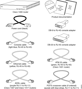
Figure 1-7 shows the items that come in the router accessory kit. Contact your Cisco reseller if anything is missing from your accessory kit.

Table 1-5 is a list of other equipment that you need to completely install your router.
| Equipment | When You Use It |
|---|---|
10BaseT Ethernet hub or 10BaseT Ethernet switch |
You need either a hub or switch, not both, to connect your router to the LAN. |
ATM-DSL modem | An ATM-DSL modem (for example, a Cisco 625 or Cisco 626) connects ATM-based devices (such as the Cisco 1401 router) to ADSL lines. Some DSL modems include an integrated POTS splitter, which connects the router and a telephone or fax machine to the same ADSL line. If you are not sure what type of DSL modem to use with your router, contact your ADSL service provider or your Cisco reseller. |
RJ-11-to-RJ-11 cable | This cable connects a DSL modem (used with the Cisco 1401 router) to the ADSL line. You might need to provide one if it is not included with the modem. |
Optimal router and telephone performance (when the router and telephone are used on the same telephone line) requires a POTS splitter. A splitter reduces interference that might occur on data connections and voice calls. Some types of splitters can be used to connect analog devices, such as a telephone or fax machine, to the same ADSL line as the router. For more information, refer to the "Using POTS Splitters and Microfilters" section in the "Installation" later in this guide. If you are not sure what type of splitter to use, contact your service provider or your Cisco reseller. | |
Microfilters can be used (in addition to a POTS splitter) to further reduce interference on a voice call. Refer to the "Using POTS Splitters and Microfilters" section in the "Installation" later in this guide for detailed information on when to use microfilters with the Cisco 1417 router. If you are not sure what type of microfilter to use, contact your service provider or your Cisco reseller. |
![]()
![]()
![]()
![]()
![]()
![]()
![]()
![]()
Posted: Wed Oct 2 08:49:45 PDT 2002
All contents are Copyright © 1992--2002 Cisco Systems, Inc. All rights reserved.
Important Notices and Privacy Statement.