|
|

This chapter describes the Cisco IAD1101 integrated access device chassis, and the line interface modules supported by the Cisco IAD1101. This chapter includes the following sections:
The Cisco IAD1101 integrated access device provides the following features and technologies for customer premise applications:

Figure 1-2 shows the front panel of the Cisco IAD1101 chassis.

Table 1-1 describes the LEDs on the front panel.
| LED | Status | Condition |
POWER | Green Off | Cisco IAD1101 is on. Cisco IAD1101 is off. |
SYNC | Green Off | Cisco IAD1101 is synchronized with an external timing source. Cisco IAD1101 is not synchronized. |
ACTIVE | Green Off | Cisco IAD1101 is operational or performing a software upgrade. Cisco IAD1101 is powered off or initializing system software. |
Figure 1-3 shows the rear panel of the Cisco IAD1101 chassis.

The rear panel contains the following connectors:
 |
Note The console port does not support a terminal connection. |
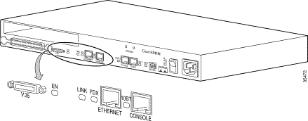
Figure 1-4 shows the connectors and LEDs on the left side of the rear panel, and Table 1-2 describes the LEDs.

| LED | Status | Condition |
EN | Green Yellow Off | V.35 serial DCE cable is connected to the V.35 port. V.35 serial DTE (incorrect) cable is connected to the V.35 port. No cable is connected to the V.35 port. |
LINK | Green Off |
Ethernet port is not active. |
FDX | Green Off | Ethernet port is operating in full-duplex mode. Ethernet port is not operating in full-duplex mode. |
10BT | — | Reserved for future use. |
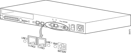
Figure 1-5 shows the connectors and LEDs on the right side of the rear panel, and Table 1-3 describes the LEDs.

| LED | Status | Condition |
LINE 2 | Green Yellow Red Off | T1 line is framed and in service. T1 port is experiencing far end failure. T1 port is experiencing loss of signal (LOS), loss of frame (LOF), or hardware failure. T1 port is out of service |
LINE 1 | Green Yellow Red Off | T1 line is framed and in service. T1 port is experiencing far end failure. T1 port is experiencing loss of signal (LOS), loss of frame (LOF), or hardware failure. T1 port is out of service |
VBAT | Green Off | Battery is supplying power to the Cisco IAD1101. Battery is not connected or not supplying power. |
The Cisco IAD1101 provides 16 FXS circuits with ring generation and line test functionality. These FXS circuits support loop start and ground start operation, with full-time on hook transmission.
For FXS circuit specifications, see the "FXS/16" section.
Line interface modules for the Cisco IAD1101 integrated access device are hot swappable. They can be inserted into (or removed from) the Cisco IAD1101 module slot with or without power applied to the system without incurring damage.
The following line interface modules are available for the Cisco IAD1101:
Each FXS/16 line interface module provides 16 circuits of FXS service.
 |
Note Only 8 POTS/FXS circuits on the FXS/16 module are supported in a Cisco IAD1101 chassis, giving a total of 24 POTS/FXS circuits—16 internal circuits, and 8 on the FXS/16 module. |

The LEDs on the FXS/16 module indicate module status. (See Table 1-4.)
| LED | Status | Condition |
FAIL | Red Off | FXS/16 module has failed. FXS/16 module has not failed. |
BUSY | Green Off | FXS/16 module is in service, and at least one port is in service. FXS/16 module in not in service, or no ports are in service. |
Alternately blinking FAIL and BUSY LEDs indicate that a slot has been provisioned in EMS for another type of module.
Use the 50-pin analog subscriber connector to connect the FXS/16 module. See "Connector and Cable Specifications," for connector information.
![]()
![]()
![]()
![]()
![]()
![]()
![]()
![]()
Posted: Thu Oct 5 17:06:58 PDT 2000
Copyright 1989-2000©Cisco Systems Inc.