|
|

This appendix provides the following cabling and pinout information for the Cisco IAD1101 integrated access device:
 |
Note This appendix specifies pinouts only for the pins used. Pins not listed in the tables in this appendix are not connected. |
Use the yellow Ethernet (straight) cable and RJ-45-to-DB-9 female DTE adapter to connect the console port to the serial port on a Windows NT workstation with EMS and Dial-up Networking installed. Table B-1 lists the pinouts for the asynchronous serial console port, the RJ-45-to-DB-9 female DTE adapter, and the workstation serial port.
 |
Note To configure your Windows NT workstation for Dial-up Networking access to the Cisco IAD1101 through the console port, see the RS-232 Connection application note. |
| Console Port (DTE) | RJ-45 to DB-9 Adapter | Workstation Serial Port | ||
|---|---|---|---|---|
| Signal | Pin Type | RJ-45 Pin | DB-9 Pin | Signal |
No Signal | — | 1 | 9 | RI |
RD_TX_MISC | Output | 2 | 1 | DCD |
DTR | Input | 3 | 4 | DTR |
GND | Ground | 4 | 5 | GND |
TxD | Output | 5 | 2 | RxD |
RxD | Input | 6 | 3 | TxD |
RD_TX_MISC | Output | 7 | 8 | CTS |
No Signal | — | 8 | 7 | RTS |
|
| — | 6 | DSR |
Figure B-1 shows the Ethernet 10BaseT connector (RJ-45) and Table B-2 lists its pinouts.

| Pin | Description |
|---|---|
1 | TX+ |
2 | TX- |
3 | RX+ |
4 | — |
5 | — |
6 | RX- |
7 | — |
8 | — |
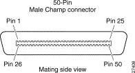
Figure B-2 shows the analog subscriber connector (Amp-Champ) and Table B-3 lists its pinouts.

| Circuit | Pin (Ring) | Pin (Tip) |
|---|---|---|
FXS 1 | 1 | 26 |
FXS 2 | 2 | 27 |
FXS 3 | 3 | 28 |
FXS 4 | 4 | 29 |
FXS 5 | 5 | 30 |
FXS 6 | 6 | 31 |
FXS 7 | 7 | 32 |
FXS 8 | 8 | 33 |
FXS 9 | 9 | 34 |
FXS 10 | 10 | 35 |
FXS 11 | 11 | 36 |
FXS 12 | 12 | 37 |
FXS 13 | 13 | 38 |
FXS 14 | 14 | 39 |
FXS 15 | 15 | 40 |
FXS 16 | 16 | 41 |
Expansion 1 | 17 | 42 |
Expansion 2 | 18 | 43 |
Expansion 3 | 19 | 44 |
Expansion 4 | 20 | 45 |
Expansion 5 | 21 | 46 |
Expansion 6 | 22 | 47 |
Expansion 7 | 23 | 48 |
Expansion 8 | 24 | 49 |
Not Used | 25 | 50 |
Figure B-3 shows the RJ-48 connector wiring for the T1 trunk cable, and Table B-4 lists the pinouts.

| Pin | Description |
|---|---|
1 | RX Tip |
2 | RX Ring |
3 | — |
4 | TX Tip |
5 | TX Ring |
6 | — |
7 | — |
8 | — |
The serial port on the Cisco IAD1101 is a 26-pin connector supporting V.35 DTE connections.
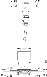
Figure B-4 shows the wiring for the serial to V.35 cable, and Table B-5 lists the DCE pinouts. Arrows indicate signal direction: —> means DTE to DCE and <— means DCE to DTE.

| Serial Connector Pin | Signal Name | Note | Direction | Signal Name | V.35 Pin |
|---|---|---|---|---|---|
J1-22 | MODE_1 | Local connections |
|
|
|
Drain wire |
| Shield | — | Shield_GND | J2-A |
J1-11 | I_CTS/RTS+ | Twisted pair #4 | —> | RTS | J2-C |
J1-08 | O_RTS/CTS+ | Twisted pair #2 | <— | CTS | J2-D |
J1-06 | B_DCD/DCD+ | Twisted pair #1 | —> | RLSD | J2-F |
J1-13 | B_LL/LL+ | Twisted pair #3 | <— | LT | J2-K |
J1-05 | I_RXD/TXD+ | Twisted pair #5 | —> | SD+ | J2-P |
J1-01 | O_TXD/RXD+ | Twisted pair #9 | <— | RD+ | J2-R |
J1-04 | I_RXC/TXCE+ | Twisted pair #6 | —> | SCTE+ | J2-U |
J1-02 | O_TXCE/RXC+ | Twisted pair #8 | <— | SCR+ | J2-V |
J1-03 | B_TXC/TXC+ | Twisted pair #7 | —> | SCT+ | J2-Y |
Figure B-5 shows the wiring for the 26-pin serial DTE to serial DCE cable, and Table B-6 lists the pinouts. Arrows indicate signal direction: —> means DTE to DCE and <— means DCE to DTE.

| DTE Serial Pin | Signal Name | Note | Direction | Signal Name | DCE Serial Pin |
|---|---|---|---|---|---|
J1-22 | MODE_1 | Local connections |
| MODE_1 | J2-22 |
|
| Shield | — |
|
|
J1-08 | O_RTS/CTS+ | Twisted pair #4 | —> | I_CTS/RTS+ | J2-11 |
J1-11 | I_CTS/RTS+ | Twisted pair #2 | <— | O_RTS/CTS+ | J2-08 |
J1-06 | B_DCD/DCD+ | Twisted pair #1 | <— | B_DCD/DCD+ | J2-06 |
J1-13 | B_LL/LL+ | Twisted pair #3 | —> | B_LL/LL+ | J2-13 |
J1-01 | O_TXD/RXD+ | Twisted pair #5 | —> | I_RXD/TXD+ | J2-05 |
J1-05 | I_RXD/TXD+ | Twisted pair #9 | <— | O_TXD/RXD+ | J2-01 |
J1-02 | O_TXCE/RXC+ | Twisted pair #6 | —> | I_RXC/TXCE+ | J2-04 |
J1-04 | I_RXC/TXCE+ | Twisted pair #8 | <— | O_TXCE/RXC+ | J2-02 |
J1-03 | B_TXC/TXC+ | Twisted pair #7 | <— | B_TXC/TXC+ | J2-03 |
![]()
![]()
![]()
![]()
![]()
![]()
![]()
![]()
Posted: Thu Oct 5 17:09:31 PDT 2000
Copyright 1989-2000©Cisco Systems Inc.