|
|

This chapter describes the procedures that operate on the Cisco 6700 embedded software.
The EMS database backup utility allows you to back up the existing configuration of a node to a TFTP server. After the database has been backed up, the node configuration can be restored if needed. The database restore procedure is described in the "Database Erase" section.
Before beginning the embedded software upgrade, complete the following tasks:
To back up the system database:
Step 1 Open the node view of the NE to be backed up.
Step 2 Double-click the node nameplate to launch the NE provisioning window.
Step 3 Select the Database Backup tab from the NE provisioning window. (See Figure 10-1.)
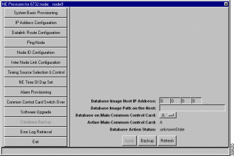
Step 4 Complete the following fields to begin the database backup procedure:
Step 5 Click Apply to save the backup configuration.
Step 6 Click Backup to begin the database backup.
The latest embedded software image is available on Cisco Connection Online (CCO). See the "About This Guide" chapter for more information about CCO.
 | Caution Cisco recommends that you perform a local software upgrade, with a local EMS workstation directly connected to the Cisco 6732 chassis. |
Before beginning the embedded software upgrade:
The Cisco 6732 software upgrade procedure consists of the following sections:
Step 1 Open the node view of the NE to be backed up.
Step 2 From node view, double-click the node nameplate to launch the NE provisioning window.
Step 3 Select Software Upgrade from the function bar to display the software upgrade window.

Step 4 In the Software Image Host IP Address field, enter the IP address of the TFTP server.
Step 5 In the Software Image File Name field, enter SwLoad.fbx.
Step 6 Look at the Active Main Common Control Card field, where EMS indicates the active MCC (A or B).
Step 7 In the Upgrade Software to Main Common Control Card field, select the MCC that is NOT ACTIVE (the standby MCC). For example, if EMS shows that the active MCC is in slot A, select B.
Step 8 Click Apply to confirm the host IP address and path to the image filename.
Step 9 Click Upgrade to download the embedded software image into the Flash memory of the selected MCC.
 | Caution If EMS is unable to complete the embedded software upgrade, an error message will be displayed at the bottom of the NE provision window. In this case, do not reset the MCC; restart the embedded software upgrade process. |
Step 10 The MCC must be reset before the new embedded software becomes active. Use one of the following procedures to reset the MCC:
Step 1 Return to the NE provision window, and click Common Control Card Switch Over in the function bar. (See Figure 10-3.)
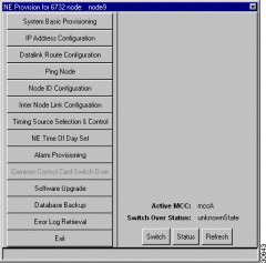
Step 2 Click Switch to switch control from the active MCC to the standby MCC.
Step 1 Select Software Upgrade from the function bar to display the software upgrade window.

Step 2 The Software Image Host IP Address and Software Image File Name fields should already be set from steps 4 and 5; if necessary, enter the correct IP address and file name for the TFTP server.
Step 3 Look at the Active Main Common Control Card field, where EMS indicates the currently active MCC (A or B).
Step 4 In the Upgrade Software to Main Common Control Card field, select the MCC that is NOT ACTIVE. For example, if EMS shows that the active MCC is in slot A, select B.
Step 5 Click Apply to confirm the host IP address and path to the image filename.
Step 6 Click Upgrade to download the embedded software image into the Flash memory of the selected MCC.
 | Caution If EMS is unable to complete the embedded software upgrade, an error message will be displayed at the bottom of the NE provision window. In this case, do not reset the MCC; restart the embedded software upgrade process. |
Step 7 The MCC must be reset before the new embedded software becomes active. Use one of the following procedures to reset the MCC:
 | Caution The following procedure reboots the line cards and effectively takes them out of service. Any traffic being carried on the cards will be dropped. Proper planning and system coordination must be exercised to eliminate or reduce the potential for interrupted subscriber service. |
Step 8 Return to the EMS net view.
Step 9 Right-click the node being upgraded, and select Node Critical Commands from the popup menu. (See Figure 10-5.)
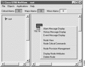
Step 10 Click Line Card Reset in the function bar to open the line card reset window. (See Figure 10-6.)

Step 11 Set the Reset field to Yes.
Step 12 In the Equipped Cards list, highlight all line cards to be reset.
Step 13 Click Apply to reset all selected line cards.
The latest embedded software image is available on Cisco Connection Online (CCO). See the "About This Guide" chapter for more information about CCO.
 | Caution Cisco recommends that you perform a local software upgrade, with a local EMS workstation directly connected to the Cisco 6705 chassis. |
Before beginning the embedded software upgrade, complete the following tasks:
To upgrade or install the embedded software:
Step 1 Open the node view of the NE to be backed up.
Step 2 From node view, double-click the node nameplate to launch the NE provisioning window.
Step 3 Select Software Upgrade from the function bar to display the software upgrade window.

Step 4 In the Software Image Host IP Address field, enter the IP address of the TFTP server.
Step 5 In the Software Image File Name field, enter SwLoad.fbx.
Step 6 The Upgrade Software to Main Common Control Card field should be set to A; the Cisco 6705 has only one MCC, identified as A.
Step 7 Click Apply to confirm the host IP address and path to the image filename.
Step 8 Click Upgrade to download the embedded software image into the Flash memory of the MCC.
 | Caution If EMS is unable to complete the embedded software upgrade, an error message will be displayed in the EMS NE provisioning window. In this case, do not reset the MCC; restart the embedded software upgrade process. |
Step 9 The MCC must be reset before the new embedded software becomes active. Use one of the following procedures to reset the MCC:
 | Caution Resetting the MCC causes all line cards in the Cisco 6705 to be reset as well, momentarily placing the line cards out of service. Any traffic being carried on the line cards will be lost or dropped. Proper planning and system coordination must be exercised to eliminate or reduce the potential for interrupted subscriber service. |
The following embedded software utilities are launched from the node critical commands window:
 | Caution These commands are service-affecting, and any user traffic passing through the node will be dropped. |
To launch the node critical commands window, right-click on a node icon in net view and select Node Critical Commands. (See Figure 10-8.)

You will be prompted to enter a password; contact your EMS administrator to obtain the correct node critical commands password.
Use the database restore function to restore a backed up database to an MCC on the Cisco 6732 or Cisco 6705. See the "Backing Up the System Database" section for the database backup procedure.
The database restore window appears after launching the node critical commands window. (See Figure 10-9.)
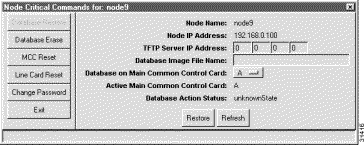
Complete the following fields to provision the database restore function:
Click Restore to upload the database file from the TFTP server to the selected MCC.
The database erase function erases all data stored on an MCC in the Cisco 6732 or Cisco 6705.
 | Caution Erasing the database removes all card and line provisioning, including cross connects and inter-node connections. |
After launching the node critical commands window, click Database Erase in the function bar to open the database erase window. (See Figure 10-10.)
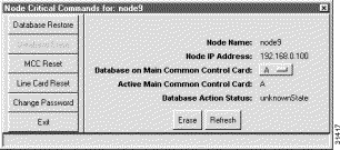
To erase the existing database from an MCC, select the MCC to be erased in the Database on Main Common Control Card field. Click Erase to erase the database.
The MCC reset function resets the MCC and reloads the embedded software.
 | Caution Resetting the MCC causes all line cards in the Cisco 6705 to be reset as well, momentarily placing the line cards out of service. Any traffic being carried on the line cards will be lost or dropped. Proper planning and system coordination must be exercised to eliminate or reduce the potential for interrupted subscriber service. |
From the node critical commands window, click MCC Reset from the function bar to open the MCC reset window. (See Figure 10-11.)
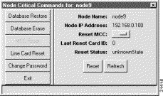
To reset the MCC, select the MCC to be reset (A or B) in the Reset MCC field, and click Reset to reset the selected MCC.
The line card reset function resets all selected cards in the Cisco 6705 or Cisco 6732 chassis.
 | Caution The following procedure reboots the selected line cards and effectively takes them out of service. Any traffic being carried on the cards will be dropped. Proper planning and system coordination must be exercised to eliminate or reduce the potential for interrupted subscriber service. |
From the node critical commands window, click Line Card Reset from the function bar to open the line card reset window. (See Figure 10-12.)

In the Equipped Cards list, highlight all line cards to be reset. Set the Reset field to Yes, and click Apply to reset the selected line cards.
The Change Password function is used to change the node critical commands password. This password is used to launch the node critical commands window.
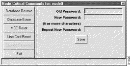
Complete the following fields to change the node critical commands password:
Click Save to change the node critical command password.
![]()
![]()
![]()
![]()
![]()
![]()
![]()
![]()
Posted: Fri Mar 3 15:42:22 PST 2000
Copyright 1989 - 2000©Cisco Systems Inc.