|
|

This chapter describes the procedures to provision the following line cards for ATM services:
Starting from node view, double-click the facility to be provisioned. EMS launches the line provisioning window. (See Figure 9-1.)

The following fields must be set correctly before ATM can be provisioned on the facility:
Close the line provisioning window by clicking the Exit tab. The line can now be provisioned for ATM.
Each line must be provisioned with at least one virtual path (VP) and one virtual channel (VC) before ATM traffic can be accommodated.
Step 1 Starting from node view, right-click the facility to be provisioned, and select ATM Provisioning from the popup menu. EMS launches the ATM provisioning window. (See Figure 9-2.)

Step 2 The following ATM parameters should be set according to the ATM application being used:
Step 3 Click the VP/VC Assignment tab. EMS launches the VP/VC assignment window. (See Figure 9-3.)
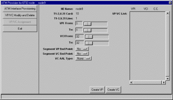
Step 4 Set the following ATM parameters:
Step 5 Click Create VP to provision the VPs, and click Create VC to provision the VCs. The newly created VPs and VCs appear in the VP/VC List at the right side of the window.
To delete VPs and VCs provisioned on a particular line, right-click the line icon in node view, and select ATM Provisioning from the pop-up menu. Click the VP/VC Modify and Delete tab. EMS displays a list of VPs and VCs provisioned on the line. (See Figure 9-4.)

In the VP/VC List at the right side of the window, highlight the VPs and VCs to be deleted. Click Delete to remove the VPs and VCs. EMS removes the deleted VPs and VCs from the list.
After a line had been provisioned with a VP/VC, you can create an ATM cross connect to another line in the NE chassis:
Step 1 To start ATM cross connect provisioning, enter the node view of the node to be provisioned. Move the cursor to the specific line that will be provisioned.
Step 2 Right-click the line and select ATM Cross Connect. EMS creates a list of all available VP/VCs on the line. (See Figure 9-5.)

Step 3 Highlight the VP/VC to be cross connected. EMS displays the VP/VC number in the Selected VPI and Selected VCI windows at the top of the list. (See Figure 9-6.) Click the Selected VCI text box, and drag the cursor to the desired facility.
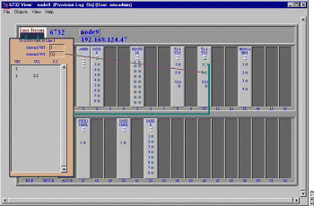
Step 4 After the visual cross connect is drawn, EMS launches the ATM Cross Connect Provisioning window. (See Figure 9-7.) The VP/VC list on the left shows all VP/VCs for the source (originating) line, and the VP/VC list on the right shows VP/VCs for the destination line.
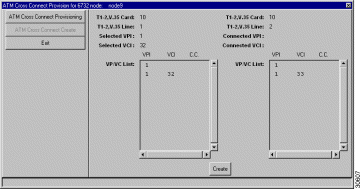
Step 5 Highlight the source VP/VC to be cross connected in the left VP/VC List, then highlight the destination VP/VC in the right VP/VC List. You must select one VP/VC on each line.
Step 6 Click Create to provision the ATM cross connection. Once the cross connection is established, EMS displays the letter y next to the connected VP/VC on each line. (See Figure 9-8.)
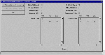
To delete ATM cross connections, right-click on a line in node view, and select ATM Cross Connect from the popup menu. EMS launches the ATM cross connect provisioning window. (See Figure 9-9.) The VP/VC List displays all VP/VCs configured on the line.
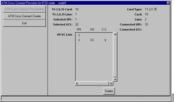
Highlight the VP/VCs to be deleted, then click Delete. EMS removes the deleted cross connections from the VP/VC list display.
To close the ATM cross connect display, right-click on the VPI/VCI list in node view, and select End ATM Cross Connect Display from the popup menu. EMS closes the cross connect display.
![]()
![]()
![]()
![]()
![]()
![]()
![]()
![]()
Posted: Fri Mar 3 15:32:06 PST 2000
Copyright 1989 - 2000©Cisco Systems Inc.