|
|

Table Of Contents
MPLS Label Switch Controller Enhancements
MPLS LSC Functional Description
Controlled ATM Switch Ports Used as Router Interfaces
Using the MPLS LSC as Label Edge Device
Cisco 6400 UAC Operating as an MPLS LSC
Support for ATM Forum Protocols
Tag Switching and MPLS Terminology
Platforms Supported by MPLS LSC
Supported Standards, MIBs, and RFCs
Configuring MPLS on 72xx/75xx Series LSC-Controlled BPX Port
Cisco 6400 UAC LSC Configuration
Verifying MPLS LSC Configuration
Configuring ATM-LSRs with a Cisco 6400 NRP Operating as LSC
Configuring ATM LSRs through ATM Network Using Cisco 7200 LSCs Implementing Virtual Trunking
Configuring ATM LSRs through ATM Network Using Cisco 6400 NRP LSCs Implementing Virtual Trunking
show controllers vsi control-interface
show controllers vsi descriptor
show tag-switching atm-tdp bindings
show tag-switching atm-tdp bindwait
show xtagatm cos-bandwidth-allocation XTagATM
tag-switching atm disable-headend-vc
debug tag-switching xtagatm cross-connect
debug tag-switching xtagatm errors
debug tag-switching xtagatm events
debug tag-switching xtagatm vc
MPLS Label Switch Controller Enhancements
This document describes the Cisco MPLS (multiprotocol label switching) Label Switch Controller (LSC). It describes the MPLS LSC, identifies the platforms supported by the MPLS LSC, provides configuration examples for MPLS LSC components, and describes related IOS command language interpreter (CLI) commands that can be used with the supported platforms.
This document includes the following major sections:
•
Platforms Supported by MPLS LSC
•
Cisco documentation and additional literature are available in a CD-ROM package, which ships with your product. The Documentation CD-ROM, a member of the Cisco Connection Family, is updated monthly. Therefore, it might be more up to date than printed documentation. To order additional copies of the Documentation CD-ROM, contact your local sales representative or call customer service. The CD-ROM package is available as a single package or as an annual subscription. You can also access Cisco documentation on the World Wide Web at http://www.cisco.com, http://www-china.cisco.com, or http://www-europe.cisco.com.
If you are reading Cisco product documentation on the World Wide Web, you can submit comments electronically. Click Feedback in the toolbar, select Documentation, and click Enter the feedback form. After you complete the form, click Submit to send it to Cisco. We appreciate your comments.
Feature Overview
The label switch controller (LSC), combined with the Cisco BPX 8650 IP+ATM switch, supports scalable integration of IP services over an ATM network. The MPLS LSC enables the Cisco BPX 8650 to:
•
•
•
The MPLS LSC supports highly scalable integration of MPLS (IP+ATM) services by using a direct peer relationship between the Cisco BPX 8650 switch and MPLS routers. This direct peer relationship removes the limitation on the number of IP edge routers (typical of traditional IP-over-ATM networks), allowing service providers to meet growing demands for IP services. The MPLS LSC also supports direct and rapid implementation of advanced IP services over ATM networks using Cisco BPX 8650 switches.
MPLS combines the performance and virtual circuit capabilities of Layer 2 (data link layer) switching with the scalability of Layer 3 (network layer) routing capabilities. This combination enables service providers to deliver solutions for managing growth, providing differentiated services, and leveraging existing networking infrastructures.
The MPLS LSC architecture provides the flexibility to:
•
•
By deploying the MPLS LSC across large enterprise networks or wide area networks, customers can:
•
•
•
MPLS LSC Functional Description
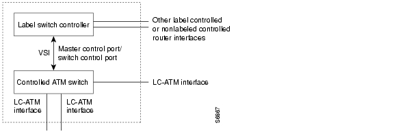
The MPLS LSC is a label switch router (LSR) that is configured to control the operation of a separate ATM switch. Together, the MPLS LSC and the controlled ATM switch function as a single ATM MPLS router (ATM-LSR).
Figure 1 shows the functional relationship between the MPLS LSC and the ATM switch that it controls.
Figure 1 MPLS Label Switch Controller and Controlled ATM Switch
Referring to Figure 1, note that the following devices can function as an MPLS LSC:
•
•
Note also from Figure 1 that a Cisco BPX 8600 Service Node (or a slave ATM device) can function as the controlled ATM switch.
The MPLS LSC controls the ATM switch by means of the Virtual Switch Interface (VSI), which runs over an ATM link connecting the two devices.
The dotted outline in Figure 1 represents the logical boundaries of the external interfaces of the MPLS LSC and the controlled ATM switch, as discovered by the IP routing topology. The controlled ATM switch provides one or more LC-ATM interfaces at this external boundary. The MPLS LSC can incorporate other label controlled or non-label controlled router interfaces.
Controlled ATM Switch Ports Used as Router Interfaces
In the LSC, the LC-ATM ports on the controlled ATM switch are used as an IOS interface type called extended Label ATM (XTagATM). To associate these XTagATM interfaces with particular physical interfaces on the controlled ATM switch, use the interface configuration command extended-port.
Figure 2 shows a typical MPLS LSC configuration which controls three ATM ports on a Cisco BPX switch: ports 6.1, 6.2, and 12.2. These corresponding XTagATM interfaces were created on the MPLS LSC and associated with the corresponding ATM ports on the Cisco BPX switch by means of the extended-port interface configuration command.
Figure 2 Typical MPLS LSC and BPX Configuration
Observe from Figure 2 that:
•
•
Virtual Trunking
Virtual trunks provide connectivity for Cisco WAN MPLS switches through an ATM cloud, as shown in Figure 3. Since several virtual trunks can be configured across a given physical trunk, virtual trunks provide a cost effective means of connecting across an entire ATM network, because each virtual trunk typically consumes only a part of the resources of the physical trunk.
The ATM equipment in the cloud must support virtual path switching and transmission of ATM cells based solely on the VPI in the ATM cell header. The virtual path identifier (VPI) is provided by the ATM cloud administrator (that is, by the Service Provider).
Typical ATM Hybrid Network with Virtual Trunks
Figure 3 shows three Cisco WAN MPLS switching networks, each connected to an ATM network by means of a physical line. The ATM network is shown linking all three of these subnetworks to every other subnetwork with a full meshed network of virtual trunks. In this example, each physical interface is configured with two virtual trunks.
Figure 3 Typical ATM Hybrid Network Using Virtual Trunks
Benefits of Virtual Trunking
Virtual trunks provide the following benefits:
•
•
MPLS Configuration
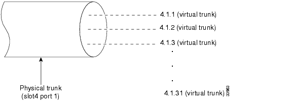
A virtual trunk number (slot number.port number.trunk number) is used to differentiate the virtual trunks found within a physical trunk port. In Figure 4, three virtual trunks 4.1.1, 4.1.2, and 4.1.3 are configured on a physical trunk that connects to the port 4.1 interface of a BXM.
Figure 4 Virtual Trunks Configured on a Physical Trunk
These virtual trunks are mapped to the XtagATM interfaces on the LSC. On the XtagATM interface, you configure the respective VPI value using the command tag-switching atm vp-tunnel vpi. This VPI should match the VPI in the ATM network. The LVCs are generated inside this VP, and this VP carries the LVCs and their traffic across the network.
Virtual Trunk Bandwidth
The total bandwidth of all the virtual trunks on one port cannot exceed the maximum bandwidth of the port. Trunk loading (units of load) is maintained per virtual trunk, but the cumulative loading of all virtual trunks on a port is restricted by the transmit and receive rates for the port.
Virtual Trunk Features
The maximum number of virtual trunks that can be configured per card equals the number of virtual interfaces (VIs) on the BPX. The BXM supports 31 virtual interfaces; hence, it supports up to 31 virtual trunks. Accordingly, you can have interfaces starting from XtagATM411 to XtagATM4131 on the same physical interface.
Using the MPLS LSC as Label Edge Device
As a label edge device, you can use the MPLS LSC to:
•
•
–
–
Note
Cisco 6400 UAC Operating as an MPLS LSC
You can configure the Cisco 6400 UAC to operate as an MPLS LSC in an MPLS network. The hardware that supports MPLS LSC functionality on the Cisco 6400 UAC is described in the following sections.
Cisco 6400 UAC Architectural Overview
A Cisco 6400 UAC that incorporates the following components shown can operate as an MPLS LSC in your network:
•
•
The NRP contains internal ATM interfaces that enable it to be connected to the NSP. However, the NRP cannot directly access the external ATM interfaces of the Cisco 6400 UAC. Access to such external ATM interfaces is provided only by means of the NSP.
Note
•
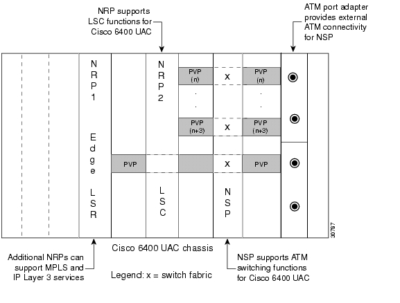
Figure 5 shows the components that you can configure to enable the Cisco 6400 UAC to function as an MPLS LSC.
Figure 5 Cisco 6400 UAC Configured as an MPLS LSC
Configuring PVCs and PVPs in Cisco 6400 UAC NSP Used as an MPLS NRP LSC
The NRP controls the slave ATM switch by means of the Virtual Switch Interface (VSI) protocol. VSI operates over a manually configured PVC that is dedicated to the virtual circuits (VCs) used by the VSI control channel. In order for the NRP LSC to control an ATM switch through the VSI, control VCs need to be cross-connected from the BPX through the NSP to the NRP LSC. The BPX uses defined control VCs for each BXM slot of the BPX chassis, enabling the LSC to control external XTagATM interfaces through the VSI.
Table 1 defines the PVCs that must be configured on the NSP interface connected to the BPX VSI shelf. These PVCs are cross-connected via the NSP to the NRP VSI master control port, which is running the VSI protocol.
For an NRP that is installed in slot 3 of a Cisco 6400 UAC chassis, the master control port would be ATM3/0/0 on the NSP. As shown in Figure 2, the BPX switch control interface is 12.1, and the NSP ATM port connected to this interface is the ATM interface that is cross-connected to ATM3/0/0. Because Figure 2 shows that the BXM slaves in BPX slots 6 and 12 are to be configured as external XTagATM ports, the PVCs that must be cross-connected through the NSP are 0/45 for slot 6 and 0/51 for slot 12, respectively, as outlined in Table 1.
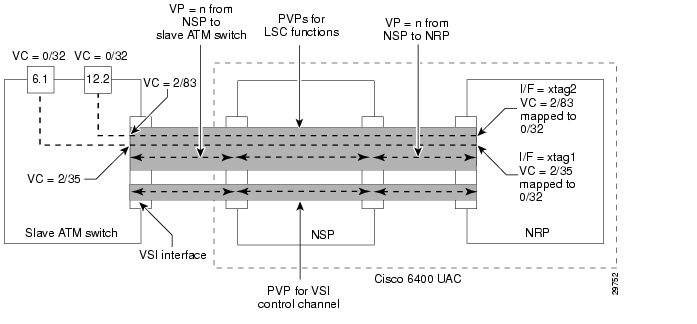
Figure 6 shows the functional relationships among the Cisco 6400 UAC hardware components and the PVPs that you can configure to support MPLS LSC functionality.
Figure 6 Cisco 6400 UAC PVP Configuration for MPLS LSC Functions
All other MPLS LSC functions, such as routing, terminating LVCs, and LDP control VCs (default 0/32), can be accomplished by means of a separate, manually configured PVP (see the upper shaded area in Figure 6). The value of "n" for this manually configured PVP must be the same among all the associated devices (the NRP, the NSP, and the slave ATM switch). Because the NSP uses VP=0 for ATM Forum signaling and the BPX uses VP=1 for autoroute, the value of "n" for this PVP for MPLS LSC functions must be greater than or equal to 2, while not exceeding an upper bound.
Note that some edge LSRs have ATM interfaces with limited VC space per virtual path (VP). For these interface types, several VPs must be defined. For example, the Cisco ATM Port Adapter (PA-A1) and the AIP interface are limited to VC range 33 through 1018. To use the full capacity of the ATM interface, four consecutive VPs must be configured. Furthermore, the selection of these VPs should be within the configured range of the BPX.
For internodal BPX connections, it is suggested that you configure VPs 2 through 15; for edge LSRs, it is suggested that you configure VPs 2 through 5. (See the IOS CLI command "tag-switching atm vpi" on page 74 for examples of how to configure edge LSRs; see the BPX command "cnfrsrc" described in the Cisco BPX 8600 Series documentation for examples of how to configure BPX Service Nodes.)
Control VC Setup for MPLS LSC Functions
After you connect the NRP, the NSP, and the slave ATM switch by means of manually configured PVPs (as shown in Figure 6), the NRP is able to control the slave ATM switch as though it is directly connected to the NRP. The NRP discovers the interfaces of the slave ATM switch and establishes the default control VC to be used in creating MPLS VCs.
The slave ATM switch shown in Figure 6 incorporates two external ATM interfaces (labeled 1 and 2) that are known to the NRP as XTagATM61 and XTagATM122, respectively. On interface 6.1 of the slave ATM switch, VC 0/32 is connected to VC 2/35 by the VSI protocol. On the NRP, VC 2/35 is terminated on interface XTagATM61 and mapped to VC 0/32, also by means of the VSI protocol. This mapping enables the LDP to discover MPLS LSC neighbors by means of the default control VC 0/32 on the physical interface. On interface 12.2 of the slave ATM switch, VC 0/32 is connected to VC 2/83 by the VSI protocol. On the NRP, VC 2/83 is terminated on interface XTagATM122 and mapped to VC 0/32.
Note that the selection of these VCs is dependent on the availability of VC space. Hence it is not predictable what physical VC will be mapped to the external default control VC 0/32 on the XTagATM interface. The control VC will be shown as a PVC on the LSC, as opposed to a LVC, when you execute the IOS CLI command "show xtagatm vc" on page 67.
Basic MPLS LSC Operations
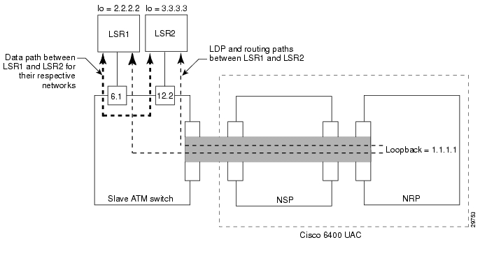
Figure 7 shows a Cisco 6400 UAC containing a single NRP that has been configured to perform basic MPLS LSC operations.
Figure 7 Typical Cisco 6400 UAC Configuration to Support MPLS LSC Functions
Note
Note
ip address 192.103.210.5 255.255.255.255Defining MPLS Control and IP Routing Paths
In the MPLS LSC topology shown in Figure 7, the devices labeled LSR1 and LSR2 are external to the Cisco 6400 UAC. These devices, with loopback addresses as their respective LDP identifiers, are connected to two separate interfaces labeled 6.1 and 12.2 on the slave ATM switch. Both LSR1 and LSR2 learn about each other's routes from the NRP by means of the data path represented as the thick dashed line in Figure 7. Subsequently, LVCs are established by means of LDP operations to create the data paths between LSR1 and LSR2 through the ATM slave switch.
Both LSR1 and LSR2 learn of the loopback address of the NRP and create a data path (LVCs) from each other that terminates in the NRP. These LVCs, called tailend LVCs, are not shown in Figure 7.
Disabling Edge LVCs
By default, the NRP requests LVCs for the next hop devices (the LSRs shown in Figure 7). These LVCs, called headend LVCs, enable the NRP/ATM slave switch combination to operate as an edge label switch router (edge LSR). Because the NRP is dedicated to slave ATM switch control by default, the headend LVCs are not required.
Note
The tag-switching atm disable-headend-vc CLI command disables the default behavior of the NRP in setting up headend switch LVCs, thereby saving VC space over the VP between the NRP and the slave ATM switch that the NRP controls. In the absence of additional LVCs, data traffic follows the same path as that for control traffic.
Support for ATM Forum Protocols
You can connect the MPLS LSC to a network that is running ATM Forum protocols while the MPLS LSC simultaneously performs its functions. However, you must connect the ATM Forum network through a separate ATM interface (that is, not through the master control port).
Tag Switching and MPLS Terminology
Table 2 lists current tag switching terms and the equivalent MPLS terms now being used in this document.
MPLS LSC Benefits
By using the MPLS LSC, you can derive the following benefits:
•
•
•
Platforms Supported by MPLS LSC
You can use the following platforms in conjunction with the MPLS LSC:
•
–
•
–
–
–
Supported Standards, MIBs, and RFCs
•
•
•
Configuration Tasks
This section provides examples of configuration tasks for enabling MPLS LSC functionality.
Refer to the Cisco BPX 8600 Series documentation for BPX Service Node configuration examples.
Configuring MPLS on 72xx/75xx Series LSC-Controlled BPX Port
Note
Note
Cisco 6400 UAC LSC Configuration
Configuring Cisco 6400 UAC NRP as an MPLS LSC
Configuring the Cisco 6400 UAC NSP for MPLS Connectivity to BPX
1. Do not enable tag switching on this interface.
Verifying MPLS LSC Configuration
Configuration Examples
The following sections present typical network configurations for using MPLS LSC functionality.
Configuring ATM-LSRs
The network topology shown in Figure 8 incorporates two ATM-LSRs in an MPLS network. This topology includes two LSCs (Cisco 7200 routers), two BPX service nodes, and two edge LSRs (Cisco 7200 routers).
Figure 8 ATM-LSR Network Configuration Example
Based on Figure 8, the following configuration examples are provided:
•
Configuration for LSC1
7200 LSC1:ip cef!interface loopback0ip address 192.103.210.5 255.255.255.255!interface ATM3/0no ip addresstag-control-protocol vsi!interface XTagATM13extended-port ATM3/0 bpx 1.3ip unnumbered loopback0tag-switching atm vpi 2-15no ip route-cache ceftag-switching ip!interface XTagATM22extended-port ATM3/0 bpx 2.2ip unnumbered loopback0tag-switching atm vpi 2-5no ip route-cache ceftag-switching ipConfiguration for BPX1 and BPX2
BPX1 and BPX2:uptrk 1.1addshelf 1.1 v 1 1cnfrsrc 1.1 256 252207 y 1 e 512 6144 2 15 26000 100000uptrk 1.3cnfrsrc 1.3 256 252207 y 1 e 512 6144 2 15 26000 100000uptrk 2.2cnfrsrc 2.2 256 252207 y 1 e 512 4096 2 5 26000 100000Configuration for LSC2
LSC2:ip cef distributed!interface loopback0ip address 142.2.143.22 255.255.255.255!interface ATM3/0/0no ip addresstag-control-protocol vsi!interface XTagATM13extended-port ATM3/0/0 bpx 1.3ip unnumbered loopback0tag-switching atm vpi 2-15no ip route-cache ceftag-switching ip!interface XTagATM22extended-port ATM3/0/0 bpx 2.2ip unnumbered loopback0tag-switching atm vpi 2-5no ip route-cache ceftag-switching ip!Configuration for Edge LSR1
LSR1:ip cef distributed!interface loopback 0ip address 142.6.132.2 255.255.255.255!interface ATM2/0/0no ip address!interface ATM2/0/0.5 tag-switchingip unnumbered loopback 0tag-switching atm vpi 2-5tag-switching ipConfiguration for Edge LSR2
7200 LSR2:ip cefinterface loopback 0ip address 142.6.142.2 255.255.255.255!interface ATM2/0no ip address!interface ATM2/0.9 tag-switchingip unnumbered loopback 0tag-switching atm vpi 2-5tag-switching ipConfiguring Multi-VCs
When you configure multi-vc support, four label VCs for each destination are created by default. These four VCs are called:
•
•
•
•
This section provides examples for the following configurations, based on the sample network configuration shown earlier in Figure 8:
•
Configuration for LSC1
7200 LSC1:ip cef!interface loopback0ip address 192.103.210.5 255.255.255.255!interface ATM3/0no ip addresstag-control-protocol vsi!interface XTagATM13ip unnumbered loopback 0extended-port ATM3/0 bpx 1.3tag-switching atm vpi 2-15tag-switching atm cos available 25tag-switching atm cos standard 25tag-switching atm cos premium 25tag-switching atm cos control 25tag-switching ip!interface XTagATM23ip unnumbered loopback 0extended-port ATM3/0 bpx 2.2tag-switching atm vpi 2-5tag-switching atm cos available 20tag-switching atm cos standard 30tag-switching atm cos premium 25tag-switching atm cos control 25tag-switching ipConfiguration for BPX1 and BPX2
BPX1 and BPX2:uptrk 1.1addshelf 1.1 v 1 1cnfrsrc 1.1 256 252207 y 1 e 512 6144 2 15 26000 100000uptrk 1.3cnfrsrc 1.3 256 252207 y 1 e 512 6144 2 15 26000 100000uptrk 2.2cnfrsrc 2.2 256 252207 y 1 e 512 4096 2 5 26000 100000Configuration for LSC2
LSC2:ip cef distributed!interface loopback0ip address 142.2.143.22 255.255.255.255!interface ATM3/0/0no ip addresstag-control-protocol vsi!interface XTagATM13ip unnumbered loopback 0extended-port ATM3/0/0 bpx 1.3tag-switching atm vpi 2-15tag-switching atm cos available 25tag-switching atm cos standard 25tag-switching atm cos premium 25tag-switching atm cos control 25tag-switching ip!interface XTagATM23ip unnumbered loopback 0extended-port ATM3/0/0 bpx 2.2tag-switching atm vpi 2-5tag-switching atm cos available 20tag-switching atm cos standard 30tag-switching atm cos premium 25tag-switching atm cos control 25tag-switching ipConfiguration for Edge LSR1
LSR1:ip cef distributedinterface loopback 0ip address 142.6.132.2 255.255.255.255!interface ATM2/0/0no ip address!interface ATM2/0/0.5 tag-switchingip unnumbered loopback 0tag-switching atm vpi 2-5tag-switching atm multi-vctag-switching ipConfiguration for Edge LSR2
7200 LSR2:ip cefinterface loopback 0ip address 142.2.142.2 255.255.255.255!interface ATM2/0no ip address!interface ATM2/0.9 tag-switchingip unnumbered loopback 0tag-switching atm vpi 2-5tag-switching atm multi-vctag-switching ipQoS Support
If LSC1 supports QoS, but LSC2 does not, LSC1 makes VC requests for the following default classes:
•
•
LSC2 ignores the call field in the request and allocates two UBR label VCs.
If LSR1 supports QoS, but LSR2 does not, LSR2 receives the request to create multiple label VCs, but by default, creates class 0 only (UBR).
Configuring ATM-LSRs with a Cisco 6400 NRP Operating as LSC
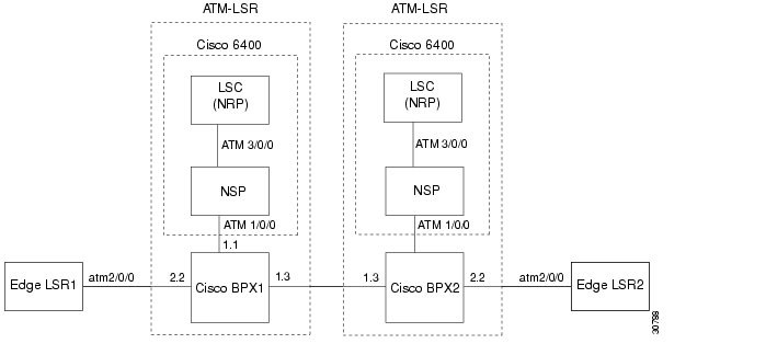
When you use the NRP as an MPLS LSC in the Cisco 6400 UAC, you must configure the NSP to provide connectivity between the NRP and the Cisco BPX switch. When configured in this way (as shown in Figure 9), the NRP is connected to the NSP by means of the internal interface ATM3/0/0, while external connectivity from the Cisco 6400 UAC to the Cisco BPX switch is provided by means of the external interface ATM1/0/0 from the NSP.
Figure 9 Cisco 6400 UAC NRP Operating as an LSC
Based on Figure 9, the following configuration examples are provided:
•
•
•
•
Configuration for 6400 UAC NSP
6400 NSP:!interface ATM3/0/0atm pvp 0 interface ATM1/0/0 0atm pvp 2 interface ATM1/0/0 2atm pvp 3 interface ATM1/0/0 3atm pvp 4 interface ATM1/0/0 4atm pvp 5 interface ATM1/0/0 5atm pvp 6 interface ATM1/0/0 6atm pvp 7 interface ATM1/0/0 7atm pvp 8 interface ATM1/0/0 8atm pvp 9 interface ATM1/0/0 9atm pvp 10 interface ATM1/0/0 10atm pvp 11 interface ATM1/0/0 11atm pvp 12 interface ATM1/0/0 12atm pvp 13 interface ATM1/0/0 13atm pvp 14 interface ATM1/0/0 14atm pvp 15 interface ATM1/0/0 15
Note
atm pvp 0 interface ATM1/0/0 0Configuration for 6400 UAC NRP LSC1
ip cef!interface Loopback0ip address 142.2.143.22 255.255.255.255!interface ATM0/0/0no ip addresstag-control-protocol vsi!interface XTagATM13ip unnumbered Loopback0extended-port ATM0/0/0 bpx 1.3tag-switching atm vpi 2-15tag-switching ip!interface XTagATM22ip unnumbered Loopback0extended-port ATM0/0/0 bpx 2.2tag-switching atm vpi 2-5tag-switching ip!tag-switching atm disable-headend-vcConfiguration for BPX1 and BPX2
BPX1 and BPX2:uptrk 1.1addshelf 1.1 v 1 1cnfrsrc 1.1 256 252207 y 1 e 512 6144 2 15 26000 100000uptrk 1.3cnfrsrc 1.3 256 252207 y 1 e 512 6144 2 15 26000 100000uptrk 2.2cnfrsrc 2.2 256 252207 y 1 e 512 4096 2 5 26000 100000Configuration for 6400 UAC NRP LSC2
ip cef!interface Loopback0ip address 192.103.210.5 255.255.255.255!interface ATM0/0/0no ip addresstag-con trol-protocol vsi!interface XTagATM13ip unnumbered Loopback0extended-port ATM0/0/0 bpx 1.3tag-switching atm vpi 2-15tag-switching ip!interface XTagATM22ip unnumbered Loopback0extended-port ATM0/0/0 bpx 2.2tag-switching atm vpi 2-5tag-switching ip!tag-switching atm disable-headend-vcConfiguration for Edge LSR1
LSR1:ip cef distributed!interface loopback 0ip address 142.6.132.2 255.255.255.255!interface ATM2/0/0no ip address!interface ATM2/0/0.5 tag-switchingip unnumbered loopback 0tag-switching atm vpi 2-5tag-switching ipConfiguration for Edge LSR2
LSR2:ip cef distributed!interface loopback 0ip address 142.6.142.2 255.255.255.255!interface ATM2/0/0no ip address!interface ATM2/0/0.9 tag-switchingunnumbered loopback 0tag-switching atm vpi 2-5tag-switching ipConfiguring ATM LSRs through ATM Network Using Cisco 7200 LSCs Implementing Virtual Trunking
The network topology shown in Figure 10 incorporates two ATM-LSRs using virtual trunking to create an MPLS network through a private ATM Network. This topology includes two LSCs (Cisco 7200 routers), two BPX Service Nodes, and two edge LSRs (Cisco 7200 routers).
Figure 10 ATM-LSR Virtual Trunking through ATM Network
Based on Figure 10, the following configuration examples are provided:
•
•
•
Configuration for LSC1 Implementing Virtual Trunking
7200 LSC1:ip cef!interface loopback0ip address 192.103.210.5 255.255.255.255!interface ATM3/0no ip addresstag-control-protocol vsi!interface XTagATM132extended-port ATM3/0 bpx 1.3.2ip unnumbered loopback0tag-switching atm vp-tunnel 2no ip route-cache ceftag-switching ip!interface XTagATM22extended-port ATM3/0 bpx 2.2ip unnumbered loopback0tag-switching atm vpi 2-5no ip route-cache ceftag-switching ipConfiguration for BPX1 and BPX2
BPX1 and BPX2:uptrk 1.1addshelf 1.1 v 1 1cnfrsrc 1.1 256 252207 y 1 e 512 6144 2 15 26000 100000uptrk 1.3.2cnftrk 1.3.2 100000 N 1000 7F V,TS,NTS,FR,FST,CBR,NRT-VBR,ABR,RT-VBR N TERRESTRIAL 10 0 N N Y Y Y CBR 2cnfrsrc 1.3.2 256 252207 y 1 e 512 6144 2 2 26000 100000uptrk 2.2cnfrsrc 2.2 256 252207 y 1 e 512 4096 2 5 26000 100000Configuration for LSC2 Implementing Virtual Trunking
LSC2:ip cef distributed!interface loopback0ip address 142.2.143.22 255.255.255.255!interface ATM3/0/0no ip addresstag-control-protocol vsi!interface XTagATM132extended-port ATM3/0/0 bpx 1.3.2ip unnumbered loopback0tag-switching atm vp-tunnel 2no ip route-cache ceftag-switching ip!interface XTagATM22extended-port ATM3/0/0 bpx 2.2ip unnumbered loopback0tag-switching atm vpi 2-5no ip route-cache ceftag-switching ipConfiguration for Edge LSR1
LSR1:ip cef distributedinterface loopback 0ip address 142.6.132.2 255.255.255.255!interface ATM2/0/0no ip address!interface ATM2/0/0.5 tag-switchingip unnumbered loopback 0tag-switching atm vpi 2-5tag-switching ipConfiguration for Edge LSR2
7200 LSR2:ip cefinterface loopback 0ip address 142.6.142.2 255.255.255.255!interface ATM2/0no ip address!interface ATM2/0.9 tag-switchingip unnumbered loopback 0tag-switching atm vpi 2-5tag-switching ipConfiguring ATM LSRs through ATM Network Using Cisco 6400 NRP LSCs Implementing Virtual Trunking
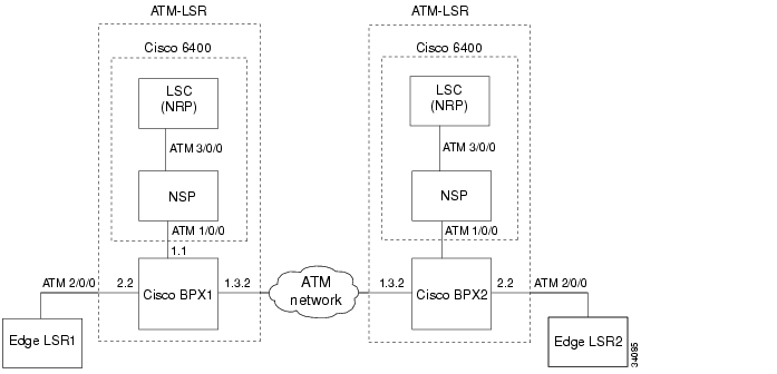
The network topology shown in Figure 11 incorporates two ATM-LSRs using virtual trunking to create an MPLS network through a private ATM Network. This topology includes two LSCs (Cisco 6400 UAC NRP routers), two BPX Service Nodes, and two edge LSRs (7200 routers).
Figure 11 Cisco 6400 NRP Operating as LSC Implementing Virtual Trunking
Based on Figure 11, the following configuration examples are provided:
•
•
•
•
Configuration for 6400 UAC NSP
6400 NSP:!interface ATM3/0/0atm pvp 0 interface ATM1/0/0 0atm pvp 2 interface ATM1/0/0 2atm pvp 3 interface ATM1/0/0 3atm pvp 4 interface ATM1/0/0 4atm pvp 5 interface ATM1/0/0 5atm pvp 6 interface ATM1/0/0 6atm pvp 7 interface ATM1/0/0 7atm pvp 8 interface ATM1/0/0 8atm pvp 9 interface ATM1/0/0 9atm pvp 10 interface ATM1/0/0 10atm pvp 11 interface ATM1/0/0 11atm pvp 12 interface ATM1/0/0 12atm pvp 13 interface ATM1/0/0 13atm pvp 14 interface ATM1/0/0 14atm pvp 15 interface ATM1/0/0 15
Note
atm pvp 0 interface ATM1/0/0 0Configuration for 6400 UAC NRP LSC1 Implementing Virtual Trunking
ip cef!interface Loopback0ip address 142.2.143.22 255.255.255.255!interface ATM0/0/0no ip addresstag-control-protocol vsi!interface XTagATM132ip unnumbered Loopback0extended-port ATM0/0/0 bpx 1.3.2tag-switching atm vp-tunnel 2tag-switching ip!interface XTagATM22ip unnumbered Loopback0extended-port ATM0/0/0 bpx 2.2tag-switching atm vpi 2-5tag-switching ip!tag-switching atm disable-headend-vcConfiguration for BPX1 and BPX2
BPX1 and BPX2:uptrk 1.1addshelf 1.1 v 1 1cnfrsrc 1.1 256 252207 y 1 e 512 6144 2 15 26000 100000uptrk 1.3.2cnftrk 1.3.2 100000 N 1000 7F V,TS,NTS,FR,FST,CBR,NRT-VBR,ABR,RT-VBR N TERRESTRIAL 10 0 N N Y Y Y CBR 2cnfrsrc 1.3.2 256 252207 y 1 e 512 6144 2 2 26000 100000uptrk 2.2cnfrsrc 2.2 256 252207 y 1 e 512 4096 2 5 26000 100000Configuration for 6400 UAC NRP LSC2 Implementing Virtual Trunking
ip cef!interface Loopback0ip address 192.103.210.5 255.255.255.255!interface ATM0/0/0no ip addresstag-con trol-protocol vsi!interface XTagATM132ip unnumbered Loopback0extended-port ATM0/0/0 bpx 1.3.2tag-switching atm vp-tunnel 2tag-switching ip!interface XTagATM22ip unnumbered Loopback0extended-port ATM0/0/0 bpx 2.2tag-switching atm vpi 2-5tag-switching ip!tag-switching atm disable-headend-vcConfiguration for Edge LSR1
LSR1:ip cef distributed!interface loopback 0ip address 142.6.132.2 255.255.255.255!interface ATM2/0/0no ip address!interface ATM2/0/0.5 tag-switchingip unnumbered loopback 0tag-switching atm vpi 2-5tag-switching ipConfiguration for Edge LSR2
LSR2:ip cef distributed!interface loopback 0ip address 142.6.142.2 255.255.255.255!interface ATM2/0/0no ip address!interface ATM2/0/0.9 tag-switchingunnumbered loopback 0tag-switching atm vpi 2-5tag-switching ipCommand Reference
This section describes the CLI commands that you can use in conjunction with the MPLS LSC:
•
•
•
•
•
•
•
•
•
All other commands used with this feature are documented in the Cisco IOS Release 12.0 command reference publications.
Cisco IOS Release 12.0(1)T or later enables you to search and filter the output for the show and more commands. This capability helps you to sort through large amounts of output, or to exclude output that you do not need.
To use this functionality, enter a show or more command, followed by the "pipe" character (|), one of the keywords begin, include, or exclude, and an expression that you want to search or filter on:
command | {begin | include | exclude} regular-expression
An example of a show atm vc command follows, which indicates that you want the command output to begin with the first line containing the "PeakRate" expression:
show atm vc | begin PeakRate
For more information about the search and filter capability, refer to the Cisco IOS Release 12.0(1)T feature module entitled CLI String Search.
Command Conventions
extended-port
To associate the currently selected extended MPLS ATM (XTagATM) interface with a particular external interface on the remotely controlled ATM switch, use the following interface configuration command.
extended-port ctrl-if {bpx bpx-port-number | descriptor vsi-descriptor | vsi vsi-port-number }
Syntax Description
Defaults
No default behavior or values.
Command Modes
Interface configuration
Command History
Usage Guidelines
The extended-port interface configuration command associates an XTagATM interface with a particular external interface on the remotely controlled ATM switch. The three alternate forms of the command permit the external interface on the controlled ATM switch to be specified in three different ways.
Examples
The following example shows you how to create an extended MPLS ATM interface and bind it to BPX port 2.3.
interface XTagATM0extended-port atm0/0 bpx 2.3Related Commands
interface XTagATM
Enters interface configuration mode for an extended MPLS ATM (XTagATM) interface.
interface XTagATM
To enter interface configuration mode for the extended MPLS ATM (XTagATM) interface, use the following interface XTagATM global configuration command. The interface is created the first time this command is issued for a particular interface number.
interface XTagATM if-num
Syntax Description
Defaults
No default behavior or values.
Command Modes
Global configuration
Command History
Usage Guidelines
Extended MPLS ATM interfaces are virtual interfaces that are created on first reference-like tunnel interfaces. Extended MPLS ATM interfaces are similar to ATM interfaces except that the former only supports LC-ATM encapsulation.
Examples
The following example shows how you create an extended MPLS ATM interface with interface number 62:
(config)# interface XTagATM62Related Commands
extended-port
Associates the currently selected extended MPLS ATM (XTagATM) interface with a remotely controlled switch.
show atm vc
To display information about private ATM virtual circuits (VCs), use the following show atm vc privileged EXEC command.
show atm vc [vcd]
Private VCs exist on the control interface of an MPLS LSC to support corresponding VCs on an extended MPLS ATM interface.
Syntax Description
Defaults
No default behavior or values.
Command Modes
EXEC
Command History
Usage Guidelines
VCs on the extended MPLS ATM interfaces do not appear in the show atm vc command output. Instead, the show xtagatm vc command provides similar output which shows information only on extended MPLS ATM VCs.
Examples
In the following example, no VCD is specified and private VCs are present.
Router# show atm vcAAL / Peak Avg. BurstInterface VCD VPI VCI Type Encapsulation Kbps Kbps Cells StatusATM1/0 1 0 40 PVC AAL5-SNAP 0 0 0 ACTIVEATM1/0 2 0 41 PVC AAL5-SNAP 0 0 0 ACTIVEATM1/0 3 0 42 PVC AAL5-SNAP 0 0 0 ACTIVEATM1/0 4 0 43 PVC AAL5-SNAP 0 0 0 ACTIVEATM1/0 5 0 44 PVC AAL5-SNAP 0 0 0 ACTIVEATM1/0 15 1 32 PVC AAL5-XTAGATM 0 0 0 ACTIVEATM1/0 17 1 34 TVC AAL5-XTAGATM 0 0 0 ACTIVEATM1/0 26 1 43 TVC AAL5-XTAGATM 0 0 0 ACTIVEATM1/0 28 1 45 TVC AAL5-XTAGATM 0 0 0 ACTIVEATM1/0 29 1 46 TVC AAL5-XTAGATM 0 0 0 ACTIVEATM1/0 33 1 50 TVC AAL5-XTAGATM 0 0 0 ACTIVEWhen you specify a VCD value and the VCD corresponds to that of a private VC on a control interface, the display output appears as follows:
Router# show atm vc 15ATM1/0 33 1 50 TVC AAL5-XTAGATM 0 0 0 ACTIVE ATM1/0: VCD: 15, VPI: 1, VCI: 32, etype:0x8, AAL5 - XTAGATM, Flags: 0xD38PeakRate: 0, Average Rate: 0, Burst Cells: 0, VCmode: 0x0 XTagATM1, VCD: 1, VPI: 0, VCI: 32 OAM DISABLED, InARP DISABLED InPkts: 38811, OutPkts: 38813, InBytes: 2911240, OutBytes: 2968834 InPRoc: 0, OutPRoc: 0, Broadcasts: 0 InFast: 0, OutFast: 0, InAS: 0, OutAS: 0 OAM F5 cells sent: 0, OAM cells received: 0 Status: ACTIVETable 3 describes the significant fields in the sample command output shown above.
show interface XTagATM
To display information about an extended MPLS ATM interface, use the following show interface XTagATM EXEC command.
show interface XTagATM if-num
Syntax Description
Defaults
No default behavior or values.
Command Modes
EXEC
Command History
Usage Guidelines
Extended MPLS ATM interfaces are virtual interfaces that are created on first reference like tunnel interfaces. Extended MPLS ATM interfaces are similar to ATM interfaces except that the former only supports LC-ATM encapsulation.
Examples
The following is sample output from the show interface XTagATM command:
Router# show interface XTagATM0XTagATM0 is up, line protocol is upHardware is Tag-Controlled Switch PortInterface is unnumbered. Using address of Loopback0 (12.0.0.17)MTU 4470 bytes, BW 156250 Kbit, DLY 80 usec, rely 255/255, load 1/255Encapsulation ATM Tagswitching, loopback not setEncapsulation(s): AAL5Control interface: ATM1/0, switch port: bpx 10.29 terminating VCs, 16 switch cross-connectsSwitch port traffic:129302 cells input, 127559 cells outputLast input 00:00:04, output never, output hang neverLast clearing of "show interface" counters neverQueueing strategy: fifoOutput queue 0/0, 0 drops; input queue 0/75, 0 dropsTerminating traffic:5 minute input rate 1000 bits/sec, 1 packets/sec5 minute output rate 0 bits/sec, 1 packets/sec61643 packets input, 4571695 bytes, 0 no bufferReceived 0 broadcasts, 0 runts, 0 giants0 input errors, 0 CRC, 0 frame, 0 overrun, 0 ignored, 0 abort53799 packets output, 4079127 bytes, 0 underruns0 output errors, 0 collisions, 0 interface resets0 output buffers copied, 0 interrupts, 0 failuresTable 4 describes the significant fields in the sample command output shown above.
Related Commands
interface XTagATM
Enters configuration mode for an extended MPLS ATM (XTagATM) interface.
show controllers XTagATM
To display information about an extended MPLS ATM interface controlled through the VSI protocol (or, if an interface is not specified, to display information about all extended MPLS ATM interfaces controlled through the VSI protocol), use the following show controllers XTagATM EXEC command.
show controllers XTagATM if-num
Syntax Description
Defaults
No default behavior or values.
Command Modes
EXEC
Command History
Usage Guidelines
Per-interface information includes the following:
•
•
•
•
•
•
•
•
Similar information appears if you enter the show controllers vsi descriptor command. However, you must specify an interface by its (switch-supplied) physical descriptor, instead of its IOS interface name. For the Cisco BPX switch, the physical descriptor has the form:
slot.port.0
Examples
In this example, the sample output is from the show controllers XTagATM command specifying interface 0.
Router# show controllers XTagATM 0Interface XTagATM0 is up Hardware is Tag-Controlled ATM Port (on BPX switch BPX-VSI1) Control interface ATM1/0 is up Physical descriptor is 10.2.0 Logical interface 0x000A0200 (0.10.2.0) Oper state ACTIVE, admin state UP VPI range 1-255, VCI range 32-65535 VPI is not translated at end of link Tag control VC need not be strictly in VPI/VCI range Available channels: ingress 30, egress 30 Maximum cell rate: ingress 300000, egress 300000 Available cell rate: ingress 300000, egress 300000 Endpoints in use: ingress 7, egress 8, ingress/egress 1 Rx cells 134747 rx cells discarded 0, rx header errors 0 rx invalid addresses (per card): 52994 last invalid address 0/32 Tx cells 132564 tx cells discarded: 0Table 5 describes the significant fields in the sample command output shown above.
Related Commands
show controllers vsi descriptor
Displays information about a switch interface discovered by the MPLS LSC through the VSI.
show controllers vsi control-interface
To display information about an ATM interface configured with the tag-control-protocol vsi EXEC command to control an external switch (or if an interface is not specified, to display information about all VSI control interfaces), use the following show controllers vsi control-interface command.
show controllers vsi control-interface [interface]
Syntax Description
Defaults
No default behavior or values.
Command Modes
EXEC
Command History
Examples
The following is sample output from the show controllers vsi control-interface command:
Router# show controllers vsi control-interfaceInterface: ATM2/0 Connections: 14The display shows the number of cross-connects currently on the switch that were established by the MPLS LSC through the VSI over the control interface.
Related Commands
show controllers vsi descriptor
To display information about a switch interface discovered by the MPLS LSC through VSI, or if no descriptor is specified, about all such discovered interfaces, use the following show controllers vsi descriptor EXEC command. You specify an interface by its (switch-supplied) physical descriptor.
show controllers vsi descriptor [descriptor]
Syntax Description
descriptor
(Optional). Physical descriptor. For the Cisco BPX switch, the physical descriptor has the following form: slot.port.0
Defaults
No default behavior or values.
Command Modes
EXEC
Command History
Usage Guidelines
Per-interface information includes the following:
•
•
•
•
•
•
•
•
Similar information is displayed when you enter the show controllers XTagATM command. However, you must specify an IOS interface name instead of a physical descriptor.
Examples
The following is sample output from the show controllers vsi descriptor command:
Router# show controllers vsi descriptor 12.2.0Phys desc: 12.2.0Log intf: 0x000C0200 (0.12.2.0)Interface: XTagATM0IF status: up IFC state: ACTIVE Min VPI: 1 Maximum cell rate: 10000 Max VPI: 259 Available channels: 2000 Min VCI: 32 Available cell rate (forward): 10000 Max VCI: 65535 Available cell rate (backward): 10000Table 6 describes the significant fields in the sample command output shown above.
Related Commands
show controllers XTagATM
Displays information about an extended MPLS ATM interface.
show controllers vsi session
To display information about all sessions with VSI slaves, use the following show controllers vsi session EXEC command.
show controllers vsi session [session-num [interface interface]]
Note
Syntax Description
Defaults
No default behavior or values.
Command Modes
EXEC
Command History
Usage Guidelines
If a session number and an interface are specified, detailed information on the individual session is presented. If the session number is specified, but the interface is omitted, detailed information on all sessions with that number is presented. (Only one session can contain a given number in the first release, since multiple control interfaces are not supported.)
Examples
The following is sample output from the show controllers vsi session command:
Router# show controllers vsi sessionInterface Session VCD VPI/VCI Switch/Slave Ids Session StateATM0/0 0 1 0/40 0/1 ESTABLISHED ATM0/0 1 2 0/41 0/2 ESTABLISHED ATM0/0 2 3 0/42 0/3 DISCOVERY ATM0/0 3 4 0/43 0/4 RESYNC-STARTING ATM0/0 4 5 0/44 0/5 RESYNC-STOPPING ATM0/0 5 6 0/45 0/6 RESYNC-UNDERWAY ATM0/0 6 7 0/46 0/7 UNKNOWN ATM0/0 7 8 0/47 0/8 UNKNOWN ATM0/0 8 9 0/48 0/9 CLOSING ATM0/0 9 10 0/49 0/10 ESTABLISHED ATM0/0 10 11 0/50 0/11 ESTABLISHED ATM0/0 11 12 0/51 0/12 ESTABLISHEDTable 7 describes the significant fields in the sample command output shown above.
In the following example, session number 9 is specified with the show controllers vsi session command:
Router# show controllers vsi session 9Interface: ATM1/0 Session number: 9VCD: 10 VPI/VCI: 0/49Switch type: BPX Switch id: 0Controller id: 1 Slave id: 10Keepalive timer: 15 Powerup session id: 0x0000000ACfg/act retry timer: 8/8 Active session id: 0x0000000AMax retries: 10 Ctrl port log intf: 0x000A0100Trap window: 50 Max/actual cmd wndw: 21/21Trap filter: all Max checksums: 19Current VSI version: 1 Min/max VSI version: 1/1Messages sent: 2502 Inter-slave timer: 4.000Messages received: 2502 Messages outstanding: 0Table 8 describes the significant fields in the sample command output shown above.
Related Commands
show controllers vsi status
To display a one-line summary of each VSI-controlled interface, use the following show controllers vsi status EXEC command.
show controllers vsi status
Syntax Description
This command has no arguments or keywords.
Defaults
No default behavior or values.
Related Commands
EXEC
Command History
Usage Guidelines
If an interface has been discovered by the LSC, but no extended MPLS ATM interface has been associated with it through the extended-port interface configuration command, then the interface name is marked <unknown>, and interface status is marked n/a.
Examples
The following is sample output from the show controllers vsi status command:
Router# show controllers vsi statusInterface Name IF Status IFC State Physical Descriptor switch control port n/a ACTIVE 12.1.0 XTagATM0 up ACTIVE 12.2.0 XTagATM1 up ACTIVE 12.3.0 <unknown> n/a FAILED-EXT 12.4.0Table 9 describes the significant fields in the sample command output shown above.
show controllers vsi traffic
To display traffic information about VSI-controlled interfaces, VSI sessions, or VCs on VSI-controlled interfaces, use the following show controllers vsi traffic EXEC command.
show controllers vsi traffic [{ descriptor descriptor | session session-num |vc [descriptor descriptor [vpi vci ]]}]
Syntax Description
descriptor descriptor
Specifies the interface.
session session-num
Specifies a session number.
vpi
Virtual path identifier.
vci
Virtual circuit identifier.
Defaults
No default behavior or values.
Command Modes
EXEC
Command History
Usage Guidelines
If none of the optional command parameters is specified, traffic for all interfaces is displayed. You can specify a single interface by its (switch-supplied) physical descriptor. For the BPX, the physical descriptor has the form:
slot.port. 0
If a session number is specified, VSI protocol traffic counts by message type are displayed. The VC traffic display is the same as the one produced by the show xtagatm vc cross-connect traffic descriptor command.
Examples
The following is sample output from the show controllers vsi traffic command:
Router# show controllers vsi trafficPhys desc: 10.1.0Interface: switch control portIF status: n/aRx cells: 304250 Rx cells discarded: 0Tx cells: 361186 Tx cells discarded: 0Rx header errors: 4294967254 Rx invalid addresses (per card): 80360Last invalid address: 0/53Phys desc: 10.2.0Interface: XTagATM0IF status: upRx cells: 202637 Rx cells discarded: 0Tx cells: 194979 Tx cells discarded: 0Rx header errors: 4294967258 Rx invalid addresses (per card): 80385Last invalid address: 0/32Phys desc: 10.3.0Interface: XTagATM1IF status: upRx cells: 182295 Rx cells discarded: 0Tx cells: 136369 Tx cells discarded: 0Rx header errors: 4294967262 Rx invalid addresses (per card): 80372Last invalid address: 0/32Table 10 describes the significant fields in the sample command output shown above.
The following sample output is displayed when you enter the show controllers vsi traffic session 9 command:
Router# show controllers vsi traffic session 9Sent ReceivedSw Get Cnfg Cmd: 3656 Sw Get Cnfg Rsp: 3656Sw Cnfg Trap Rsp: 0 Sw Cnfg Trap: 0Sw Set Cnfg Cmd: 1 Sw Set Cnfg Rsp: 1Sw Start Resync Cmd: 1 Sw Start Resync Rsp: 1Sw End Resync Cmd: 1 Sw End Resync Rsp: 1Ifc Getmore Cnfg Cmd: 1 Ifc Getmore Cnfg Rsp: 1Ifc Cnfg Trap Rsp: 4 Ifc Cnfg Trap: 4Ifc Get Stats Cmd: 8 Ifc Get Stats Rsp: 8Conn Cmt Cmd: 73 Conn Cmt Rsp: 73Conn Del Cmd: 50 Conn Del Rsp: 0Conn Get Stats Cmd: 0 Conn Get Stats Rsp: 0Conn Cnfg Trap Rsp: 0 Conn Cnfg Trap: 0Conn Bulk Clr Stats Cmd: 0 Conn Bulk Clr Stats Rsp: 0Gen Err Rsp: 0 Gen Err Rsp: 0unused: 0 unused: 0unknown: 0 unknown: 0TOTAL: 3795 TOTAL: 3795Table 11 describes the significant fields in the sample command output shown above.
show tag-switching atm-tdp bindings
To display the requested entries from the ATM LDP label bindings database, use the following show tag-switching atm-tdp bindings EXEC command.
show tag-switching atm-tdp bindings [A.B.C.D {mask | length}]
[local-tag | remote-tag vpi vci] [neighbor atm slot/subslot/port]
[remote-tag vpi vci]Syntax Description
Defaults
Displays all database entries.
Command Modes
EXEC
Command History
Usage Guidelines
The display output can show the entire database or a subset of entries based on the prefix, the VC label value, or an assigning interface.
Examples
The following is sample output from this command.
Switch# show tag-switching atm-tdp bindingsDestination: 13.13.13.6/32Headend Router ATM1/0.1 (2 hops) 1/33 Active, VCD=8, CoS=availableHeadend Router ATM1/0.1 (2 hops) 1/34 Active, VCD=9, CoS=standardHeadend Router ATM1/0.1 (2 hops) 1/35 Active, VCD=10, CoS=premiumHeadend Router ATM1/0.1 (2 hops) 1/36 Active, VCD=11, CoS=controlDestination: 102.0.0.0/8Headend Router ATM1/0.1 (1 hop) 1/37 Active, VCD=4, CoS=availableHeadend Router ATM1/0.1 (1 hop) 1/34 Active, VCD=5, CoS=standardHeadend Router ATM1/0.1 (1 hop) 1/35 Active, VCD=6, CoS=premiumHeadend Router ATM1/0.1 (1 hop) 1/36 Active, VCD=7, CoS=controlDestination: 13.0.0.18/32Tailend Router ATM1/0.1 1/33 Active, VCD=8Table 12 describes the significant fields in the sample command output shown above.
Related Commands
show tag-switching atm-tdp bindwait
Displays the number of bindings waiting for label assignments for a remote MPLS ATM switch.
show tag-switching atm-tdp bindwait
To display the number of bindings waiting for label assignments from a remote MPLS ATM switch, use the following show tag-switching atm-tdp bindwait EXEC command.
show tag-switching atm-tdp bindwait
Syntax Description
This command has no keywords or arguments.
Defaults
No default behavior or values.
Command Modes
EXEC
Command History
Examples
The following shows a sample display using this command:
Router# show tag-switching atm-tdp bindwaitRelated Commands
show tag-switching atm-tdp bindings
Displays requested entries from the ATM LDP label binding database.
show xtagatm cos-bandwidth-allocation XTagATM
To display information about CoS bandwidth allocation on extended MPLS ATM interfaces, use the following show xtagatm cos-bandwidth-allocation XTagATM EXEC command.
show xtagatm, cos-bandwidth-allocation XTagATM [XTagATM interface number]
Syntax Description
Defaults
Available 50%, control 50%.
Command Modes
EXEC
Command History
Usage Guidelines
Use this command to display CoS bandwidth allocation information for the following CoS traffic categories:
•
•
•
•
Examples
The following example shows output from this command:
Router# show xtagatm cos-bandwidth-allocation XTagATM 123CoS Bandwidth allocationavailable 25%standard 25%premium 25%control 25%show xtagatm cross-connect
To display information about the LSC view of the cross-connect table on the remotely controlled ATM switch, use the following show xtagatm cross-connect EXEC command.
show xtagatm cross-connect [traffic] [{interface interface [vpi vci] |
descriptor descriptor [vpi vci]]Syntax Description
Defaults
No default behavior or values.
Related Commands
EXEC
Command History
Examples
Each connection is listed twice in the sample output from the show xtagatm vc cross-connect command under each interface that is linked by the connection. Connections are marked as -> (unidirectional traffic flow, into the first interface), <- (unidirectional traffic flow, away from the interface), or <-> (bidirectional).
The following is sample output from the show xtagatm cross-connect command:
Router# show xtagatm cross-connectPhys Desc VPI/VCI Type X-Phys Desc X-VPI/VCI State10.1.0 1/37 -> 10.3.0 1/35 UP 10.1.0 1/34 -> 10.3.0 1/33 UP 10.1.0 1/33 <-> 10.2.0 0/32 UP 10.1.0 1/32 <-> 10.3.0 0/32 UP 10.1.0 1/35 <- 10.3.0 1/34 UP 10.2.0 1/57 -> 10.3.0 1/49 UP 10.2.0 1/53 -> 10.3.0 1/47 UP 10.2.0 1/48 <- 10.1.0 1/50 UP 10.2.0 0/32 <-> 10.1.0 1/33 UP 10.3.0 1/34 -> 10.1.0 1/35 UP 10.3.0 1/49 <- 10.2.0 1/57 UP 10.3.0 1/47 <- 10.2.0 1/53 UP 10.3.0 1/37 <- 10.1.0 1/38 UP 10.3.0 1/35 <- 10.1.0 1/37 UP 10.3.0 1/33 <- 10.1.0 1/34 UP 10.3.0 0/32 <-> 10.1.0 1/32 UPTable 13 describes the significant fields in the sample command output shown above.
A sample of the detailed command output provided for a single endpoint is shown below.
Router# show xtagatm cross-connect descriptor 12.1.0 1 42Phys desc: 12.1.0Interface: n/aIntf type: switch control portVPI/VCI: 1/42X-Phys desc: 12.2.0X-Interface: XTagATM0X-Intf type: extended tag ATMX-VPI/VCI: 2/38Conn-state: UPConn-type: input/outputCast-type: point-to-pointRx service type: Tag COS 0Rx cell rate: n/aRx peak cell rate: 10000Tx service type: Tag COS 0Tx cell rate: n/aTx peak cell rate: 10000Table 14 describes the significant fields in the sample command output shown above.
show xtagatm vc
To display information about terminating VCs on extended MPLS ATM (XTagATM) interfaces, use the following show xtagatm vc EXEC command.
show xtagatm vc [vcd [interface]]
Syntax Description
Defaults
No default behavior or values.
Command Modes
EXEC
Command History
Usage Guidelines
The columns marked VCD, VPI, and VCI display information for the corresponding private VC on the control interface. The private VC connects the XTagATM VC to the external switch. It is termed private because its VPI and VCI are only used for communication between the MPLS LSC and the switch, and it is different from the VPI and VCI seen on the XTagATM interface and the corresponding switch port.
Examples
Each connection is listed twice in the sample output from the show xtagatm vc cross-connect command under each interface that is linked by the connection. Connections are marked as input (unidirectional traffic flow, into the interface), output (unidirectional traffic flow, away from the interface), or in/out (bidirectional).
The following is sample output from the show xtagatm vc command.
Router# show xtagatm vcAAL / Control Interface Interface VCD VPI VCI Type Encapsulation VCD VPI VCI StatusXTagATM0 1 0 32 PVC AAL5-SNAP 2 0 33 ACTIVEXTagATM0 2 1 33 TVC AAL5-MUX 4 0 37 ACTIVEXTagATM0 3 1 34 TVC AAL5-MUX 6 0 39 ACTIVETable 15 describes the significant fields in the sample command output shown above.
Related Commands
show atm vc
Displays information about private ATM VCs.
show xtagatm cross-connect
Displays information about remotely connected ATM switches.
tag-control-protocol vsi
To configure the use of VSI on a particular master control port, use the following tag-control-protocol vsi interface configuration command. To disable VSI, use the no form of this command.
tag-control-protocol vsi [id controller-id] [base-vc vpi vci] [slaves slave-count]
[keepalive timeout] [retry timeout count]no tag-control-protocol vsi [id controller-id] [base-vc vpi vci] [slaves slave-count]
[keepalive timeout] [retry timeout count]Syntax Description
Defaults
No default behavior or values.
Command Modes
Interface configuration
Command History
Usage Guidelines
The command is only available on interfaces that can serve as a VSI master control port. It is recommended that all options to the tag-control-protocol command be entered at one time.
After VSI is active on the control interface (through the earlier issuance of a tag-control-protocol vsi command), re-entering the command may cause all associated XTagATM interfaces to shut down and restart. In particular, if you re-enter the tag-control-protocol vsi command with any of the following options, doing so causes the VSI to be shut down and re-activated on the control interface:
•
•
•
VSI remains continuously active (that is, the VSI does not shut down and then re-activate) if you re-enter the tag-control-protocol vsi command with only one or more of the following options:
•
•
In either case, if you re-enter the tag-control-protocol vsi command, this causes the specified options to take on the newly-specified values; the other options retain their previous values. To restore default values to all the options, enter the no tag-control-protocol command, followed by the tag-control-protocol vsi command.
Examples
The following example shows how to configure the VSI driver on the control interface:
interface atm 0/0tag-control-protocol vsi 0 51tag-switching atm control-vc
To configure the VPI and VCI values to be used for the initial link to the MPLS peer, use the following tag-switching atm control-vc interface configuration command. Use this link to establish the LDP session and to carry non-IP traffic.
tag-switching atm control-vc vpi vci
no tag-switching atm control-vc vpi vci
Syntax Description
vpi
Virtual path identifier, in the range from 0 to 255.
vci
Virtual circuit identifier, in the range from 1 to 65535.
Defaults
0/32
Command Modes
Interface configuration
Command History
Usage Guidelines
On an extended MPLS ATM (XTagATM) interface, the default VPI range to use for tagged VCs is the configured VPI range that is learned from the switch. This default range is sufficient for most applications. Use the tag-switching vpi command on an XTagATM interface only when it is necessary to override the default.
For the tag-switching atm vpi command, the VPI range specified must lie within the range that was configured on the Cisco BPX switch for the corresponding BPX interface.
Examples
The following example shows how to create an MPLS subinterface on a router and how to select VPI 1 and VCI 34 as the control VC.
interface atm4/0.1 tag-switchingtag-switching iptag-switching atm control-vc 1 34Related Commands
tag-switching ip (interface)
Enables label switching of IPv4 packets on an interface.
tag-switching atm cos
To change the value of configured bandwidth allocation for CoS, use the following tag-switching atm cos global configuration command.
tag-switching atm cos [available | standard | premium | control] weight
Syntax Description
Defaults
Available 50%, control 50%
Command Modes
Global configuration
Command History
Examples
The following example shows output from this command:
tag-switching atm cosinterface XTagATM 0ip unnumbered loopback0no ip directed-broadcastno ip route-cache cefextended-port ATM1/0 bpx 10.2tag-switching atm cos available 50tag-switching atm cos control 50tag-switching atm vpi 2-5tag-switching iptag-switching atm disable-headend-vc
To remove all headend VCs from the MPLS LSC and disable its ability to function as an edge label switch router (edge LSR), use the following tag-switching atm disable-headend-vc command. The no form of this command restores the headend VCs of the MPLS LSC and enables it to function as an edge LSR.
tag-switching atm disable-headend-vc
no tag-switching atm disable-headend-vc
Syntax Description
This command has no arguments or keywords.
Defaults
Removes all headend VCs from the MPLS LSC and disables its ability to function as an edge LSR.
Command Modes
Global configuration
Command History
Usage Guidelines
This new CLI function increases the number of label virtual circuits (LVCs) that can be supported by the LSC.
tag-switching atm vpi
To configure the range of values to use in the VPI field for label VCs, use the following tag-switching atm vpi interface configuration command. To clear the interface configuration, use the no form of this command.
tag-switching atm vpi vpi [- vpi]
no tag-switching atm vpi vpi [- vpi]
Syntax Description
vpi
Virtual path identifier, low end of range (1 to 255).
- vpi
(Optional). Virtual path identifier, high end of range (1 to 255).
Defaults
1-1
Command Modes
Interface configuration
Command History
Usage Guidelines
To configure ATM MPLS on a router interface (for example, an ATM Interface Processor), you must enable an MPLS subinterface.
Note
Use this command to select an alternate range of VPI values for ATM label assignment on this interface. The two ends of the link negotiate a range defined by the intersection of the range configured at each end.
To configure the VPI range for an edge label switch router (edge LSR) subinterface connected to another router or to an LSC, the range selected should be limited to four VPIs.
Examples
The following example shows how to create a subinterface and how to select a VPI range from VPI 1 to VPI 3:
interface atm4/0.1 tag-switchingtag-switching iptag-switching atm vpi 1-3Related Commands
tag-switching atm control-vc
Configures VPI and VCI values for the initial link to an MPLS peer.
tag-switching atm vp-tunnel
To specify an interface or a subinterface as a VP tunnel, use the following tag-switching atm vp-tunnel interface configuration command.
tag-switching atm vp-tunnel vpi
Syntax Description
Defaults
No default behavior or values.
Command Modes
Interface configuration
Command History
Usage Guidelines
The tag-switching atm vp-tunnel and tag-switching atm vpi commands are mutually exclusive.
This command is available on both extended MPLS ATM interfaces and on LC-ATM subinterfaces of ordinary router ATM interfaces. The command is not available on the LS1010, where all subinterfaces are automatically VP tunnels.
On an XTagATM interface, the tunnel/non-tunnel status and the VPI value to be used in case the XTagATM interface is a tunnel are normally learned from the switch through VSI interface discovery. Therefore, it is not necessary to use the tag-switching atm vp-tunnel command on an XTagATM interface in most applications.
Examples
The following example shows how to specify an MPLS subinterface VP tunnel with a VPI value of 4.
tag-switching atm vp-tunnel 4Debug Commands
This section describes the following new debug commands related to the MPLS LSC feature:
•
•
•
•
debug tag-switching xtagatm cross-connect
Use the following debug tag-switching xtagatm cross-connect command to display requests and responses for establishing and removing cross-connects on the controlled ATM switch. The no form of this command disables debugging output.
debug tag-switching xtagatm cross-connect
no debug tag-switching xtagatm cross-connect
Syntax Description
This command has no arguments or keywords.
Defaults
No default behavior or values.
Command History
Usage Guidelines
Use the debug tag-switching xtagatm cross-connect command to monitor requests to establish or remove cross-connects from XTagATM interfaces to the VSI master, as well as the VSI master's responses to these requests.
Note
Examples
The following is sample output from the debug tag-switching xtagatm cross-connect command:
Router# debug tag-switching xtagatm cross-connectXTagATM: cross-conn request; SETUP, userdata 0x17, userbits 0x1, prec 70xC0100 (Ctl-If) 1/32 <-> 0xC0200 (XTagATM0) 0/32XTagATM: cross-conn response; DOWN, userdata 0x60CDCB5C, userbits 0x2, resultOK0xC0200 1/37 --> 0xC0300 1/37Table 16 describes the significant fields in the sample command output shown above.
Related Commands
show xtagatm cross-connect
Displays information about remotely connected ATM switches.
debug tag-switching xtagatm errors
Use the following debug tag-switching xtagatm errors command to display information about error and abnormal conditions that occur on XTagATM interfaces. The no form of this command disables debugging output.
debug tag-switching xtagatm errors
no debug tag-switching xtagatm errors
Syntax Description
This command has no arguments or keywords.
Defaults
No default behavior or values.
Command History
Usage Guidelines
Use the debug tag-switching xtagatm errors command to display information about abnormal conditions and events that occur on XTagATM interfaces.
Examples
The following is sample output from the debug tag-switching xtagatm errors command:
Router# debug tag-switching xtagatm errorsXTagATM VC: XTagATM0 1707 2/352 (ATM1/0 1769 3/915): Cross-connect setupfailed NO_RESOURCESThis message indicates that an attempt to set up a cross-connect for a terminating VC on XTagATM0 failed, and that the reason for the failure was a lack of resources on the controlled ATM switch.
debug tag-switching xtagatm events
Use the following debug tag-switching xtagatm events command to display information about major events that occur on XTagATM interfaces, not including events for specific XTagATM VCs and switch cross-connects. The no form of this command disables debugging output.
debug tag-switching xtagatm events
no debug tag-switching xtagatm events
Syntax Description
This command has no arguments or keywords.
Defaults
No default behavior or values.
Command History
Usage Guidelines
Use the debug tag-switching xtagatm events command to monitor major events that occur on XTagATM interfaces. This command only monitors events that pertain to XTagATM interfaces as a whole and does not include any events which pertain to individual XTagATM VCs or individual switch cross-connects. The specific events monitored when the debug tag-switching xtagatm events command is in effect include the following:
•
•
•
Examples
The following is sample output from the debug tag-switching xtagatm events command:
Router# debug tag-switching xtagatm eventsXTagATM: desired cross-connect table size set to 256XTagATM: ExATM API intf event Up, port 0xA0100 (None)XTagATM: ExATM API intf event Down, port 0xA0100 (None)XTagATM: marking all VCs stale on XTagATM0Table 17 describes the significant fields in the sample command output shown above.
debug tag-switching xtagatm vc
Use the following debug tag-switching xtagatm vc command to display information about events that affect individual XTagATM terminating VCs. The no form of this command disables debugging output.
debug tag-switching xtagatm vc
no debug tag-switching xtagatm vc
Syntax Description
This command has no arguments or keywords.
Defaults
No default behavior or values
Command History
Usage Guidelines
Use the debug tag-switching xtagatm vc command to display detailed information about all events that affect individual XTagATM terminating VCs.
Note
Examples
The following is sample output from the debug tag-switching xtagatm vc command:
Router# debug tag-switching xtagatm vcXTagATM VC: XTagATM1 18 0/32 (ATM1/0 0 0/0): Setup, Down --> UpPendXTagATM VC: XTagATM1 18 0/32 (ATM1/0 88 1/32): Complete, UpPend --> UpXTagATM VC: XTagATM1 19 1/33 (ATM1/0 0 0/0): Setup, Down --> UpPendXTagATM VC: XTagATM0 43 0/32 (ATM1/0 67 1/84): Teardown, Up --> DownPendTable 18 describes the significant fields in the sample command output shown above.
debug vsi api
Use the following debug vsi api command to display information on events associated with the external ATM API interface to the VSI master. The no form of this command disables debugging output.
debug vsi api
no debug vsi api
Syntax Description
This command has no arguments or keywords.
Defaults
No default behavior or values.
Command History
Usage Guidelines
Use the debug vsi api command to monitor the communication between the VSI master and the XTagATM component regarding interface changes and cross-connect requests.
Examples
The following is sample output from the debug vsi api command:
Router# debug vsi apiVSI_M: vsi_exatm_conn_req: 0x000C0200/1/35 -> 0x000C0100/1/50desired state up, status OKVSI_M: vsi_exatm_conn_resp: 0x000C0200/1/33 -> 0x000C0100/1/49curr state up, status OKTable 19 describes the significant fields in the sample command output shown above.
debug vsi errors
Use the following debug vsi errors command to display information on errors encountered by the VSI master. The no form of this command disables debugging output.
debug vsi errors [interface interface [slave number]]
no debug vsi errors [interface interface [slave number]]
Syntax Description
interface interface
Specifies the interface number.
slave number
Specifies the slave number (beginning with 0).
Defaults
No default behavior or values.
Command History
Usage Guidelines
Use the debug vsi errors command to display information about errors encountered by the VSI master when parsing received messages, as well as information about unexpected conditions encountered by the VSI master.
If the interface parameter is specified, output is restricted to errors associated with the indicated VSI control interface. If the slave number is specified, output is further restricted to errors associated with the session with the indicated slave.
Note
Multiple uses of the form of the command which specifies slave number allows multiple slaves to be debugged immediately. For example, the following commands restrict output to that for errors associated with sessions 0 and 1 on control interface atm2/0, but for no other sessions.
Router#debug vsi errors interface atm2/0 slave 0Router#debug vsi errors interface atm2/0 slave 1Some errors are not associated with any particular control interface or session. Messages associated with these errors are printed, regardless of the interface or slave options currently in effect.
Examples
The following is sample output from the debug vsi errors command:
Router# debug vsi errorsVSI Master: parse error (unexpected param-group contents) in GEN ERROR RSP rcvd on ATM2/0:0/51 (slave 0)errored section is at offset 16, for 2 bytes:01.01.00.a0 00.00.00.00 00.12.00.38 00.10.00.34*00.01*00.69 00.2c.00.00 01.01.00.80 00.00.00.0800.00.00.00 00.00.00.00 00.00.00.00 0f.a2.00.0a00.01.00.00 00.00.00.00 00.00.00.00 00.00.00.0000.00.00.00Table 20 describes the significant fields in the sample command output shown above.
debug vsi events
Use the following debug vsi events command to display information on events that affect entire sessions, as well as events that affect only individual connections. The no form of this command disables debugging output.
debug vsi events [interface interface [slave number]]
no debug vsi events [interface interface [slave number]]
Syntax Description
interface interface
Specifies the interface number.
slave number
Specifies the slave number (beginning with zero).
Defaults
No default behavior or values.
Command History
Usage Guidelines
Use the debug vsi events command to display information about events associated with the per-session state machines of the VSI master, as well as the per-connection state machines. If the interface parameter is specified, output is restricted to events associated with the indicated VSI control interface. If the slave number is specified, output is further restricted to events associated with the session with the indicated slave.
Note
Multiple uses of the form of the command which specifies slave number allows multiple slaves to be debugged at once. For example, the following commands restrict output to that for events associated with sessions 0 and 1 on control interface atm2/0, but for no other sessions. Output associated with all per-connection events are displayed, regardless of the interface or slave options currently in effect.
Router#debug vsi events interface atm2/0 slave 0Router#debug vsi events interface atm2/0 slave 1Examples
The following is sample output from the debug vsi events command:
Router# debug vsi eventsVSI Master: conn 0xC0200/1/37->0xC0100/1/51:CONNECTING -> UPVSI Master(session 0 on ATM2/0):event CONN_CMT_RSP, state ESTABLISHED -> ESTABLISHEDVSI Master(session 0 on ATM2/0):event KEEPALIVE_TIMEOUT, state ESTABLISHED -> ESTABLISHEDVSI Master(session 0 on ATM2/0):event SW_GET_CNFG_RSP, state ESTABLISHED -> ESTABLISHEDdebug vsi packetsTable 21 describes the significant fields in the sample command output shown above.
debug vsi packets
Use the following debug vsi packets command to display a one-line summary of each VSI message sent and received by the LSC. The no form of this command disables debugging output.
debug vsi packets [interface interface [slave number]]
no debug vsi packets [interface interface [slave number]]
Syntax Description
interface interface
Specifies the interface number.
slave number
Specifies the slave number (beginning with zero).
Defaults
No default behavior or values
Command History
Usage Guidelines
If the interface parameter is specified, output is restricted to messages sent and received on the indicated VSI control interface. If the slave number is specified, output is further restricted to messages sent and received on the session with the indicated slave.
Note
Multiple uses of the form of the command which specifies slave number allows multiple slaves to be debugged at once. For example, the following commands restrict output to that for messages received on atm2/0 for sessions 0 and 1, but for no other sessions.
Router#debug vsi packets interface atm2/0 slave 0Router#debug vsi packets interface atm2/0 slave 1Examples
The following is sample output from the debug vsi packets command:
Router# debug vsi packetsVSI master(session 0 on ATM2/0): sent msg SW GET CNFG CMD on 0/51VSI master(session 0 on ATM2/0): rcvd msg SW GET CNFG RSP on 0/51VSI master(session 0 on ATM2/0): sent msg SW GET CNFG CMD on 0/51VSI master(session 0 on ATM2/0): rcvd msg SW GET CNFG RSP on 0/51Table 22 describes the significant fields in the sample command output shown above.
debug vsi param-groups
Use the following debug vsi param-groups command to display the first 128 bytes of each VSI message sent and received by the MPLS LSC (in hexadecimal form). The no form of this command disables debugging output.
debug vsi param-groups [interface interface [slave number]]
no debug vsi param-groups [interface interface [slave number]]
Note
Syntax Description
interface interface
Specifies the interface number.
slave number
Specifies the slave number (beginning with zero).
Defaults
No default behavior or values.
Command History
Usage Guidelines
This command is most commonly used with the debug vsi packets command to monitor incoming and outgoing VSI messages.
If the interface parameter is specified, output is restricted to messages sent and received on the indicated VSI control interface.
If the slave parameter is specified, output is further restricted to messages sent and received on the session with the indicated slave.
Note
Multiple uses of the form of the command which specifies a slave number allows multiple slaves to be debugged at once. For example, the following commands restrict output to that for messages received on atm2/0 for sessions 0 and 1, but for no other sessions.
Router#debug vsi param-groups interface atm2/0 slave 0Router#debug vsi param-groups interface atm2/0 slave 1Examples
The following is sample output from the debug vsi param-groups command:
Router# debug vsi param-groupsOutgoing VSI msg of 12 bytes (not including encap):01.02.00.80 00.00.95.c2 00.00.00.00Incoming VSI msg of 72 bytes (not including encap):01.02.00.81 00.00.95.c2 00.0f.00.3c 00.10.00.0800.01.00.00 00.00.00.00 01.00.00.08 00.00.00.0900.00.00.09 01.10.00.20 01.01.01.00 0c.08.80.0000.01.0f.a0 00.13.00.15 00.0c.01.00 00.00.00.0042.50.58.2d 56.53.49.31Outgoing VSI msg of 12 bytes (not including encap):01.02.00.80 00.00.95.c3 00.00.00.00Incoming VSI msg of 72 bytes (not including encap):01.02.00.81 00.00.95.c3 00.0f.00.3c 00.10.00.0800.01.00.00 00.00.00.00 01.00.00.08 00.00.00.0900.00.00.09 01.10.00.20 01.01.01.00 0c.08.80.0000.01.0f.a0 00.13.00.15 00.0c.01.00 00.00.00.0042.50.58.2d 56.53.49.31Table 23 describes the significant fields in the sample command output shown above.
glossary
The terms in this glossary are defined in an MPLS context, rather than a general usage context.
AAIP—ATM Interface ProcessorAn ATM interface for Cisco 7000 series routers designed to minimize performance bottlenecks at the user-network interface (UNI).Alien Port AdapterA dual-wide port adapter for the Cisco 7200 router. The Alien port adapter is ABR-ready and supports traffic shaping.ATM edge LSRA router that is connected to the ATM-LSR cloud through LSC-ATM interfaces. The ATM edge LSR adds labels to unlabeled packets and strips labels from labeled packets.ATM LiteEntry-level port adapter (higher performance than the AIP) for Cisco 7200 routers. The ATM Lite does not support traffic shaping or ABR.ATM-LSRA label switch router with several LSC-ATM interfaces. The router forwards the cells among these interfaces using labels carried in the VPI/VCI field of the cells.
BBPX—Broadband Packet ExchangeA carrier-quality switch with trunk and CPU hot standby redundancy.BXM—Broadband Switch ModuleAn ATM port card for the Cisco BPX switch.
CCAR—Committed Access RateCAR is the main feature supporting packet classification. CAR uses the type of service (TOS) bits in the IP header to classify packets. You can use the CAR classification commands to classify and reclassify a packet.Controlled ATM SwitchAn ATM switch that is being controlled by an LSC.CoS—Class of ServiceA feature that provides scalable, differentiated types of service across an MPLS network.
DDWFQVIP-Distributed WFQ (Weighted Fair Queueing).DWREDVIP-Distributed WRED (Weighted Random Early Detection).
EExtended label ATM interfaceA new type of interface supported by the remote ATM switch driver and a particular switch-specific driver that supports MPLS over an ATM interface on a remotely controlled switch.External ATM interfaceOne of the interfaces on the controlled ATM switch other than the switch control port. It is also referred to as an exposed ATM interface, because it is available for connections outside of the label controlled switch.
IIP PrecedenceA 3-bit value in the Type of Service (TOS) byte used for assigning precedence to IP packets.
LLabelA short fixed-length label that tells switching nodes how the data (packets or cells) should be forwarded.Label controlled switchThe label switch controller and the controlled ATM switch that it controls, viewed together as a unit.Label impositionThe act of putting the first label on a packet.Label SwitchA node that forwards units of data (packets or cells) on the basis of labels.Label switch controller (LSC)An IOS platform that runs the generic MPLS software and that is capable of controlling the operation of an external ATM (or other type of) switch, making the interfaces of the latter appear externally as LC-ATM interfaces.Label switched path (LSP tunnel)A configured connection between two routers, using MPLS to carry the packets.Label switching router (LSR)A Layer 3 router that forwards a packet based on the value of a label encapsulated in the packet.Label VC (LVC)An ATM virtual circuit that is set up through ATM LSR label distribution procedures.LBRLabel Bit Rate. Service category defined by this document for label-VC traffic. Link and per-VC bandwidth sharing may be controlled by relative bandwidth configuration at the edge and each switch along a label-VC. No ATM traffic-related parameters specified.LC-ATM (label-controlled ATM) interfaceAn MPLS interface in which labels are carried in the VPI or VCI fields of the ATM cells and in which VC connections are established under the control of MPLS software.LFIB—Label forwarding information baseA data structure and way of managing forwarding in which destinations and incoming labels are associated with outgoing interfaces and labels.LVC—Label switched controlled virtual circuitA virtual circuit (VC) established under the control of MPLS. An LVC is neither a PVC nor an SVC. The LVC must traverse only a single hop in a label-switched path (LSP), but the LVC may traverse several ATM hops only if the LVC exists within a VP tunnel.
MMaster control portA physical interface on an MPLS LSC that is connected to one end of a slave control link.MPLS—Multiprotocol Label SwitchingAn emerging industry standard on which label switching is based.
QQoSQuality of service. Measure of performance for a transmission system that reflects its transmission quality and service availability.
RRED—Random early detectionCongestion avoidance algorithm in which a small percentage of packets are dropped when congestion is detected and before the queue in question overflows completely.Remote ATM switch driverA set of interfaces that allows IOS software to control the operation of a remote ATM switch through a control protocol, such VSI.
SShips in the night (SIN)The ability to support both MPLS functions and ATM forum protocols on the same physical interface, or on the same router or switch platform. In this mode, the two protocol stacks operate independently.Switch control portAn interface that uses an MPLS LSC to control the operation of a controlled ATM switch (for example, VSI). The protocol runs on an ATM link.
TTOS—Type of ServiceA byte in the IPv4 header.
VVPNVirtual private network. Enables IP traffic to use tunneling to travel securely over a public TCP/IP network.VSI masterIn a hardware context, a device that controls a VSI switch (for example, a VSI label switch controller). In a software context, a process that implements the master side of the VSI protocol.VSI slaveIn a hardware context, a switch or a port card that implements the VSI protocol. In a software context, a process that impalements the salve side of the VSI protocol.VSI—Virtual switch interfaceThe protocol that enables an MPLS LSC to control an ATM switch over an ATM link.
WWEPD—Weighted Early Packet DiscardA variant of EPD used by some ATM switches for discarding a complete AAL5 frame when a threshold condition, such as imminent congestion, is met. EPD prevents congestion that would otherwise jeopardize the ability of the switch to properly support existing connections with a guaranteed service.WRED (Weighted Random Early Detection)A variant of RED in which the probability of a packet being dropped depends on its IP Precedence, CAR marking, or MPLS CoS (as well as other factors in the RED algorithm).WFQ (Weighted Fair Queueing)A queue management algorithm that provides a certain fraction of link bandwidth to each of several queues, based on relative bandwidth applied to each of the queues.
![]()
![]()
![]()
![]()
![]()
![]()
![]()
![]()
Posted: Wed Nov 1 14:03:01 PST 2006
All contents are Copyright © 1992--2006 Cisco Systems, Inc. All rights reserved.
Important Notices and Privacy Statement.