This chapter provides examples, restrictions, and prerequisites for multiprotocol label switching (MPLS) features supported by the Cisco 6400 in Cisco IOS Release 12.2(4)B.
This chapter only contains information that is specific to the Cisco 6400 and supplements the following documentation:
Provides general MPLS overview, configuration, verification, monitoring, and troubleshooting information. MPLS is called "Tag Switching" in this document.
Refer to the "Supported Features" chapter for documentation on additional MPLS features.
Restrictions
While configured as an MPLS Label Switch Controller (LSC), the NRP-2 or NRP-2SV can only support LSC functionality. The NRP-1 can also support network management on the Ethernet interface while configured as an MPLS LSC.
Prerequisites
In order to use the Cisco 6400 as an MPLS device, Cisco express forwarding (CEF) switching must be enabled on each NRP.
Split horizon is disabled by default on ATM interfaces. If you are running RIP in your MPLS VPNs, you must enable split horizon. See the "Split Horizon and RIP Example" section for an example.
MPLS Edge Label Switch Router
The MPLS edge label switch router (Edge LSR) analyzes the Layer 3 header of a packet entering the MPLS network. The Edge LSR then maps the header information into a short fixed-length label and attaches the label to the packet. Inside the MPLS network, the ATM LSRs can forward these packets quickly by only looking at the label. When the packet exits the MPLS network, the Edge LSR removes the label and resumes Layer 3 forwarding of the packet.
Cisco 6400 NRPs can be configured as MPLS Edge LSRs that can be connected across MPLS networks by using permanent virtual paths (PVPs) or a virtual path identifier (VPI) range. The following sections provide simple examples of each scenario.
Note The Cisco 6400 NRP performs Edge LSR routing in compliance with RFC 1483 (aal5snap). Running
any additional access protocols (such as PPP, RBE, or L2TP) on the same NRP is not supported.
The Edge LSR examples do not show the connections to the routers external to the MPLS network, but packets can enter and exit the MPLS network through the FastEthernet (FE) port on the Edge LSR NRP, or through a node line card (NLC) in the same Cisco 6400. The examples also do not show the devices within the MPLS or ATM network.
Note The recommended method of using an NSP to connect two MPLS Edge LSRs is to configure the NSP
as a virtual path (VP) switch. A VP switch configuration is also recommended for an NSP connecting
an MPLS Edge LSR to an ATM LSR. To configure the Cisco 6400 NSP as a VP switch, see the "Internal
Cross-Connections" section of the "Basic NSP Configuration" chapter of the
Cisco 6400 Software Setup
Guide .
MPLS Edge LSRs Connected Through a PVP
The PVP configuration through the NSP provides transparent NSP redundancy. The NSP switchover does not preserve label virtual circuits (LVCs) unless they are aggregated into a PVP.
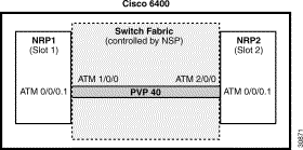
PVP Example: Configuring and Connecting Edge LSRs Within a Cisco 6400
In this example, two NRPs are configured as Edge LSRs in the same Cisco 6400. The Edge LSRs are connected to each other through a PVP through the switch fabric of the Cisco 6400, as shown in Figure 3-1.
Figure 3-1 PVP Connection Between Two Edge LSRs Within a Cisco 6400
The following example shows the configuration for NRP1 in Slot 1:
NRP1# configure terminal
NRP1(config)# ip cef
NRP1(config)# tag-switching ip
NRP1(config)# interface ATM0/0/0.1 tag-switching
NRP1(config-if)# ip unnumbered Loopback0
NRP1(config-if)# atm pvc 40 40 0 aal5snap
NRP1(config-if)# tag-switching atm vp-tunnel 40
NRP1(config-if)# tag-switching ip
The following example shows the configuration for NRP2 in Slot 2:
NRP2# configure terminal
NRP2(config)# ip cef
NRP2(config)# tag-switching ip
NRP2(config)# interface ATM0/0/0.1 tag-switching
NRP2(config-if)# ip unnumbered Loopback0
NRP2(config-if)# atm pvc 40 40 0 aal5snap
NRP2(config-if)# tag-switching atm vp-tunnel 40
NRP2(config-if)# tag-switching ip
To complete the PVP connection between NRP1 and NRP2 in Figure 1, the NSP must be configured to set the path through the switch fabric. The following example shows the VP-switch configuration for the NSP:
NSP# configure terminal
NSP(config)# interface ATM1/0/0
NSP(config-if)# atm pvp 40 interface ATM2/0/0 40
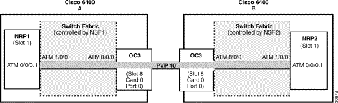
PVP Example: Configuring and Connecting Edge LSRs in Separate Cisco 6400s
In this example, two NRPs are configured as Edge LSRs in the separate Cisco 6400s. The Edge LSRs are connected to each other through a PVP through the MPLS network, as shown in Figure 3-2.
Figure 3-2 PVP Connection Between Two Edge LSRs in Separate Cisco 6400s
The following example shows the configuration for NRP1 in Slot 1 of Cisco 6400 A:
NRP1# configure terminal
NRP1(config)# ip cef
NRP1(config)# tag-switching ip
NRP1(config)# interface ATM0/0/0.1 tag-switching
NRP1(config-if)# ip unnumbered Loopback0
NRP1(config-if)# atm pvc 40 40 0 aal5snap
NRP1(config-if)# tag-switching atm vp-tunnel 40
NRP1(config-if)# tag-switching ip
The following example shows the configuration for NRP2 in Slot 1 of Cisco 6400 B:
NRP2# configure terminal
NRP2(config)# ip cef
NRP2(config)# tag-switching ip
NRP2(config)# interface ATM0/0/0.1 tag-switching
NRP2(config-if)# ip unnumbered Loopback0
NRP2(config-if)# atm pvc 40 40 0 aal5snap
NRP2(config-if)# tag-switching atm vp-tunnel 40
NRP2(config-if)# tag-switching ip
To complete the PVP connection between NRP1 and NRP2 in Figure 1, the NSPs must be configured to set the path through the switch fabric and node line cards (NLCs).
The following example shows the VP-switch configuration for NSP1 in Cisco 6400 A:
NSP1# configure terminal
NSP1(config)# interface ATM1/0/0
NSP1(config-if)# atm pvp 40 interface ATM8/0/0 40
The following example shows the VP-switch configuration for NSP2 in Cisco 6400 B:
NSP2# configure terminal
NSP2(config)# interface ATM1/0/0
NSP2(config-if)# atm pvp 40 interface ATM8/0/0 40
MPLS Edge LSRs Connected Through a VPI Range
In addition to providing transparent NSP redundancy, configuring a VPI Range to connect two MPLS Edge LSRs enables you to accommodate a large number of LVCs. For more information on VPI ranges, see the "Configuring a VPI Range" section in the "Configuring Tag Switching" chapter in the ATM Switch Router Software Configuration Guide.
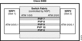
VPI Range Example: Configuring and Connecting Edge LSRs Within a Cisco 6400
In this example, two NRPs are configured as Edge LSRs in the same Cisco 6400. The Edge LSRs are connected to each other through a VPI range through the switch fabric of the Cisco 6400, as shown in Figure 3-3.
Figure 3-3 VPI Range Between Two Edge LSRs Within a Cisco 6400
The following example shows the configuration for NRP1 in Slot 1:
NRP1# configure terminal
NRP1(config)# ip cef
NRP1(config)# tag-switching ip
NRP1(config)# interface ATM0/0/0.1 tag-switching
NRP1(config-if)# ip unnumbered Loopback0
NRP1(config-if)# tag-switching atm vpi 7-10
NRP1(config-if)# tag-switching ip
The following example shows the configuration for NRP2 in Slot 2:
NRP2# configure terminal
NRP2(config)# ip cef
NRP2(config)# tag-switching ip
NRP2(config)# interface ATM0/0/0.1 tag-switching
NRP2(config-if)# ip unnumbered Loopback0
NRP2(config-if)# tag-switching atm vpi 7-10
NRP2(config-if)# tag-switching ip
To complete the VPI range connection between NRP1 and NRP2 in Figure 1, the NSP must be configured to set the paths through the switch fabric. PVP 0 is used to set up the control channels. The following example shows the VP-switch configuration for the NSP:
NSP# configure terminal
NSP(config)# interface ATM1/0/0
NSP(config-if)# atm pvp 7 interface ATM2/0/0 7
NSP(config-if)# atm pvp 8 interface ATM2/0/0 8
NSP(config-if)# atm pvp 9 interface ATM2/0/0 9
NSP(config-if)# atm pvp 10 interface ATM2/0/0 10
NSP(config-if)# atm pvp 0 interface ATM2/0/0 0
Note This example uses the default control channel PVC 0/32. You can also use a channel within the
configured VPI range by using the tag-switching atm control-vc interface configuration command on
the NRPs. For example, if you want to use the control channel PVC 7/32, then enter tag-switching atm
control-vc 7 32 on both NRP1 and NRP2.
VPI Range Example: Configuring and Connecting Edge LSRs in Separate Cisco 6400s
In this example, two NRPs are configured as Edge LSRs in the separate Cisco 6400s. The Edge LSRs are connected to each other through a VPI range through the MPLS network, as shown in Figure 3-4.
Figure 3-4 VPI Range Between Two NRPs in Different Cisco 6400s
The following example shows the configuration for NRP1 in Slot 1 of Cisco 6400 A:
NRP1# configure terminal
NRP1(config)# ip cef
NRP1(config)# tag-switching ip
NRP1(config)# interface ATM0/0/0.1 tag-switching
NRP1(config-if)# ip unnumbered Loopback0
NRP1(config-if)# tag-switching atm vpi 7-10
NRP1(config-if)# tag-switching ip
The following example shows the configuration for NRP2 in Slot 1 of Cisco 6400 B:
NRP2# configure terminal
NRP2(config)# ip cef
NRP2(config)# tag-switching ip
NRP2(config)# interface ATM0/0/0.1 tag-switching
NRP2(config-if)# ip unnumbered Loopback0
NRP2(config-if)# tag-switching atm vpi 7-10
NRP2(config-if)# tag-switching ip
To complete the VPI range connection between NRP1 and NRP2 in Figure 1, the NSPs must be configured to set the path through the switch fabric and node line cards (NLCs). PVP 0 is used to set up the control channels.
The following example shows the VP-switch configuration for NSP1 in Cisco 6400 A:
NSP# configure terminal
NSP(config)# interface ATM1/0/0
NSP(config-if)# atm pvp 7 interface ATM8/0/0 7
NSP(config-if)# atm pvp 8 interface ATM8/0/0 8
NSP(config-if)# atm pvp 9 interface ATM8/0/0 9
NSP(config-if)# atm pvp 10 interface ATM8/0/0 10
NSP(config-if)# atm pvp 0 interface ATM8/0/0 0
The following example shows the VP-switch configuration for NSP2 in Cisco 6400 B:
NSP# configure terminal
NSP(config)# interface ATM1/0/0
NSP(config-if)# atm pvp 7 interface ATM8/0/0 7
NSP(config-if)# atm pvp 8 interface ATM8/0/0 8
NSP(config-if)# atm pvp 9 interface ATM8/0/0 9
NSP(config-if)# atm pvp 10 interface ATM8/0/0 10
NSP(config-if)# atm pvp 0 interface ATM8/0/0 0
Note This example uses the default control channel PVC 0/32. You can also use a channel within the
configured VPI range by using the tag-switching atm control-vc interface configuration command on
the NRPs. For example, if you want to use the control channel PVC 7/32, then enter tag-switching atm
control-vc 7 32 on both NRP1 and NRP2.
MPLS Virtual Private Networks
For general MPLS VPN configuration tasks, examples, and command references, see the "Multiprotocol Label Switching" chapter in the Cisco IOS Switching Services Configuration Guide.
In addition to these configurations, you must configure the NSP to create paths through the switch fabric of the Cisco 6400. The switch fabric provides connectivity between the NRPs and the external ports on the node line cards (NLCs). For general configuration tasks, examples, and command references for configuring paths through the switch fabric, see the "Configuring Virtual Connections" chapter in the ATM Switch Router Software Configuration Guide.
The examples in this section illustrate the configurations necessary to enable MPLS VPN on a Cisco 6400.
Basic MPLS VPN Configuration Example
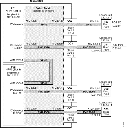
This section presents a basic Cisco 6400 MPLS VPN configuration. As shown in Figure 3-5, three customer edge (CE) routers are connected to the service provider backbone through three provider edge (PE) routers. Two of the PE routers are NRPs in the Cisco 6400, while the third PE router is a Cisco 7200. CE1 uses dual homing with PE1 and PE3.
CE1 and CE2 are devices in VPN1, while CE3 is in VPN2. PE1, or NRP1 in the Cisco 6400, handles the CE1 portion of VPN1. PE2, or NRP2 in the Cisco 6400, handles VPN2 as well as the CE2 portion of VPN1.
Figure 3-5 Basic Cisco 6400 MPLS VPN Topology
To enable a Cisco 6400 NRP to participate in a VPN, you must configure the NSP to create paths from the NRP through the Cisco 6400 switch fabric. The switch fabric provides the only connection between the NRP and an external port on a network line card (NLC). The switch fabric also provides the only connection between NRPs in the same Cisco 6400. Figure 3-6 shows a detailed schematic of the configuration used in the topology shown in Figure 3-5.
As shown in the accompanying configurations, you can use routed (in compliance with RFC 1483) PVCs for the CE to PE connections, as long as the CE router is capable of performing routing in compliance with RFC 1483 (aal5snap).
Note Each NRP in a Cisco 6400 is capable of handling multiple VPNs.
Figure 3-6 Detailed Schematic of the MPLS VPN Configuration Shown in Figure 3-5
PE1: Cisco 6400 NRP1
PE1 in Figure 3-6 is connected to PE3, through VP 42, and CE1, through PVC 35/70. In addition, PE1 and PE2, both NRPs in the same Cisco 6400, are connected to each other through VP40.
The following example shows the complete configuration for PE1 (Cisco 6400 NRP1):
!
ip cef
ip classless
!
interface Loopback0
ip address 10.10.10.10 255.255.255.255
no ip directed-broadcast
!
!The following fragment defines a VPN routing/forwarding (VRF) instance on PE1 !and imports routes from VPN2 to the VRF VPN1 routing table.
!
ip vrf vpn1
rd 100:1
route-target export 100:1
route-target import 100:1
route-target import 200:1
no tag-switching aggregate-statistics
!
!The following fragment creates VP 40 and VP 42 through the MPLS cloud.
!
interface ATM0/0/0.1 tag-switching
ip unnumbered Loopback0
no ip directed-broadcast
ip split-horizon
atm pvc 40 40 0 aal5snap
tag-switching atm vp-tunnel 40
tag-switching ip
!
interface ATM0/0/0.3 tag-switching
ip unnumbered Loopback0
no ip directed-broadcast
ip split-horizon
atm pvc 42 42 0 aal5snap
tag-switching atm vp-tunnel 42
tag-switching ip
!
!The following fragment associates an interface with a VRF on PE1.
!
interface ATM0/0/0.2 point-to-point
ip vrf forwarding vpn1
ip address 10.30.0.1 255.255.0.0
no ip directed-broadcast
ip split-horizon
atm pvc 70 35 70 aal5snap
!
!The following fragment configures Interior Gateway Protocol (IGP) routing on PE1.
!
router ospf 100
passive-interface ATM0/0/0.2
network 10.0.0.0 0.255.255.255 area 100
!
!The following fragment configures Routing Information Protocol (RIP)
!between PE1 and CE1. You can also use Border Gateway Protocol (BGP) or
!static routing instead of RIP.
!
router rip
version 2
!
address-family ipv4 vrf vpn1
version 2
redistribute bgp 100 metric transparent
network 10.30.0.0
no auto-summary
exit-address-family
!
!The following fragment configures internal BGP sessions among the PE routers.
!
router bgp 100
no synchronization
no bgp default ipv4-unicast
neighbor 10.11.11.11 remote-as 100
neighbor 10.11.11.11 update-source Loopback0
neighbor 10.12.12.12 remote-as 100
neighbor 10.12.12.12 update-source Loopback0
!
address-family ipv4 vrf vpn1
redistribute rip
no auto-summary
no synchronization
exit-address-family
!
address-family vpnv4
neighbor 10.11.11.11 activate
neighbor 10.11.11.11 send-community extended
neighbor 10.12.12.12 activate
neighbor 10.12.12.12 send-community extended
exit-address-family
!
PE2: Cisco 6400 NRP2
PE2 in Figure 3-6 is connected to CE2, through PVC 55/60, and CE3, through PVC 45/50. In addition, PE1 and PE2, both NRPs in the same Cisco 6400, are connected to each other through VP40.
The following example shows the complete configuration for PE2 (Cisco 6400 NRP2):
!
ip cef
ip classless
!
interface Loopback0
ip address 10.11.11.11 255.255.255.255
no ip directed-broadcast
!
!The following fragment defines the VRF instances on PE2. The fragment also
!imports the routes from VPN2 to the VRF VPN1 routing table and imports the
!routes from VPN1 to the VRF VPN2 routing table.
!
ip vrf vpn1
rd 100:1
route-target export 100:1
route-target import 100:1
route-target import 200:1
!
ip vrf vpn2
rd 200:1
route-target export 200:1
route-target import 200:1
route-target import 100:1
!
!The following fragment creates VP 40 through the MPLS cloud.
!
interface ATM0/0/0.1 tag-switching
ip unnumbered Loopback0
no ip directed-broadcast
ip split-horizon
atm pvc 40 40 0 aal5snap
tag-switching atm vp-tunnel 40
tag-switching ip
!
!The following fragment associates interfaces with VRFs on PE2.
!
interface ATM0/0/0.2 point-to-point
ip vrf forwarding vpn2
ip address 10.32.0.1 255.255.0.0
no ip directed-broadcast
ip split-horizon
atm pvc 50 45 50 aal5snap
!
interface ATM0/0/0.3 point-to-point
ip vrf forwarding vpn1
ip address 10.31.0.1 255.255.0.0
no ip directed-broadcast
ip split-horizon
atm pvc 60 55 60 aal5snap
!
!The following fragment configures IGP routing on PE2.
!
router ospf 100
passive-interface ATM0/0/0.2
passive-interface ATM0/0/0.3
network 10.11.0.0 0.0.255.255 area 100
!
!The following fragment configures RIP between PE2 and CE2, as well as
!between PE2 and CE3. You can also use Border Gateway Protocol (BGP) or
!static routing instead of RIP.
!
router rip
version 2
!
address-family ipv4 vrf vpn2
version 2
redistribute bgp 100 metric transparent
network 10.32.0.0
no auto-summary
exit-address-family
!
address-family ipv4 vrf vpn1
version 2
redistribute bgp 100 metric transparent
network 10.31.0.0
no auto-summary
exit-address-family
!
!The following fragment configures internal BGP sessions among the PE routers.
!
router bgp 100
no synchronization
no bgp default ipv4-unicast
neighbor 10.10.10.10 remote-as 100
neighbor 10.10.10.10 update-source Loopback0
neighbor 10.12.12.12 remote-as 100
neighbor 10.12.12.12 update-source Loopback0
!
address-family ipv4 vrf vpn2
redistribute rip
no auto-summary
no synchronization
exit-address-family
!
address-family ipv4 vrf vpn1
redistribute rip
no auto-summary
no synchronization
exit-address-family
!
address-family vpnv4
neighbor 10.10.10.10 activate
neighbor 10.10.10.10 send-community extended
neighbor 10.12.12.12 activate
neighbor 10.12.12.12 send-community extended
exit-address-family
!
PE1 and PE2 Connectivity: Cisco 6400 NSP
The following example shows the configuration necessary for the PE Cisco 6400 NSP to create the paths in the switch fabric between the NRPs and the OC3 line cards shown in Figure 3-6.
!The following fragment creates VP 42 between
!an OC3 (slot 8, card 1, port 0) and NRP1.
!
interface ATM8/1/0
atm pvp 42 interface ATM1/0/0 42
!
!The following fragment creates PVC 35/70 between
!an OC3 (slot 8, card 0, port 0) and NRP1.
!
interface ATM8/0/0
atm pvc 35 70 interface ATM1/0/0 35 70
!
!The following fragment creates VP 40 between NRP1 in Slot 1
!and NRP2 in Slot 3.:
!
interface ATM3/0/0
atm pvp 40 interface ATM1/0/0 40
!
!The following fragment creates PVC 55/60 between
!an OC3 (slot 8, card 1, port 1) and NRP2.
!
interface ATM8/1/1
atm pvc 55 60 interface ATM3/0/0 55 60
!
!The following fragment creates PVC 45/50 between
!an OC3 (slot 8, card 0, port 1) and NRP2.
!
interface ATM8/0/1
atm pvc 45 50 interface ATM3/0/0 45 50
!
PE3: Cisco 7200
PE3 in Figure 3-6 is connected to PE1, through VP 42, and CE1, through a packet over SONET (POS) link.
The following example shows the complete configuration for PE3 (Cisco 7200):
ip cef
ip classless
!
interface Loopback0
ip address 10.12.12.12 255.255.255.255
no ip directed-broadcast
!
!The following fragment defines the VRF instances on PE3.
!
ip vrf vpn1
rd 100:1
route-target export 100:1
route-target import 100:1
route-target import 200:1
isdn voice-call-failure 0
!
!The following fragment associates a POS interface with a VRF on PE3.
!
interface POS3/0
ip vrf forwarding vpn1
ip address 10.33.0.1 255.255.0.0
no ip directed-broadcast
no keepalive
clock source internal
!
!The following fragment creates VP 42 through the MPLS cloud.
!
interface ATM2/0.1 tag-switching
ip unnumbered Loopback0
no ip directed-broadcast
ip split-horizon
atm pvc 42 42 0 aal5snap
tag-switching atm vp-tunnel 42
tag-switching ip
!
!The following fragment configures IGP routing on PE3.
!
router ospf 100
passive-interface POS3/0
network 10.12.0.0 0.0.255.255 area 100
!
!The following fragment configures RIP between PE3 and CE1.
!You can also use BGP or static routing instead of RIP.
!
router rip
version 2
!
address-family ipv4 vrf vpn1
version 2
redistribute bgp 100 metric transparent
network 10.33.0.0
no auto-summary
exit-address-family
!
!The following fragment configures internal BGP sessions
!among the PE routers.
!
router bgp 100
no synchronization
no bgp default ipv4-unicast
neighbor 10.10.10.10 remote-as 100
neighbor 10.10.10.10 update-source Loopback0
neighbor 10.11.11.11 remote-as 100
neighbor 10.11.11.11 update-source Loopback0
!
address-family ipv4 vrf vpn1
redistribute rip
no auto-summary
no synchronization
exit-address-family
!
address-family vpnv4
neighbor 10.10.10.10 activate
neighbor 10.10.10.10 send-community extended
neighbor 10.11.11.11 activate
neighbor 10.11.11.11 send-community extended
exit-address-family
!
CE1: Cisco 7500
CE1 in Figure 3-6 is connected to PE1, through PVC 35/70, and PE3, through a packet over SONET (POS) link.
The following example shows the configuration for CE1 (Cisco 7500):
!
ip cef
ip classless
!
interface Loopback0
ip address 10.13.13.13 255.255.255.255
no ip directed-broadcast
!
!The following fragment creates the POS link between CE1 and PE3.
!
interface POS4/0/0
ip address 10.33.0.2 255.255.0.0
no ip directed-broadcast
no ip route-cache distributed
no keepalive
clock source internal
!
!The following fragment creates PVC 35/70.
!
interface ATM2/0/0.2 point-to-point
ip address 10.30.0.2 255.255.0.0
no ip directed-broadcast
ip split-horizon
atm pvc 70 35 70 aal5snap
!
!The following fragment configures RIP on CE1.
!You can also use BGP or static routing instead of RIP:
!
router rip
version 2
network 10.13.0.0
network 10.30.0.0
network 10.33.0.0
!
CE2: Cisco 7200
CE2 in Figure 3-6 is connected to PE2, through PVC 55/60.
The following example shows the configuration for the CE2 (Cisco 7200):
!
ip cef
ip classless
!
interface Loopback0
ip address 10.15.15.15 255.255.255.255
no ip directed-broadcast
!
!The following fragment creates PVC 55/60.
!
interface ATM2/0.2 point-to-point
ip address 10.31.0.2 255.255.0.0
no ip directed-broadcast
ip split-horizon
atm pvc 60 55 60 aal5snap
!
!The following fragment configures RIP on CE2.
!You can also use BGP or static routing instead of RIP:
!
router rip
version 2
network 10.15.0.0
network 10.31.0.0
!
CE3: Cisco 7500
CE3 in Figure 3-6 is connected to PE2, through PVC 45/50.
The following example shows the configuration for CE3 (Cisco 7500):
!
ip cef
ip classless
!
interface Loopback0
ip address 10.14.14.14 255.255.255.255
no ip directed-broadcast
!
!The following fragment creates PVC 45/50.
!
interface ATM1/0/0.1 point-to-point
ip address 10.32.0.2 255.255.0.0
no ip directed-broadcast
ip split-horizon
atm pvc 50 45 50 aal5snap
!
!The following fragment configures RIP on CE3.
!You can also use BGP or static routing instead of RIP.
!
router rip
version 2
network 10.14.0.0
network 10.32.0.0
!
Split Horizon and RIP Example
Note Split horizon is disabled by default on ATM interfaces. If you are running RIP in your VPNs, you must
enable split horizon.
The following example shows a typical configuration for an ATM subinterface on an NRP: