|
|

This appendix provides information about connectors and pinouts for configuration of the Cisco 6260 system.
Ten female RJ-21 (Champ) subscriber connectors are located at the top of the Cisco 6260 chassis, facing forward. These 50-pin sockets provide the DSL subscriber connections. Each subscriber connector serves three line card slots. This connection can be made by either of the following methods:
Figure C-1 shows connector pin locations for the xDSL Champ connectors. Pin locations are the same for all Champ connectors.

This section provides information about the external interface connectors for the Cisco 6260 I/O module.
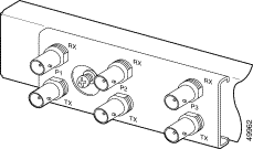
Three sets of two vertically paired E3 75-ohm coaxial BNC connectors reside on the left side of the I/O module faceplate. The P1 connectors serve as the network trunk connections. The P2 and P3 connectors support subtending to additional Cisco 6260 chassis. Each set has both a receive (RX) connector and a transmit (TX) connector.
Figure C-2 shows a close-up of the E3 connectors.

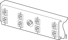
Four sets of two vertically paired E1120-ohm RJ-48c connectors are located on the left side of the I/O module faceplate. Each E1 interface can be used as a WAN trunk connection, an individual E1 subtend link, a connection to an IMA subtending group, or a connection to an IMA group trunk interface.
Figure C-3 shows a close-up of the E1 connectors.

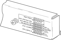
There are 36 wire-wrap pins located on the right side of each I/O module faceplate that support
Table C-1 lists the pinout descriptions for the I/O module wire-wrap pins and Figure C-4 shows a close-up of the I/O module wire-wrap pins.
| Pin | Row 1 | Row 2 | Row 3 | Row 4 | Row 5 | Row 6 |
|---|---|---|---|---|---|---|
1 | AUD_MIN5_CO | Reserved | RX_BITS8_TIPA | |||
2 | PEM1_BR_NO | AUD_CRIT_NO | AUD_MIN_NO | VIS_MAJ_NO | Reserved | RX_BITS_RINGA |
3 | PEM1_BR_NC | AUD_CRIT_NC | AUD_MIN_NC | VIS_MAJ_NC | Reserved | RX_BITS_GND/GND |
4 | PEM2_BR_CO | AUD_MAJ_CO | VIS_CRIT_CO | VIS_MIN_CO | Reserved | RX_BITS_TIPB |
5 | PEM2_BR_NO | AUD_MAJ_NO | VIS_CRIT_NO | VIS_MIN_NO | ACO_NO | RX_BITS_RINGB |
6 | PEM2_BR_NC | AUD_MAJ_NC | VIS_CRIT_NC | VIS_MIN_NC | GND | RX_BITS_GND/GND |
| 1PEM = power entry module 2BR = breaker 3AUD = audible 4CRIT = critical alarm 5MIN = minor alarm 6VIS = visible 7MAJ = major alarm 8RX_BITS = receive building-integrated timing source |

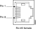
The console and auxiliary ports, which are two identical serial EIA/TIA-232 ports, use RJ-48 receptacle connectors on the NI-2 card faceplate. Table C-2 shows the pin assignments, and Figure C-5 shows an RJ-48 receptacle connector.
| Pin Number | Signal |
|---|---|
1 | RTS |
2 | DTR |
3 | TXD |
4 | GND |
5 | GND |
6 | RXD |
7 | DSR |
8 | CTS |

The Ethernet port, a 10BaseT interface with an RJ-48 receptacle connector, is on the NI-2 card faceplate. It is used to connect the Cisco 6260 to the management station, a Sun SPARCstation running Cisco DSL Manager (CDM) software. Table C-3 shows the pin assignments, and Figure C-6 shows an NI-2 card Ethernet connector.
| Pin Number | Signal |
|---|---|
1 | TX+ |
2 | TX- |
3 | RX+ |
4 | Unused |
5 | Unused |
6 | RX- |
7 | Unused |
8 | Unused |

![]()
![]()
![]()
![]()
![]()
![]()
![]()
![]()
Posted: Mon Dec 9 08:40:22 PST 2002
All contents are Copyright © 1992--2002 Cisco Systems, Inc. All rights reserved.
Important Notices and Privacy Statement.