|
|

Product Numbers: PS-6200-1-16NA and PS-6200-2-16NA
This document, which is for use by telephone company personnel, describes the installation of the Central Office (CO) POTS (plain old telephone service) splitter. The CO POTS splitter can be used with the Cisco 6200 digital subscriber line access multiplexer (DSLAM).
The following sections are included in this configuration note:
The CO POTS splitter is a set of filters packaged in an enclosure (chassis). It is suitable for use in a central office (CO) Main Distribution Frame (MDF).
The CO POTS splitter
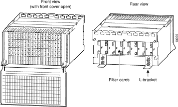
There are 8 circuit boards with 2 ports per board for a total of 16 splitter filters in the CO POTS splitter chassis (see Figure 1).
The CO POTS splitter also contains a safety protection circuit that meets GR-1089-CORE safety requirements.
 | Caution This safety protection circuit is fused. Extremely hazardous situations can result in a blown fuse, causing failure of the POTS splitter. |
The CO POTS splitter comes as a wire-wrap version (PS-6200-1-16NA). A punch-down version (PS-6200-2-16NA) also can be ordered.
Each CO POTS splitter has a protective front cover, which snaps on and off easily, and shields connections from wire clippings and other debris. Jumper wires are routed through front and rear fanning strips. The front slots are aligned with the wire-dressing channels between terminal rows. This allows rapid cross-connect wire identification and promotes orderly dressing.
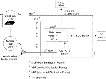
In a typical deployment, the CO POTS splitter is located in the DSL service provider's CO. Copper loops enter the CO in bundles, terminating at the MDF. The provider extends the ADSL tip/ring wire pairs to the horizontal distribution frame (HDF) where the CO POTS splitter, which splits the voice and ADSL traffic, is mounted. The voice pairs are wired from the CO splitter to the CO switch. The ADSL pairs are wired from the CO splitter to the DSLAM (see Figure 2).
The following mounting hardware is provided with each CO POTS splitter:
The CO POTS splitter is typically located in an HDF within a CO MDF. The following sections describe the installation and replacement procedures for the CO POTS splitter.
To install the CO POTS splitter chassis in an HDF within the MDF, follow these steps:
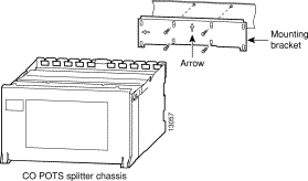
Step 1 Install the mounting bracket on a frame by placing it horizontally or vertically with one of the arrows in an up position (see Figure 3).
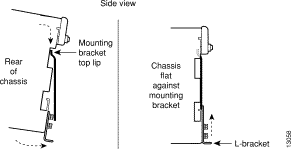
Step 2 Place the chassis on the top lip of the bracket (see Figure 4).
Step 3 Rotate the chassis inward until it is flat against the mounting bracket (see Figure 4).
Step 4 Lock the chassis into place by pushing the L-bracket up and tightening the L-bracket screws (see Figure 4).
This completes the installation procedure.
The CO POTS splitter's filter cards are field replaceable units (FRUs). To remove and replace a filter card in the CO POTS splitter, follow these steps.
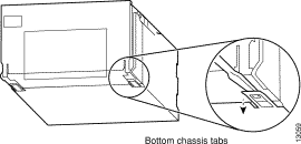
Step 1 Pry down the tabs that are on the bottom of the chassis, using a flat blade screwdriver (see Figure 5).
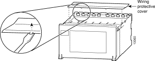
Step 2 Remove the wiring protective cover (located on top of the chassis) with a flat blade screwdriver (see Figure 6).
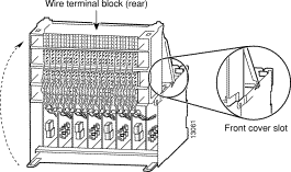
Step 3 Open the unit by pushing the front panel of the chassis upward and sliding the top of the panel into the slots at the top of the chassis (see Figure 7).
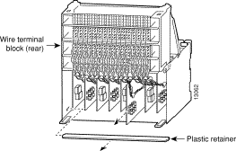
Step 4 Replace the card by performing the following tasks (see Figure 8):
(a) Bend and then remove the plastic retainer.
(b) Disconnect the wire-wrapped connection from the rear of the wire terminal block.
(c) Slide out the old card.
(d) Slide in the new card.
(e) Make the wire-wrapped connection to the rear of the wire terminal block.
(f) Replace the plastic retainer.
Step 5 Replace the top cover when the installation is complete.
This completes the card removal and replacement procedure.
To remove and replace the front cover of a CO POTS splitter, follow these steps:
Step 1 Partially open the cover and press down on the open end of one hinge to unsnap it from the hinge pin.
Step 2 While holding the cover partially open, rotate it down to unsnap the other hinge.
Step 3 To replace the cover, hold it in a partially open position and press up against the bottom of each hinge to snap it into each pin.
This completes the front cover removal and replacement procedure.
To connect a Cisco 6200 DSLAM subscriber line card (SLC) to the CO POTS splitter chassis, use the following steps.
Step 1 Locate a 25-pair cable of the desired length that has a female Champ connector attached to it.
Step 2 Confirm that the female Champ connector is wired according to the color coded pin assignments specified in Appendix A of the Cisco 6200 User Guide.
Step 3 Connect the female end of the cable to the desired slot connector on the back of the Cisco 6200 chassis.
Step 4 Fan out the twisted pairs on the non-Champ end of the cable.
Step 5 Wire the individual twisted pairs directly to the xDSL (DSL collective technologies) wire wrap pins on the POTS splitter. Use the wiring information in Table 1 and Table 2.
Step 6 Connect each subscriber's POTS tip/ring pair to the CO switch.
Step 7 Connect each subscriber's line tip/ring pair to the appropriate outside loop for that subscriber.
For board No. 1, use Table 1, performing Steps 1 to 7.
| Port No. | Wire Color | Subscriber Line | xDSL |
|---|---|---|---|
0 | White/blue | 1 | Tip |
0 | Blue/white | 1 | Ring |
1 | White/orange | 2 | Tip |
1 | Orange/white | 2 | Ring |
2 | White/green | 3 | Tip |
2 | Green/white | 3 | Ring |
3 | White/brown | 4 | Tip |
3 | Brown/white | 4 | Ring |
4 | White/gray | 5 | Tip |
4 | Gray/white | 5 | Ring |
5 | Red/blue | 6 | Tip |
5 | Blue/red | 6 | Ring |
6 | Red/orange | 7 | Tip |
6 | Orange/red | 7 | Ring |
7 | Red/green | 8 | Tip |
7 | Green/red | 8 | Ring |
For board No. 2, use Table 2, repeating Steps 1 to 7.
| Port No. | Wire Color | Subscriber Line | xDSL |
|---|---|---|---|
0 | White/blue | 9 | Tip |
0 | Blue/white | 9 | Ring |
1 | White/orange | 10 | Tip |
1 | Orange/white | 10 | Ring |
2 | White/green | 11 | Tip |
2 | Green/white | 11 | Ring |
3 | White/brown | 12 | Tip |
3 | Brown/white | 12 | Ring |
4 | White/gray | 13 | Tip |
4 | Gray/white | 13 | Ring |
5 | Red/blue | 14 | Tip |
5 | Blue/red | 14 | Ring |
6 | Red/orange | 15 | Tip |
6 | Orange/red | 15 | Ring |
7 | Red/green | 16 | Tip |
7 | Green/red | 16 | Ring |
This section lists safety guidelines you should follow when you are working with any equipment that connects to electrical power or telephone wiring.
Safety warnings appear throughout this publication in procedures that, if performed incorrectly, may harm you. A warning symbol precedes each warning statement.
 | Warning Means danger. You are in a situation that could cause bodily injury. Before you work on any equipment, be aware of the hazards involved with electrical circuitry and be familiar with standard practices for preventing accidents. To see translations of the warnings that appear in this publication, refer to the Regulatory Compliance and Safety Information document that accompanied this device. |
Waarschuwing Dit waarschuwingssymbool betekent gevaar. U verkeert in een situatie die lichamelijk letsel kan veroorzaken. Voordat u aan enige apparatuur gaat werken, dient u zich bewust te zijn van de bij elektrische schakelingen betrokken risico's en dient u op de hoogte te zijn van standaard maatregelen om ongelukken te voorkomen. Voor vertalingen van de waarschuwingen die in deze publicatie verschijnen, kunt u het document Regulatory Compliance and Safety Information (Informatie over naleving van veiligheids- en andere voorschriften) raadplegen dat bij dit toestel is ingesloten.
Varoitus Tämä varoitusmerkki merkitsee vaaraa. Olet tilanteessa, joka voi johtaa ruumiinvammaan. Ennen kuin työskentelet minkään laitteiston parissa, ota selvää sähkökytkentöihin liittyvistä vaaroista ja tavanomaisista onnettomuuksien ehkäisykeinoista. Tässä julkaisussa esiintyvien varoitusten käännökset löydät laitteen mukana olevasta Regulatory Compliance and Safety Information -kirjasesta (määräysten noudattaminen ja tietoa turvallisuudesta).
Attention Ce symbole d'avertissement indique un danger. Vous vous trouvez dans une situation pouvant causer des blessures ou des dommages corporels. Avant de travailler sur un équipement, soyez conscient des dangers posés par les circuits électriques et familiarisez-vous avec les procédures couramment utilisées pour éviter les accidents. Pour prendre connaissance des traductions d'avertissements figurant dans cette publication, consultez le document Regulatory Compliance and Safety Information (Conformité aux règlements et consignes de sécurité) qui accompagne cet appareil.
Warnung Dieses Warnsymbol bedeutet Gefahr. Sie befinden sich in einer Situation, die zu einer Körperverletzung führen könnte. Bevor Sie mit der Arbeit an irgendeinem Gerät beginnen, seien Sie sich der mit elektrischen Stromkreisen verbundenen Gefahren und der Standardpraktiken zur Vermeidung von Unfällen bewußt. Übersetzungen der in dieser Veröffentlichung enthaltenen Warnhinweise finden Sie im Dokument Regulatory Compliance and Safety Information (Informationen zu behördlichen Vorschriften und Sicherheit), das zusammen mit diesem Gerät geliefert wurde.
Avvertenza Questo simbolo di avvertenza indica un pericolo. La situazione potrebbe causare infortuni alle persone. Prima di lavorare su qualsiasi apparecchiatura, occorre conoscere i pericoli relativi ai circuiti elettrici ed essere al corrente delle pratiche standard per la prevenzione di incidenti. La traduzione delle avvertenze riportate in questa pubblicazione si trova nel documento Regulatory Compliance and Safety Information (Conformità alle norme e informazioni sulla sicurezza) che accompagna questo dispositivo.
Advarsel Dette varselsymbolet betyr fare. Du befinner deg i en situasjon som kan føre til personskade. Før du utfører arbeid på utstyr, må du vare oppmerksom på de faremomentene som elektriske kretser innebærer, samt gjøre deg kjent med vanlig praksis når det gjelder å unngå ulykker. Hvis du vil se oversettelser av de advarslene som finnes i denne publikasjonen, kan du se i dokumentet Regulatory Compliance and Safety Information (Overholdelse av forskrifter og sikkerhetsinformasjon) som ble levert med denne enheten.
Aviso Este símbolo de aviso indica perigo. Encontra-se numa situação que lhe poderá causar danos físicos. Antes de começar a trabalhar com qualquer equipamento, familiarize-se com os perigos relacionados com circuitos eléctricos, e com quaisquer práticas comuns que possam prevenir possíveis acidentes. Para ver as traduções dos avisos que constam desta publicação, consulte o documento Regulatory Compliance and Safety Information (Informação de Segurança e Disposições Reguladoras) que acompanha este dispositivo.
¡Advertencia! Este símbolo de aviso significa peligro. Existe riesgo para su integridad física. Antes de manipular cualquier equipo, considerar los riesgos que entraña la corriente eléctrica y familiarizarse con los procedimientos estándar de prevención de accidentes. Para ver una traducción de las advertencias que aparecen en esta publicación, consultar el documento titulado Regulatory Compliance and Safety Information (Información sobre seguridad y conformidad con las disposiciones reglamentarias) que se acompaña con este dispositivo.
Varning! Denna varningssymbol signalerar fara. Du befinner dig i en situation som kan leda till personskada. Innan du utför arbete på någon utrustning måste du vara medveten om farorna med elkretsar och känna till vanligt förfarande för att förebygga skador. Se förklaringar av de varningar som förkommer i denna publikation i dokumentet Regulatory Compliance and Safety Information (Efterrättelse av föreskrifter och säkerhetsinformation), vilket medföljer denna anordning.
Follow these basic guidelines when working with any electrical equipment:
Use the following guidelines when working with any equipment that is connected to telephone wiring or to other network cabling:
The CO POTS splitter meets NEBS Level 3 requirements as described in GR-63-CORE and has been tested and approved by Bellcore for GR-1089-CORE. It also meets T1.413 POTS performance requirements.
Cisco Connection Online (CCO) is Cisco Systems' primary, real-time support channel. Maintenance customers and partners can self-register on CCO to obtain additional information and services.
Available 24 hours a day, 7 days a week, CCO provides a wealth of standard and value-added services to Cisco's customers and business partners. CCO services include product information, product documentation, software updates, release notes, technical tips, the Bug Navigator, configuration notes, brochures, descriptions of service offerings, and download access to public and authorized files.
CCO serves a wide variety of users through two interfaces that are updated and enhanced simultaneously: a character-based version and a multimedia version that resides on the World Wide Web (WWW). The character-based CCO supports Zmodem, Kermit, Xmodem, FTP, and Internet e-mail, and it is excellent for quick access to information over lower bandwidths. The WWW version of CCO provides richly formatted documents with photographs, figures, graphics, and video, as well as hyperlinks to related information.
You can access CCO in the following ways:
For a copy of CCO's Frequently Asked Questions (FAQ), contact cco-help@cisco.com. For additional information, contact cco-team@cisco.com.
![]()
![]()
![]()
![]()
![]()
![]()
![]()
![]()
Posted: Sat Sep 28 04:31:33 PDT 2002
All contents are Copyright © 1992--2002 Cisco Systems, Inc. All rights reserved.
Important Notices and Privacy Statement.