|
|

Product Number: CSC-R16M= and MC-R16M-V3.4=
The CSC-R16M Token Ring interface card interconnects routers and terminal servers to IEEE-802.5 and IBM Token Ring media from either a 16-megabits per second (Mbps) or 4-Mbps Token Ring LAN. A single jumper setting permits the user to configure the card with either speed (4 or 16 Mbps). The CSC-R16M supports a single Token Ring interface.
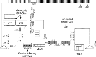
Figure 1 shows the CSC-R16M Token Ring interface card viewed from the component side with its jumpers configured according to the factory settings. The enlargement in Figure 1 is a close-up view of the factory-default jumper settings on that part of the card.

This publication includes the procedures required to install and configure a CSC-R16M Token Ring card in any chassis type that can use this card. Also included are the procedures to upgrade the following:
The same procedure is used for both of these upgrades because to upgrade a CSC-R16 to a CSC-R16M requires replacing the microcode EPROMs on the CSC-R16 with Microcode
Version 3.0 or later. There are no additional hardware changes to the CSC-R16 card. The first sections of this publication include the following basic configuration and safety information:
If you are installing a new CSC-R16M card, upgrading your CSC-R16 card to a CSC-R16M card, or replacing the microcode on your CSC-R16M card, use these sections to ensure the correct installation or upgrade of your CSC-R16M card.
Following are configuration and safety considerations for the CSC-R16M Token Ring interface card.
The speed of the CSC-R16M interface card is user-configurable. CSC-R16M interface cards are shipped configured to run at 16 Mbps. Jumper area J22 configures the CSC-R16M for either 4-Mbps or 16-Mbps operation as follows (see Figure 1):
The jumper to use at jumper area J22 is supplied and placed on the posts at jumper area J21.
 | Warning Setting the speed jumper (J22) to an incompatible speed for the Token Ring network causes no damage to the card; however, the entire Token Ring network will not function for the time that the misconfigured card is attempting to use the ring. This is true of all speed-selectable Token Ring cards. |
Card numbers must be unique within the set of all CSC-R16M interface cards in the same chassis. Card numbering allows the system to distinguish one CSC-R16M interface card from another. (The same is true for most types of Multibus cards in the system.)
Software-readable dual-in-line package (DIP) switches, located on the front edge of the card, control the card number of the CSC-R16M card within the router. Configure the switches as in Table 1 to select the desired card number. Figure 2 shows the numbered positions of the DIP switches viewed from the front edge of the card.
| Switches1 | |||
|---|---|---|---|
| Card Number | 1 | 2 | 3 |
| 0 | Down2 | Down | Down |
| 1 | Up | Down | Down |
| 2 | Down | Up | Down |
| 3 | Up | Up | Down |
| 4 | Down | Down | Up |
| 5 | Up | Down | Up |
| 6 | Down | Up | Up |

The unit address of the CSC-R16M interface is selected by the system, but can be anticipated by you, which will help you to establish which interface will be assigned and therefore, which card number to assign the card. CSC-R16M unit addresses begin after CSC-R unit addresses, but before CSC-1R and CSC-2R unit addresses.
For example, if there is already one CSC-R card and one CSC-1R card in the chassis (set as card numbers 1 and 2, respectively), and you add one CSC-R16M card (set as card number 3), the system will assign unit address 0 to the CSC-R interface, unit address 1 to the CSC-R16M interface, and unit address 2 to the CSC-1R interface. Making card numbers match unit addresses is recommended to monitor which unit address is on each card.
The CSC-R16M interoperates with the 4 Mbps CSC-R Token Ring interface card, with any of the MCI family of cards, and with any cards in the ciscoBus or ciscoBus2 complex. The CSC-R16M interface card will also work with the CSC-16 card for use with a Token Ring communication server. The CSC-R16M Token Ring interface card will operate from any slot in the chassis.
Along the front edge of the CSC-R16M card are 13 red LEDs and one green LED (see Figure 3). The descriptions of their functions and layout are shown in Table 2.

| LED | Function |
|---|---|
| A | Processor halted (normally off) |
| B | -12 volts fused |
| C | +12 volts fused |
| D | + 5 volts fused |
| E | + 5 volts (power) |
| F-M | Activity lights1 |
| N | Run light (green) |
Following is the power budget for the CSC-R16M Token Ring interface card:
Electrostatic discharge damage (ESD) occurs when electronic printed circuit cards are improperly handled and can result in complete or intermittent failures. ESD can impair electronic circuitry and equipment. Always follow ESD prevention procedures when removing and replacing cards. Following are steps for handling printed circuit cards:
Step 1 Slip on an ESD-preventive wrist strap, ensuring that it makes good skin contact.
Step 2 Connect the strap to an unpainted chassis frame surface or another proper grounding point or surface to safely channel unwanted ESD voltages to ground.
Step 3 Use the ejectors to remove the card. Handle the card by its sides. Place the card on an antistatic surface or in a static shielding bag. To prevent further damage to the card by ESD voltages, defective cards must remain in the static shielding bag when returned for repair or replacement.
Step 4 Handling the new card by its edges only, insert it into the chassis. Avoid contact between the card and clothing. The wrist strap only protects the card from ESD voltages on the body; ESD voltages on clothing can still damage the card.
 | Caution Use an ohmmeter to check the ESD-preventive wrist strap to ensure that the resistor is providing proper ESD protection. For safety, the measurement should be in the range 1 to 10 mega ohms. |
Installation and upgrade procedures for the CSC-R16M card are included in the following sections, but before you can install or upgrade a card, you must gain access to the chassis card cage.
Following are the procedures for accessing the interior of the chassis types that can use the CSC-R16M card:
Select the procedure that matches your chassis type. Before beginning read the entire procedure.
Following is the procedure for accessing the A-type chassis card cage.
This procedure requires a Number 1 Phillips screwdriver.
 | Warning Before accessing the chassis interior and removing any cards, turn off power to prevent electrical shock hazard. Attach appropriate ESD protection before beginning this procedure. |
Step 1 Turn OFF power to the chassis, but to channel ESD voltages to ground, do not unplug it.
Step 2 Remove the front access panel and set it aside. (See Figure 4.)
Step 3 Proceed with this step only if you will install Token Ring appliques--Locate and remove the seven cover screws that secure the chassis top cover. Set the cover and screws aside.

If you are installing a CSC-R16M card, verify the Token Ring speed and card number and then proceed to the section, "Installing the CSC-R16M Card," on page 8.
If you are upgrading a CSC-R16 card to a CSC-R16M or upgrading the microcode EPROM on the CSC-R16M card, proceed to the section, "Upgrading the Microcode EPROM," on page 9.
Following is the procedure for accessing the M chassis card cage.
This procedure requires a Number 1 Phillips screwdriver and a medium-size flat-blade screwdriver.
 | Warning Before accessing the chassis interior and removing any cards, turn off power to prevent electrical shock hazard. Attach appropriate ESD protection before beginning this procedure. |
Step 1 Turn OFF power to the chassis, but to channel ESD voltages to ground, do not unplug it.
Step 2 Locate the three slotted screws that secure the top of the card cage access panel. Use the flat-blade screwdriver to turn each of these screws 1/4 to 1/2 turn counterclockwise until the screws pop up.
Step 3 Loosen the three Phillips screws at the bottom edge of the card cage access panel (do not remove these screws completely).
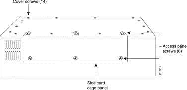
Step 4 Proceed with this step only if you will install Token Ring appliques--Locate and remove the 14 screws that secure the top cover of the M chassis. (See Figure 5.) Set the cover and screws aside.

Step 5 Carefully remove the access panel and set it aside.
If you are installing a CSC-R16M card, verify the Token Ring speed and card number and then proceed to the section, "Installing the CSC-R16M Card," on page 8.
If you are upgrading a CSC-R16 card to a CSC-R16M or upgrading the microcode EPROM on the CSC-R16M card, proceed to the section, "Upgrading the Microcode EPROM," on page 9.
Following is the procedure for installing the CSC-R16M card. If the chassis is rack mounted, remove it from the rack to perform this installation.
Step 1 Power OFF the unit and unplug it.
Step 2 Proceed to step 4 if you do not need to install a Token Ring applique for your new
CSC-R16M card--To install a Token Ring applique, attach the Token Ring applique plate (cable attached) to the inside of the appropriate rear panel plate area. This applique connector provides the 9-pin D-type Token Ring attachment to the network.
Step 3 Route the Token Ring cable (attached to the applique) underneath the chassis card cage. Do not crimp or bend the Token Ring cable or any other cables located underneath the chassis card cage.
Step 4 Remove any cables (in the front of the chassis card cage) that would impede the removal of the old CSC-R16M card. Note their positions.
Step 5 Remove the old CSC-R16M card.
Step 6 Insert the new CSC-R16M card into the appropriate card cage slot.
Step 7 Attach cables. The CSC-R16M card offers a 10-pin DIP header cable attachment and a keyed connector as shown in Figure 6. Internally, connect the Token Ring cable (for each applique and card) to the port on the appropriate CSC-R16M card.
Step 8 Externally, connect a Token Ring cable to the 9-pin Token Ring applique connector.

 | Warning To prevent bringing down your Token Ring network, make certain that the Token Ring-speed setting on your CSC-R16M card matches the speed of the Token Ring network to which the interface is connected, before you apply power to your chassis. A speed mismatch can bring down your Token Ring network. |
Step 9 Turn ON power to the chassis and allow the system to boot for an installation check.
Step 10 Use the show interface token and show controller token commands to verify that your CSC-R16M Token Ring interface is acknowledged by the system. For more information on the show interface token and show controller token commands, refer to the appropriate Configuration and Reference publication.
Step 11 After you verify the presence of the CSC-R16M Token Ring interface, replace the card access panel and top cover (if removed) on the A+, A, or M chassis.
The system is ready to install in the network.
This section describes the procedure required to either upgrade a CSC-R16 Token Ring card to a CSC-R16M, or to simply upgrade the microcode EPROMs on a CSC-R16M card. Both upgrades require changing the two erasable programmable read-only memory (EPROM) devices on the
card and include the following:
Upgrading to CSC-R16M Microcode Version 3.2 (or later) requires System Software Versions 8.3(6), 9.0(4), or 9.1(2) or later. If you require one of these system software versions, contact your service representative.
Following are the tools and parts required for these procedures:
The following upgrade procedure is used for both the CSC-R16 to CSC-R16M upgrade and the CSC-R16M microcode upgrade. In this procedure, the CSC-R16 and CSC-R16M cards are referred to as the card.
Following is the procedure for upgrading the microcode EPROMs.
 | Caution To prevent ESD damage, attach appropriate ESD protection before starting this procedure. |
Step 1 Disconnect any cables preventing the removal of the card, and remove the card from the chassis card cage.
Step 2 Position the card as shown in Figure 7. The two EPROMs, labeled SBEMON, are located next to one another with the notched end toward your left.
Step 3 Using the tip of the EPROM extraction tool (or the flat-blade screwdriver), carefully lift each old EPROM from its socket; note its position on the board and set it aside. Do this carefully to prevent damage to the EPROM and the socket. You might need to alternate slowly from one end of the EPROM to the other until it is completely clear of the socket.

Step 4 Carefully remove the new EPROM for location U47 from its box and notice the small notch at one end. Position the new EPROM so that this notch is to your left (the print on the label should be legible). This is the correct orientation for installation of the EPROM. Do not install the EPROM any other way because damage will result. Before pushing down on the EPROM, make certain each pin is lined up with the appropriate hole of the socket.
Step 5 Install the EPROM by gently inserting the pins of the EPROM into the appropriate socket. Make certain to right-justify the EPROM in the socket; any open holes visible on the socket after EPROM insertion should appear to the left of the EPROM.
Step 6 Repeat steps 3 through 5 to install the new EPROM for location U48.
Step 7 After both EPROMs are installed, insert the card in the card cage and attach all cables disconnected in step 1.
Following is the procedure for testing the upgrade.
Step 1 Turn ON the power to the chassis for an installation check.
Step 2 Verify that the system boots correctly and that all Token Ring interfaces are shown in the boot screen.
Step 3 Following is sample output of the show controller token command. The firmware version (3.4 for this example) is shown in the line starting with f/w ver: 3.4:
Step 4 After verifying the correct firmware version, replace the card access panel and top cover (if removed) on the A+, A, or M chassis.
This completes the microcode upgrade procedure. The system is now ready to install in the network.


|
|