|
|

Product Numbers: ACS-7513CBLM= (Cisco 7513), ACS-7576CBLM= (Cisco 7576)
Customer Order Number: DOC-782473=
The cable-management bracket for the Cisco 7513 and Cisco 7576 chassis is a spare part that can be installed in the field. This publication describes the procedure required to install the cable-management bracket.
This publication contains the following sections:
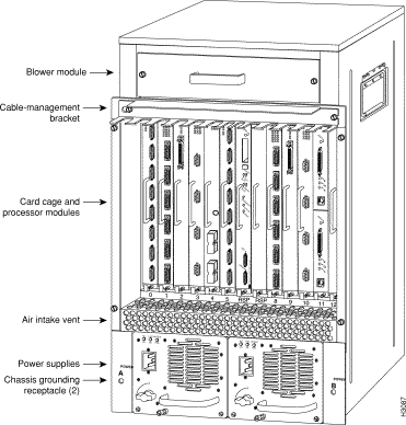
The Cisco 7513 and Cisco 7576 cable-management bracket is mounted above the card cage, on the interface processor end of the chassis. (See Figure 1.) The bracket allows you to route cables away from the interface processors, which keeps this area clear for any future maintenance requirements.
The cable-management bracket attaches to the interface processor end of the chassis just above the card cage and below the blower module. (See Figure 2.) Use the bracket to keep network interface cables untangled and orderly, and to prevent cables from hindering access to interface processors in the interface processor slots.
Install the bracket before connecting network interface cables to the interface processor ports; otherwise, you will probably need to disconnect the cables to install the screws that secure the brackets. Route interface cables through the bracket as you connect them to the interface processor ports. If necessary, wrap cable ties through the holes provided to secure small-gauge cables.
You need the following tools and parts to install the cable-management brackets; the brackets and panhead screws are included with the chassis:
To install the cable-management bracket, follow these steps:
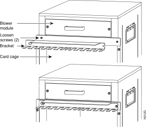
Step 2 Use a flat-blade screwdriver to loosen the two slotted screws approximately 1/8-inch.
Step 3 Place the bracket over the screws (see Figure 2), and slide the bracket to the right.
Step 4 Use a flat-blade screwdriver to tighten the screws.
Step 5 When installing the network interface cables, route the cables up to and through the cable-management bracket. If you are using very thin cables that slip through the bracket openings, insert nylon cable ties through the holes in the bracket and wrap them around the cables to secure them.
Route the excess cable out through either end of the bracket, coil it, and secure it to the rack using nylon cable ties or some other mode of attachment.
It might be necessary to bundle longer cables to avoid tangling them. Do this at the cable-management bracket or at the rack, but leave enough slack in the cables to remove processor modules and change cables as required. Also, do not block the power supply air vents with cables.
This completes the procedure for installing the cable-management bracket.
Cisco Connection Online (CCO) is Cisco Systems' primary, real-time support channel. Maintenance customers and partners can self-register on CCO to obtain additional information and services.
Available 24 hours a day, 7 days a week, CCO provides a wealth of standard and value-added services to Cisco's customers and business partners. CCO services include product information, product documentation, software updates, release notes, technical tips, the Bug Navigator, configuration notes, brochures, descriptions of service offerings, and download access to public and authorized files.
CCO serves a wide variety of users through two interfaces that are updated and enhanced simultaneously: a character-based version and a multimedia version that resides on the World Wide Web (WWW). The character-based CCO supports Zmodem, Kermit, Xmodem, FTP, and Internet e-mail, and it is excellent for quick access to information over lower bandwidths. The WWW version of CCO provides richly formatted documents with photographs, figures, graphics, and video, as well as hyperlinks to related information.
You can access CCO in the following ways:
For a copy of CCO's Frequently Asked Questions (FAQ), contact cco-help@cisco.com. For additional information, contact cco-team@cisco.com.
![]()
![]()
![]()
![]()
![]()
![]()
![]()
![]()
Posted: Fri Apr 27 10:24:24 PDT 2001
All contents are Copyright © 1992--2001 Cisco Systems, Inc. All rights reserved.
Important Notices and Privacy Statement.