|
|

Cisco 7010 Product Numbers: PWR-7010AC= and ACS-7010FAN=
Cisco 7505 Product Numbers: PWR/5-AC= and MAS/5-FAN=
Customer Order Number: DOC-781233=
This document contains instructions for replacing the 600W, AC-input power supply and the fan tray, both of which are available as spare parts for the Cisco 7010 and Cisco 7505 chassis.
The sections in this document include the following:
Following are brief descriptions of the Cisco 7010 and Cisco 7505 routers, the power supply, the fan tray, and the environmental monitoring functions. The power supply and fan tray exchange information with the environmental monitoring software, although each operates independently.
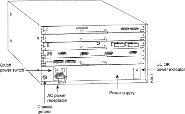
Figure 1 shows the interface processor end of the Cisco 7010 chassis.
In the Cisco 7010, the Route Processor (RP) and Switch Processor (SP) (or the Silicon Switch Processor [SSP]) are required system components and occupy the two top slots. In the Cisco 7505, the Route Switch Processor (RSP1) is a required system component and occupies the top slot.
In both chassis, the remaining interface slots (three in the Cisco 7010 and four in the Cisco 7505) support any combination of available interface types: Ethernet, Token Ring, FDDI, serial, HSSI, and so forth.
The interface processor end of the router also contains the AC power receptacle, the system power on/off switch, and the DC OK power status LED, all of which are part of the power supply but accessible through cutouts in the chassis frame. (See Figure 1.) To the left of the power switch and receptacle cutout is a ground screw that provides a chassis ground connection for ESD equipment or a grounding wire.
The noninterface processor end of the chassis has a removable panel that provides access to the internal components discussed in this publication.Two captive slotted fasteners secure the panel.
Following are the power supply and fan tray product numbers:
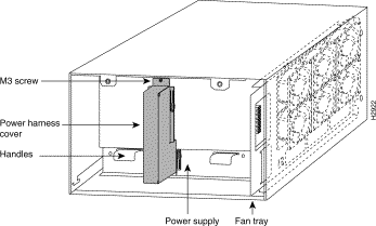
Figure 2 shows the noninterface processor end of the chassis with the cover removed and with the power supply and fan tray in their normal operating positions. The power supply, which rests on the interior chassis floor, operates on AC input and provides DC voltages to the system components. The six individual fans on the fan tray move cooling air through the chassis interior to prevent components from overheating. The backplane contains the data buses for information exchange and distributes power throughout the system.
The Cisco 7010 and Cisco 7505 come equipped with one 600W, AC-input power supply. Table 1 lists the power specifications for the Cisco 7010 and Cisco 7505.
The following sections describe the 600W, AC-input power supply and the fan tray. For descriptions of other system components, refer to the Cisco 7010 Hardware Installation and Maintenance or Cisco 7505 Hardware Installation and Maintenance publications.
Power supply | 600W maximum |
Power dissipation | 600W maximum configuration, 540W typical with maximum configuration |
Heat dissipation | 715W (2440 Btu/hr) |
Input voltage | 100 to 240 VAC, wide input with power factor corrector (PFC) |
AC current rating | 9A maximum at 100 VAC, 4A maximum at 240 VAC at 600W |
Frequency | 50 to 60 Hz |
Power distribution | 70A maximum @ +5 VDC, 15A maximum @ +12 VDC, 3A maximum @ -12 VDC, and 5A maximum @ +24 VDC |
On the noninterface processor end of the power supply, two handles provide grip points for pulling the power supply out of the chassis. (See Figure 2.) Two Phillips screws secure the power supply to the chassis interior. Inside the power supply, two small fans draw cooling air through the power supply interior. The air flows in one side of the supply and out the other side, following the same direction as the chassis cooling air.
The power supply delivers DC power to the internal components through a wiring harness that plugs into a polarized receptacle to the noninterface processor side of the backplane. An aluminum cover shields the harness and power connection. The backplane then distributes the DC voltages to the fan tray, arbiter, and interface processor bus connectors.
The AC power receptacle, power on/off switch, and DC OK status LED are on the opposite (interface processor) end of the power supply, and are accessible through cutouts in the chassis below the processor slots. (See Figure 1.) A modular power cable connects the power supply to the site power source. A cable retention clip on the power supply AC receptacle prevents the cable from being pulled out accidentally. The rocker-type on/off switch turns the power supply on and starts the system. Figure 3 shows a detail view of the interface processor end of the power supply.

The green DC OK LED indicates the status of the power supply and internal DC voltages. The DC OK LED stays on when all of the following conditions are met:
If the AC source power or any of the internal DC voltages exceeds allowable tolerances, the DC OK LED goes off and the system environmental monitor messages indicate the line that is out of tolerance. Because the RP (which uses +5, +12, -12 VDC), and the fan tray (which uses +24 VDC) are both required for operation, the system will probably shut down if any internal voltages reach an out-of-tolerance state.
In addition to the environmental monitoring performed by the system software, the power supply monitors its own temperature and internal voltages. If the supply detects an overvoltage or overtemperature condition, it shuts down to avoid damage to the power supply or other system components.
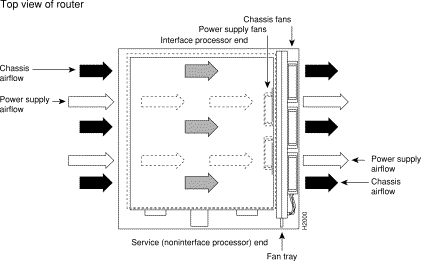
The fan tray comprises six individual axial fans and a printed circuit board (with the control circuits) mounted on a metal plate. (See Figure 2.) The fans draw cooling air through the chassis interior to maintain an acceptable operating temperature for the internal components. The fan tray slides into the right side of the chassis from the noninterface processor end of the router. The fans draw air in through the inlet vents on the opposite side of the chassis, across the processor modules and other internal components, and out through the exhaust vents adjacent to the fan tray. Figure 4 shows a top-down view of the chassis, with the fan tray on the far right, and the airflow path created by the fans. The sides of the chassis must remain unobstructed to ensure adequate airflow and prevent overheating inside the chassis.
A fan control board on the fan tray monitors and controls the operation of the variable-speed fans. The variable-speed feature enables quieter operation by allowing the fans to operate at less than maximum speed when doing so provides adequate cooling air to maintain an acceptable operating temperature for the internal components.
When the internal air temperature is within the normal operating range, the fans operate at the slowest speed, which is 55 percent of the maximum speed. If the temperature inside the chassis exceeds the normal range, the fan control board increases the fan speed to provide additional cooling air to the internal components. If the temperature continues to rise, the fan control board linearly increases the fan speed until the fans reach full speed (100 percent). If the internal temperature exceeds the specified threshold, the system environmental monitor shuts down all internal power to prevent equipment damage from excessive heat.
The fan control board also relays the status of the fans to the system software. All six fans in the array must be operational. If the system detects a failed or failing fan, it displays a warning message on the console screen. If the condition is not corrected within two minutes, the entire system will shut down to protect the internal components against damage from excessive heat. For an example of this display, refer to the following section, "Prerequisites."
Before you begin this installation, review the safety guidelines in this section to avoid injuring yourself or damaging the equipment. This section also provides a list of the tools that you need to perform this replacement.
When working with any electrical equipment, the following guidelines will help to ensure your safety and protect the equipment. This list is not inclusive of all potentially hazardous situations, so be alert.
In addition, use the guidelines that follow when working with any equipment that is connected to telephone wiring or other network cabling:
Opening the chassis and removing the power harness cover exposes the power distribution wiring on the backplane. If the power is not shut down, the high current present on the backplane becomes a hazard. Also, removing the cover compromises the electromagnetic interference (EMI) integrity of the system. Therefore, always make sure that the system power switch is turned off before removing the chassis cover panel or replacing any internal components.
This section lists the tools and equipment you will need to complete these replacement procedures.
Have the following tools on hand so that you can complete the replacement without interruption:
If the chassis is mounted in an equipment rack, ensure that there is at least 1 foot of clearance at the noninterface processor end to remove the power supply or fan tray, both of which you must pull straight out of the chassis.
If a power strip or other equipment obstructs access, you will have to remove the chassis from the rack before replacing the component. Refer to the Cisco 7010 Hardware Installation and Maintenance or Cisco 7505 Hardware Installation and Maintenance publications for the tools you will need and descriptions of the rack mounting hardware.
Electrostatic discharge (ESD) damage, which can occur when electronic boards or components are handled improperly, can result in complete or intermittent failures. The RP, SP, and interface processors each comprise a printed circuit board that is fixed in a metal carrier. EMI shielding, connectors, and a handle are integral components of the carrier. However, the fan control board is a printed circuit board that is not intended to be handled and has no frame or shielding. Handle a processor module or fan tray by the metal frame or carrier only; avoid touching the board (particularly avoid touching any components, traces, or the metal fingers on the edge connector).
Following are guidelines for preventing ESD damage:
 | Caution For safety, periodically check the resistance value of the antistatic strap. The measurement should be between 1 and 10 megohms. |
Figure 2 shows the location of each internal components inside the noninterface processor end of the chassis. To access the power supply and fan tray, you must remove the chassis cover panel and expose the chassis interior. Two captive slotted screws secure the cover panel to the chassis. The fan tray slides into the right side of the chassis (when viewing the chassis from the noninterface processor end). A single M4 Phillips panhead screw anchors a tab on the tray to the chassis frame. An edge connector on the fan control board also snaps into a socket connector on the backplane. To remove the fan tray, you need only remove the M4 screw that anchors the tray to the interior chassis frame. You cannot replace individual fans; if a fan fails, you must replace the whole fan tray assembly. The power supply rests on the floor of the chassis, under the card cage and backplane. Two M3 Phillips screws secure the power supply to the interior chassis frame. The power harness cover shields the power harness, which carries DC voltages from the power supply to a polarized connector on the backplane. Because the power harness cover straddles both the power supply and backplane cover, you must remove it to access the power supply. A tab at the bottom of the power harness cover fits into a slot in the chassis floor; a single Phillips screw secures the top of the power harness cover to the backplane cover. To remove the power supply, you need to disconnect the modular AC power cable, remove the power harness cover, disconnect the power harness from the backplane, and remove the two M4 Phillips screws. The noninterface processor end of the power supply has handles for pulling the supply out of the chassis.
The two captive slotted screws are the only fasteners on the cover panel. (See Figure 5.) Five shallow tabs at the bottom edge of the panel fit into slots at the base of the chassis opening. The tabs act as a pivot point for pulling the top of the panel away from the chassis opening, and as guides to align the panel when replacing it.

 | Warning Before accessing the chassis interior, turn off the system power and unplug the power cable. When the power is on, high current is exposed on the fan tray and backplane. |
Follow these steps to remove and replace the chassis cover panel:
Step 1 On the front of the cover panel, use a 3/16-inch flat-blade screwdriver to loosen the two captive screws. (See Figure 5.)
Step 2 Pull the top of the panel out about three inches, then grasp the sides of the panel and pull it up and away from the chassis.
Step 3 To replace the cover panel, hold the sides of the panel with both hands and tilt the top of the panel back slightly (toward you).
Step 4 Slide the guide tabs into the slots in the bottom edge of the chassis. (See Figure 5.)
Step 5 Using the guides as a pivot point, push the top half of the panel back toward the chassis opening until the panel is flush with the edges of the chassis.
Step 6 Hold the top front of the panel in place, if necessary, while you tighten the two captive slotted screws with a 3/16-inch, flat-blade screwdriver.
This completes the chassis cover panel removal and replacement procedure.
When viewing the chassis from the noninterface processor end, the fan tray is on the far right. (See Figure 2.) A cutout in the front of the tray provides a handle for pulling the tray out of the chassis. An M4 Phillips screw anchors a tab on the lower left side of the tray to the interior chassis frame, just below the right power supply ear. When the fan tray is fully inserted in the chassis, an edge connector on the fan control board snaps into the backplane electrical connector. The bottom of the tray is a metal runner that guides the tray along a metal track on the chassis floor. Also, a bracket on the chassis ceiling helps guide the tray into the chassis.
 | Warning Before accessing the chassis interior, turn off the system power and unplug the power cable. When the power is on, high current is exposed on the fan tray and backplane. |
While referring to Figure 6, follow these steps to replace the fan tray.
Step 1 Follow Steps 1 and 2 in the section "Removing and Replacing the Chassis Cover Panel" to open the chassis.
Step 2 Use a number 2 Phillips screwdriver to remove the M4 Phillips screw from the tab on the lower left side of the fan tray.
Step 3 Grasp the cutout handle in the front of the tray and pull the fan tray straight out of the chassis. After the fan control board connector frees the backplane socket, the fan tray will slide easily along the track and out of the chassis.
Step 4 Place the removed fan tray in an antistatic bag for storage or return to the factory.
Step 5 Hold the new fan tray in the orientation shown in Figure 6. You can hold the handle with either your right or left hand as long as you use both hands to handle the tray. However, when inserting the tray, there is little room between the tray and the right side of the chassis. Keep the tray as straight as possible, or you may have trouble inserting it into the chassis.
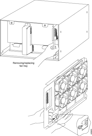
Step 6 Insert the top runner of the fan tray through the notch in the top of the chassis. Continue pushing the tray into the chassis, and ensure that the bottom runner slides into the track on the floor of the chassis. If the tray hangs up, pull it back out a few inches and try pushing it in again. If the runners seem to be catching on the brackets, push the tray slightly toward the left when inserting it again.
Step 7 Slide the tray back into the chassis until the circuit board snaps into the backplane socket.
Step 8 Replace the M4 screw in the tab and tighten it with a number 2 Phillips screwdriver.

Step 9 Follow Steps 3 through 6 in "Removing and Replacing the Chassis Cover Panel" to replace the cover panel.
Step 10 Ensure that the power switch on the interface processor end of the power supply is in the off (O) position, then reconnect the power cable to the AC receptacle (if disconnected).
This completes the fan tray removal and replacement procedure.
Proceed to the section "Checking the Installation" to restart the system and check the installation.
You must remove the power harness cover and disconnect the power harness from the backplane receptacle before you can remove the power supply. A single M3 Phillips screw secures the power harness cover to the backplane cover. To remove the power supply, you will remove the two M4 Phillips screws that secure the power supply ears to the chassis frame.
 | Warning Before accessing the chassis interior, turn off the system power and unplug the power cable to prevent injury. When the power is on, high current is exposed on the fan tray and backplane. |
Follow these steps to remove the power harness cover, power harness, and power supply:
Step 1 Follow Steps 1 and 2 in the section "Removing and Replacing the Chassis Cover Panel" to open the chassis.
Step 2 Use a number 1 Phillips screwdriver to remove the M3 screw that secures the power harness cover to the backplane. (See Figure 8.)
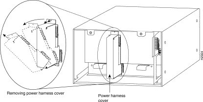
Step 3 Holding the cover with one hand, tilt the top of the cover back toward you, then pull it up slightly so that the tab clears the slot in the chassis floor.
Step 4 When the tab clears the slot, pull the cover straight back off the harness and out of the chassis.
Step 5 Disconnect the power harness plug from the backplane receptacle by pulling the polarized plug out of the receptacle; do not pull on the wires. (See Figure 9a.)
Step 6 Use a number 2 Phillips screwdriver to remove the two M4 Phillips panhead screws that secure the power supply ears (one on each side of the power supply) to the chassis frame. (See Figure 9a.)
Step 7 Using both hands, grasp both of the power supply handles and pull the power supply about halfway out of the bay (see Figure 9b), then grab the sides of the supply and pull it out of the chassis. (See Figure 9c.)
This completes the power supply removal procedure.
Proceed to the next section to install the new power supply and replace the power harness cover.
Follow these steps to remove the power harness cover and power supply:
Step 1 On the interface processor end of the power supply, remove the cable retention clip from the AC receptacle (or tape it up out of the way); it can catch on the floor of the chassis during the installation. To remove the clip, pinch the sides together until they clear the jackscrews. (See Figure 3.)
Step 2 Hold the supply as shown in Figure 9c and slide it into the bottom of the chassis. Use the handles to push the supply all the way into the chassis until the ears on both sides are flush against the chassis frame.
Step 3 Use a number 2 Phillips screwdriver to replace the two M4 Phillips panhead screws to secure the two power supply ears to the chassis frame.
Step 4 Reconnect the power harness plug to the backplane receptacle. (See Figure 9a.) The harness plug and backplane receptacle are polarized with notches at the top of both guide tabs (top and bottom) on the plug. Ensure that the plug is fully seated in the receptacle.
Step 5 To replace the power harness cover, hold the cover with one hand, with the tab on the bottom and the open side facing away from you. Tilt the top of the panel back slightly (toward you) and insert the tab on the bottom of the cover into the slot in the chassis floor. (See Figure 8.)
Step 6 While pushing the cover downward slightly to keep the bottom tab in the slot, push the top of the cover back over the harness wires until the sides are flush against the backplane cover. Ensure that all of the harness wires are under the cover.
Step 7 Insert the M3 screw through the top of the harness cover and use a number 1 Phillips screwdriver to tighten it.
Step 8 Follow Steps 3 through 6 in the section "Removing and Replacing the Chassis Cover Panel" to replace the chassis cover panel.
Step 9 Ensure that the power switch on the interface processor end of the power supply is in the off (O) position, then reconnect the power cable to the AC receptacle (if disconnected).
Step 10 Replace the cable retention clip between the two jackscrews on the power receptacle at the interface processor end. Squeeze the sides of the clip together, insert the ends between the jackscrews, then release the clip and guide the ends into the holes in the jackscrews.
This completes the new power supply installation.
Proceed to the section "Checking the Installation" to restart the system and check the installation.

 | Warning Disconnect the power harness by pulling on the connector plug; do not pull or tug on the harness wires. |
To complete the installation, perform the following steps to verify that the new component is installed correctly and functioning properly. These steps will also help you verify that all the active components that you removed or disconnected as part of this replacement procedure are returned to their previous state, when all router components (except the fan tray or power supply you replaced) were operating properly.
Step 1 Turn the system power switch back on. The DC OK LED should go on immediately. If if does, proceed to the next step. If it does not, do the following:
Step 2 About 10 seconds after you turn on the power, verify that the normal LED on the RP or RSP1 goes on, which indicates that the system software booted successfully. If it does go on, proceed to the next step. If it does not go on, do the following:
Step 3 After the system initializes, use the various show environment commands to display the status of the power supply and fan tray, and ensure that they are operating within normal specifications. (For descriptions and examples of these commands, refer to the section "Prerequisites".)
This completes the fan tray and power supply replacement procedures for the Cisco 7010 and Cisco 7505.
Cisco Information Online (CIO) is Cisco Systems' primary, real-time support channel. Maintenance customers and partners can self-register on CIO to obtain additional content and services.
Available 24 hours a day, 7 days a week, CIO provides a wealth of standard and value-added services to Cisco's customers and business partners. CIO services include product information, software updates, release notes, technical tips, the Bug Navigator, configuration notes, brochures, descriptions of service offerings, and download access to public and authorized files.
CIO serves a wide variety of users through two interfaces that are updated and enhanced simultaneously—a character-based version and a multimedia version that resides on the World Wide Web (WWW). The character-based CIO (called "CIO Classic") supports Zmodem, Kermit, Xmodem, FTP, Internet e-mail, and fax download options, and is excellent for quick access to information over lower bandwidths. The WWW version of CIO provides richly formatted documents with photographs, figures, graphics, and video, as well as hyperlinks to related information.
You can access CIO in the following ways:
http://www.cisco.com cio.cisco.com For a copy of CIO's Frequently Asked Questions (FAQ), contact cio-help@cisco.com. For additional information, contact cio-team@cisco.com.
tac@cisco.com. To obtain general information about Cisco Systems, Cisco products, or upgrades, contact 800 553-6387, 408 526-7208, or cs-rep@cisco.com.

![]()
![]()
![]()
![]()
![]()
![]()
![]()
![]()
Posted: Fri Nov 8 16:30:00 PST 2002
All contents are Copyright © 1992--2002 Cisco Systems, Inc. All rights reserved.
Important Notices and Privacy Statement.