|
|

Table Of Contents
RSP4+ Bootflash Memory Upgrade to 16MB Installation and Configuration Guide
Software and Bootflash Prerequisites
Confirming the Bootflash Memory Size
Loading and Configuring the Bootflash Image
Obtaining Technical Assistance
RSP4+ Bootflash Memory Upgrade to 16MB Installation and Configuration Guide
Product Numbers: MEM-16F-RSP4+=
Customer Order Number: DOC-7812288=
Introduction
An 8 MB bootflash image is supplied with the RSP4+, RSP4, RSP2, RSP1 and RSP7000 on the Cisco 7500 series routers. This image is insufficient to store newer, larger Cisco IOS Releases, such as 12.1(4.4)T2 and 12.1(5)T, and future releases on the RSP4+. Use the instructions in this document to upgrade to a 16-MB bootflash. Alternatively, you can use Cisco IOS Release 12.0(13)S rsp-boot-mz image or other image, which is less than 7.7 MB in size. Contact the Technical Assistance Center (see Technical Assistance Center) for more information on this latter alternative.
Note: The RSP8 has 16 MB of Flash memory and does not encounter this problem.
Objectives
The purpose of this document is to explain how to perform the following procedures:
•
Remove the 8-MB SIMM and install a 16-MB SIMM
•
Contents
This document includes the following sections:
•
•
•
•
Related Documentation
Your router and the Cisco IOS software running on it contain extensive features and functionality, which are documented in the following resources:
•
For configuration information and support, refer to the modular configuration and modular command reference publications in the Cisco IOS software configuration documentation set that corresponds to the software release installed on your Cisco hardware.
Note
•
For hardware installation and maintenance information on the Cisco 7500 series routers, refer to the Cisco 7500 Installation and Configuration Guide that shipped with your router.
•
–
–
•
Installation Requirements
Before upgrading the bootflash SIMM, pay attention to the following sections:
•
Software and Bootflash Prerequisites
The minimum software and bootflash requirements are listed in Table 1. The Cisco IOS releases listed in Table 1 apply to all Cisco 7500 series routers except for the Cisco 7576, which requires Cisco IOS Release 11.1(22) CC or a later release of 11.1 CC.
Table 1 RSP4+ Minimum Software and Bootflash Memory Requirements
Minimum Bootflash Memory
Cisco IOS Release 11.1(8)CA
Cisco IOS Release 11.1(8)CA or later release of Cisco IOS Release 11.1 CA
8 MB
Cisco IOS Release 11.1(17)CC
Cisco IOS Release 11.1(17)CC or later release of Cisco IOS Release 11.1 CC
8 MB
Cisco IOS Release 11.2(6)P
Cisco IOS Release 11.2(6)P or later release of Cisco IOS Release 11.2 P
8 MB
Cisco IOS Release 11.3(1)T
Cisco IOS Release 11.3(1)T or later release of Cisco IOS Release 11.3 T
8 MB
Cisco IOS Release 11.3(1)
Cisco IOS Release 11.3(1) or later release of Cisco IOS Release 11.3
8 MB
Cisco IOS Release 12.0(1)T
Cisco IOS Release 12.0(1)T or later release of Cisco IOS Release 12.0T
8 MB
Cisco IOS Release 12.0(1)
Cisco IOS Release 12.0(1) or later release of Cisco IOS Release 12.0
8 MB
Cisco IOS Release 12.0(2)XE3
Cisco IOS Release 12.0(2)XE3 or later release of Cisco IOS Release 12.0 XE3
8 MB
Cisco IOS Release 12.0(4)XE1
Cisco IOS Release 12.0(4)XE1 or later release of Cisco IOS Release 12.0 XE1
8 MB
Cisco IOS Release 12.0(5)S
Cisco IOS Release 12.0(5)S or later release of Cisco IOS Release 12.0 S
8 MB
Cisco IOS Release 12.1(1)E
Cisco IOS Release 12.1(1)E or later release of Cisco IOS Release 12.1 E
8 MB
Cisco IOS Release 12.1(1)
Cisco IOS Release 12.1(1) or later release of Cisco IOS Release 12.1
8 MB
Cisco IOS Release 12.1(5)T
Cisco IOS Release 12.1(5)T or later release of Cisco IOS Release 12.1 T
16 MB
1 Applies to all platforms that support the RSP4+ except Cisco 7576, which requires Cisco IOS Release 11.1(22)CC or a later release of 11.1 CC.
Tools and Parts Required
You need the following tools and parts to install or upgrade the bootflash SIMM:
•
•
•
If you need additional equipment, contact a service representative for ordering information.
Safety Guidelines
Following are safety guidelines that you should follow when working with any equipment that connects to electrical power or telephone wiring.
Safety Warnings
Safety warnings appear throughout this publication in procedures that, if performed incorrectly, may harm you. A warning symbol precedes each warning statement.
Installation Warning
Electrical Equipment Guidelines
Follow these basic guidelines when working with any electrical equipment:
•
•
•
•
•
•
Preventing Electrostatic Discharge Damage
Electrostatic discharge (ESD) damage, which can occur when electronic cards or components are improperly handled, results in complete or intermittent failures.
Use the following guidelines for preventing ESD damage:
•
•
•
•
•
•
•
•
Caution
Wrist Strap Warning
Overview
Bootflash is a single inline memory module (SIMM) with a bootloader image that allows the router to access the Cisco IOS image when powering up or initializing the system. Bootloader images can be downloaded over the network, or from a local server. Refer to Table 1 for a list of IOS images that require a 16MB bootflash.
In this document, you will perform the following steps to upgrade the bootflash to 16MB:
•
•
•
•
•
•
Confirming the Bootflash Memory Size
To check the bootflash memory size on your RSP4+, use the show version command. The following example indicates that the bootflash memory size is insufficient for Cisco IOS Release 12.1(4.4)T2 and 12.1(5)T, and later releases.
Router# show versionCisco Internetwork Operating System SoftwareIOS (tm) 7500 Software (C7200-J-M), Released Version 12.0(2)Copyright (c) 1986-1998 by cisco Systems, Inc.20480K bytes of Flash PCMCIA card at slot 0 (Sector size 128K).8192K bytes of Flash internal SIMM (Sector size 256K)Removing the RSP4+
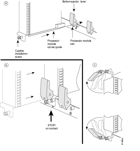
The first step in upgrading the bootflash is to remove the RSP4+ from the Cisco 7500 series router.
Step 1
Step 2
Step 3
Step 4
Caution
Step 5
Step 6
Step 7
Figure 1 Ejector Levers and Captive Installation Screws on the RSP4+—Vertical Orientation Shown
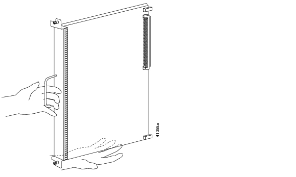
Figure 2 Handling the RSP4+ During Removal and Installation
This completes the RSP4+ removal procedure.
Removing the SIMM
After removing the RSP4+ from the Cisco 7500 series router, remove the 8-MB SIMM, using the following procedure.
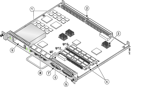
Step 1
Figure 3 Location of SIMM on the RSP4+
Step 2
Step 3
Figure 4 Releasing the SIMM Spring Clips
Step 4
Figure 5 Handling a SIMM
Caution
Step 5
This completes the SIMM removal procedure. Proceed to the next section to install the new SIMM.
Installing the SIMM
After removing the 8-MB SIMM, use the following procedure to install the 16-MB SIMM.
Step 1
Step 2
Step 3
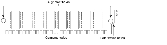
Note
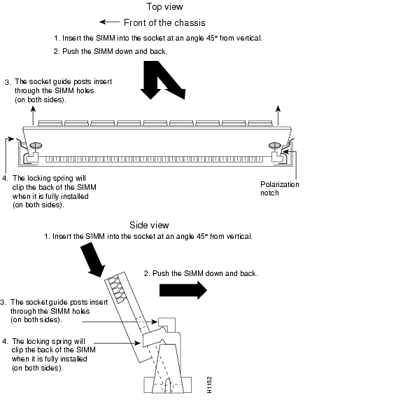
Figure 6 SIMM Polarization Notch
Step 4
Note
Step 5
Figure 7 Inserting Vertically-Loaded SIMMS
Step 6
This completes the new SIMM installation procedure.
Installing the RSP4+
Follow the steps below to reinstall the RSP4+ that was removed.
Step 1
Caution
Step 2
Step 3
Caution
Step 4
Step 5
Step 6
This completes theRSP4+ installation procedure.
Loading and Configuring the Bootflash Image
Using the steps in this procedure, you will:
•
•
•
•
•
•
•
•
•
Step 1
Step 2
Router> enPassword:Router#Step 3
Router#sh verCisco Internetwork Operating System SoftwareIOS (tm) RSP Software (RSP-JSV56I-M), Version 12.1(3)T, RELEASE SOFTWARE (fc1)Copyright (c) 1986-2000 by cisco Systems, Inc.Compiled Wed 19-Jul-00 22:18 by ccaiImage text-base: 0x60010968, data-base: 0x618D2000ROM: System Bootstrap, Version 12.0(10r)S1, RELEASE SOFTWARE (fc1)BOOTFLASH: RSP Software (RSP-BOOT-M), Version 12.0(8)S, EARLY DEPLOYMENT RELEAS)doc-7507 uptime is 12 weeks, 3 days, 21 hours, 29 minutesSystem returned to ROM by bus error at PC 0x60330F20, address 0x6229System image file is "slot0:rsp-jsv56i-mz.121-3.T"cisco RSP8 (R7000) processor with 131072K/8216K bytes of memory.R7000 CPU at 250Mhz, Implementation 39, Rev 1.0, 256KB L2, 2048KB L3 CacheLast reset from power-onG.703/E1 software, Version 1.0.G.703/JT2 software, Version 1.0.X.25 software, Version 3.0.0.SuperLAT software (copyright 1990 by Meridian Technology Corp).Bridging software.TN3270 Emulation software.Chassis Interface.1 VIP2 controller (1 FastEthernet).1 FastEthernet/IEEE 802.3 interface(s)2043K bytes of non-volatile configuration memory.20480K bytes of Flash PCMCIA card at slot 0 (Sector size 128K).16384K bytes of Flash internal SIMM (Sector size 256K).No slave installed in slot 3.Configuration register is 0x102Step 4
Router#format bootflash:Format operation may take a while. Continue? [confirm]Format operation will destroy all data in "bootflash:". Continue? [confirm]Formatting sector 1Format of bootflash completeRouter#Step 5
Router# copy tftp:rsp-boot-mz.121-5.T1 bootflash:rsp-boot-mz.121-5.T120575008 bytes available on device slot0, proceed? [confirm]Address or name of remote host [1.1.1.1]?Loading new.image from 1.1.1.1 (via Ethernet1/0):!!!!!!!!!!!!!!!!!!!!!!!!!!!!!!!!!!!!!!!!!!!!!!!!!!!!!!!!!!!!!!!!!!!!!!!!!!!!!!!!!!!!!!!!!!!!!!!!!!!!!!!!!!!!!!!!!!!!!!!!!!!!!!!!!!!!!!!!!!!!!!!!!!!!!!!!!!!!!!!!!!!!!!!!!!!!!!!!!!!!!!!!!!!!!!!!!!!!!!!!!!!!!!!!!!!!!!!!!!!!!!!!!!!!!!!!!!!!!!!!!!!!!!!!!!!!!!!!!!!!!!!!!!!!!!!!!!!!!!!!!!!!!!!!!!!!!!!!!!!!!!!!!!!!!!!!!!!!!!!!!!!!!!!!!!!!!!!!!!!!!!!!!!!!!!!!!!!!!!!!!!!!!!!!!!!!!!!!!!!!!!!!!!!!!!!!!!!!!!!!!!!!!!!!!!!!!!!!!!!!!!!!!!!!!!!!!!!!!!!!!!!!!!!!!!!!!!!!!!!!!!!!!!!!!!!!!!!![OK - 7799951/15599616 bytes]CCCCCCCCCCCCCCCCCCCCCCCCCCCCCCCCCCCCCCCCCCCCCCCCCCCCCCCCCCCCCCCCCCCCCCCCCCCCCCCCCCCCCCCCCCCCCCCCCCCCCCCCCCCCCCCCCCCCCCCCCCCCCCCCCCCCCCCCCCCCCCCCCCCCCCCCCCCCCCCCCCCCCCCCCCCCCCCCCCCCCCCCCCCCCCCCCCCCCCCCCCCCCCCCCCCCCCCCCCCCCCCCCCCCCCCCCCRouter#
Note
Step 6
Router# dir bootflash:Directory of bootflash:/1 -rw- 5090824 Jan 01 2000 00:02:28 rsp-boot-mz.121-5.T17602176 bytes total (2511224 bytes free)Router#Step 7
Router# configure terminalEnter configuration commands, one per line. End with CNTL/Z.Step 8
Router(config)# boot bootldr bootflash:rsp-boot-mz.121-5.T1The bootloader command is automatically added to your running configuration.
Step 9
Step 10
Router#Router# copy running-config startup-configThe new bootloader image is saved in the startup-config.
Step 11
Router#sh bootvBOOT variable =CONFIG_FILE variable = bootflash:startup-configBOOTLDR variable = bootflash:rsp-boot-mz.121-5.T1Configuration register is 0x0This completes the procedure for loading and configuring the boot image.
Obtaining Documentation
The following sections provide sources for obtaining documentation from Cisco Systems.
World Wide Web
You can access the most current Cisco documentation on the World Wide Web at the following sites:
•
•
•
Documentation CD-ROM
Cisco documentation and additional literature are available in a CD-ROM package, which ships with your product. The Documentation CD-ROM is updated monthly and may be more current than printed documentation. The CD-ROM package is available as a single unit or as an annual subscription.
Ordering Documentation
Cisco documentation is available in the following ways:
•
http://www.cisco.com/cgi-bin/order/order_root.pl
•
http://www.cisco.com/go/subscription
•
Documentation Feedback
If you are reading Cisco product documentation on the World Wide Web, you can submit technical comments electronically. Click Feedback in the toolbar and select Documentation. After you complete the form, click Submit to send it to Cisco.
You can e-mail your comments to bug-doc@cisco.com.
To submit your comments by mail, for your convenience many documents contain a response card behind the front cover. Otherwise, you can mail your comments to the following address:
Cisco Systems, Inc.
Document Resource Connection
170 West Tasman Drive
San Jose, CA 95134-9883We appreciate your comments.
Obtaining Technical Assistance
Cisco provides Cisco.com as a starting point for all technical assistance. Customers and partners can obtain documentation, troubleshooting tips, and sample configurations from online tools. For Cisco.com registered users, additional troubleshooting tools are available from the TAC website.
Cisco.com
Cisco.com is the foundation of a suite of interactive, networked services that provides immediate, open access to Cisco information and resources at anytime, from anywhere in the world. This highly integrated Internet application is a powerful, easy-to-use tool for doing business with Cisco.
Cisco.com provides a broad range of features and services to help customers and partners streamline business processes and improve productivity. Through Cisco.com, you can find information about Cisco and our networking solutions, services, and programs. In addition, you can resolve technical issues with online technical support, download and test software packages, and order Cisco learning materials and merchandise. Valuable online skill assessment, training, and certification programs are also available.
Customers and partners can self-register on Cisco.com to obtain additional personalized information and services. Registered users can order products, check on the status of an order, access technical support, and view benefits specific to their relationships with Cisco.
To access Cisco.com, go to the following website:
http://www.cisco.com
Technical Assistance Center
The Cisco TAC website is available to all customers who need technical assistance with a Cisco product or technology that is under warranty or covered by a maintenance contract.
Contacting TAC by Using the Cisco TAC Website
If you have a priority level 3 (P3) or priority level 4 (P4) problem, contact TAC by going to the TAC website:
http://www.cisco.com/tac
P3 and P4 level problems are defined as follows:
•
•
In each of the above cases, use the Cisco TAC website to quickly find answers to your questions.
To register for Cisco.com, go to the following website:
http://www.cisco.com/register/
If you cannot resolve your technical issue by using the TAC online resources, Cisco.com registered users can open a case online by using the TAC Case Open tool at the following website:
http://www.cisco.com/tac/caseopen
Contacting TAC by Telephone
If you have a priority level 1(P1) or priority level 2 (P2) problem, contact TAC by telephone and immediately open a case. To obtain a directory of toll-free numbers for your country, go to the following website:
http://www.cisco.com/warp/public/687/Directory/DirTAC.shtml
P1 and P2 level problems are defined as follows:
•
•
![]()
![]()
![]()
![]()
![]()
![]()
![]()
![]()
Posted: Tue Apr 11 13:30:05 PDT 2006
All contents are Copyright © 1992--2006 Cisco Systems, Inc. All rights reserved.
Important Notices and Privacy Statement.