|
|

Table Of Contents
Configuring Ethernet SPAs on Cisco IOS XR Software
Specifying the Interface Address
Configuring a Basic Ethernet Interface
Verifying the Interface Configuration
Configuring an Ethernet Interface Example
Configuring MAC Accounting Example
Configuring Ethernet SPAs on Cisco IOS XR Software
This chapter provides information about configuring Ethernet SPAs on the Cisco XR 12000 Series Router running Cisco IOS XR software. It includes the following sections:
•
Verifying the Interface Configuration
For information about managing your system images and configuration files, refer to the Cisco IOS XR Getting Started Guide, Release 3.2 and the Cisco IOS XR Commands Master List, Release 3.2 publications.
For more information about the commands used in this chapter, see Chapter 10, "Command Reference" which documents new and modified commands and the Cisco IOS XR Interface and Hardware Component Command Reference, Release 3.0. For more information about accessing these publications, see the "Related Documentation" section in the "Preface".
Configuration Tasks
This section describes how to configure the Gigabit Ethernet SPAs. It includes the following topics:
•
•
•
Required Configuration Steps
This section lists the required configuration steps to configure the Gigabit Ethernet SPAs. Some of the required configuration commands have default values that might be appropriate for your network. If the default value is correct for your network, then you do not need to configure the command. These commands are indicated by "(Optional)" in the purpose column.
Note
SUMMARY STEPS
1.
2.
3.
4.
5.
or
ipv6 address ipv6-prefix/prefix-length6.
7.
8.
9.
10.
11.
12.
or
commitDETAILED STEPS
Specifying the Interface Address
SPAs on Cisco XR 12000 Series Routers running Cisco IOS XR software use an addressing format that specifies the physical location of the SIP, SPA, and interface. The interface address format is rack/slot/subslot/port:
•
•
•
•
–
–
–
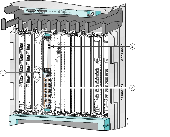
Figure 4-1 shows the slot, subslot, and interface port locations of the 1-Port 10-Gigabit Ethernet SPA and 10-Port Gigabit Ethernet SPA installed in the SIP located in slot 3.
Figure 4-1 Slot, Subslot, and Port Locations on the Cisco 12000 SIP-600
Router slot number 3
SPA subslot 1 with ports 0/3/1/0 to 0/3/1/9
SPA subslot number 0 with port 0/3/0/0
For more information about the installation of cards on the Cisco XR 12000 Series Router, refer to the Cisco 12000 Series Router SIP and SPA Hardware Installation Guide.
Configuring a Basic Ethernet Interface
To configure Gigabit Ethernet interfaces you need to understand the following concepts:
•
•
•
•
•
•
Ethernet Technology Overview
Ethernet was developed in the mid-1970s as a 10-Mbps networking protocol operating over a heavy coax cable.
Today, although many networks have migrated to Fast Ethernet (100 Mbps), Gigabit Ethernet (1000 Mbps), and 10-Gigabit Ethernet (10 Gbps), 10-Mbps Ethernet is still in widespread use and forms the basis of most networks.
Ethernet is defined by the IEEE 802.3 international standard. It enables the connection of up to 1024 nodes over coax, twisted-pair, or fiber-optic cable.
Default Configuration Values
When an interface is enabled on an Ethernet SPA and associated SIP, the following default interface configuration parameters are present. See Table 4-1.
Note
Gigabit Ethernet Protocol Standards Overview
IEEE 802.3ab 1000BASE-T Gigabit Ethernet
The IEEE 802.3ab protocol standards, or Gigabit Ethernet over copper (also known as 1000BaseT) is an extension of the existing Fast Ethernet standard. It specifies Gigabit Ethernet operation over the Category 5e/6 cabling systems already installed, making it a highly cost-effective solution. As a result, most copper-based environments that run Fast Ethernet can also run Gigabit Ethernet over the existing network infrastructure in order to dramatically boost network performance for demanding applications.
IEEE 802.3z 1000 Mbps Gigabit Ethernet
Gigabit Ethernet builds on top of the Ethernet protocol, but increases speed tenfold over Fast Ethernet to 1000 Mbps, or 1 Gbps. Gigabit Ethernet allows Ethernet to scale from 10 or 100 Mbps at the desktop to 100 Mbps up to 1000 Mbps in the data center. Gigabit Ethernet conforms to the IEEE 802.3z protocol standard.
By leveraging the current Ethernet standard and the installed base of Ethernet and Fast Ethernet switches and routers, network managers do not need to retrain and relearn a new technology in order to provide support for Gigabit Ethernet.
IEEE 802.3ae 10 Gbps Ethernet
Under the International Standards Organization's Open Systems Interconnection (OSI) model, Ethernet is fundamentally a Layer 2 protocol. 10-Gigabit Ethernet uses the IEEE 802.3 Ethernet MAC protocol, the IEEE 802.3 Ethernet frame format, and the minimum and maximum IEEE 802.3 frame size. 10 Gbps Ethernet conforms to the IEEE 802.3ae protocol standards.
Just as 1000BASE-X and 1000BASE-T (Gigabit Ethernet) remained true to the Ethernet model, 10-Gigabit Ethernet continues the natural evolution of Ethernet in speed and distance. Because it is a full-duplex only and fiber-only technology, it does not need the carrier-sensing multiple-access with collision detection (CSMA/CD) protocol that defines slower, half-duplex Ethernet technologies. In every other respect, 10-Gigabit Ethernet remains true to the original Ethernet model.
MAC Accounting
The MAC address accounting feature provides accounting information for IP traffic based on the source and destination MAC addresses on LAN interfaces. This feature calculates the total packet and byte counts for a LAN interface that receives or sends IP packets to or from a unique MAC address. It also records a time stamp for the last packet received or sent.
Ethernet MTU
A maximum transmission unit (MTU) is the largest size packet or frame, specified in octets (eight-bit bytes), that can be sent in a packet- or frame-based network such as the Internet. The Internet's TCP uses the MTU to determine the maximum size of each packet in any transmission. Too large an MTU size may mean retransmissions if the packet encounters a router that can't handle the large packet. Too small an MTU size means relatively more header overhead and more acknowledgements that have to be sent and handled. Most computer operating systems provide a default MTU value that is suitable for most users. The default value is 1514 for standard frames and 1518 for 802.1Q tagged frames. These numbers exclude the 4 byte frame check sequence (FCS).
Flow Control on Ethernet Interfaces
The flow control used on Gigabit Ethernet interfaces consists of periodically sending flow control pause frames. It is fundamentally different from the usual full- and half-duplex flow control used on standard management interfaces. Flow control can be activated for either ingress traffic, egress traffic or bi-directional traffic. Flow control by default is not activated on SPA Gigabit Ethernet interfaces.
Some hardware has restrictions on how flow-control can be configured. If you attempt to configure a method of flow-control that is not supported, an error is returned at configuration verification. The current operational flow control settings can be displayed using the show interfaces command.
MAC Address
A MAC address is a 6-byte-long hardware address that uniquely identifies each node of a network.
802.1Q VLAN
A VLAN is a group of devices on one or more LANs that are configured so that they can communicate as if they were attached to the same wire, when in fact they are located on a number of different LAN segments. Because VLANs are based on logical instead of physical connections, it is very flexible for user and host management, bandwidth allocation, and resource optimization.
The IEEE's 802.1Q protocol standard addresses the problem of breaking large networks into smaller parts so broadcast and multicast traffic does not consume more bandwidth than necessary. The standard also helps provide a higher level of security between segments of internal networks.
The 802.1Q specification establishes a standard method for inserting VLAN membership information into Ethernet frames.
VRRP
The Virtual Router Redundancy Protocol (VRRP) eliminates the single point of failure inherent in the static default routed environment. VRRP specifies an election protocol that dynamically assigns responsibility for a virtual router to one of the VPN concentrators on a LAN. The VRRP VPN concentrator controlling the IP addresses associated with a virtual router is called the Master, and forwards packets sent to those IP addresses. When the master becomes unavailable, a backup VPN concentrator takes the place of the master.
For more information on VRRP, refer to the "Implementing VRRP on Cisco IOS XR Software" module of the Cisco IOS XR IP Addresses and Services Configuration Guide.
HSRP
Hot Standby Routing Protocol (HSRP) is a proprietary protocol from Cisco. HSRP is a routing protocol that provides backup to a router in the event of failure. Several routers are connected to the same segment of an Ethernet, FDDI, or token-ring network and work together to present the appearance of a single virtual router on the LAN. The routers share the same IP and MAC addresses and therefore, in the event of failure of one router, the hosts on the LAN are able to continue forwarding packets to a consistent IP and MAC address. The transfer of routing responsibilities from one device to another is transparent to the user.
HSRP is designed to support non disruptive failover of IP traffic in certain circumstances and to allow hosts to appear to use a single router and to maintain connectivity even if the actual first hop router they are using fails. In other words, HSRP protects against the failure of the first hop router when the source host cannot learn the IP address of the first hop router dynamically. Multiple routers participate in HSRP and in concert create the illusion of a single virtual router. HSRP ensures that one and only one of the routers is forwarding packets on behalf of the virtual router. End hosts forward their packets to the virtual router.
The router forwarding packets is known as the active router. A standby router is selected to replace the active router should it fail. HSRP provides a mechanism for determining active and standby routers, using the IP addresses on the participating routers. If an active router fails a standby router can take over without a major interruption in the host's connectivity.
HSRP runs on top of User Datagram Protocol (UDP), and uses port number 1985. Routers use their actual IP address as the source address for protocol packets, not the virtual IP address, so that the HSRP routers can identify each other.
For more information on HSRP, refer to the "Implementing HSRP on Cisco IOS XR Software" module of the Cisco IOS XR IP Addresses and Services Configuration Guide.
Verifying the Interface Configuration
Use the following task to display your router configuration settings.
SUMMARY STEPS
1.
2.
DETAILED STEPS
Configuration Examples
This section contains the following examples:
•
•
Configuring an Ethernet Interface Example
The following example indicates how to configure an interface for the Gigabit Ethernet SPA:
RP/0/0/CPU0:Router# configureRP/0/0/CPU0:Router(config)# interface gigabitethernet 0/2/0/0RP/0/0/CPU0:Router(config-if)# ipv4 address 172.18.189.38 255.255.255.224RP/0/0/CPU0:router(config-if)# flow-control ingressRP/0/0/CPU0:Router(config-if)# mtu 1448RP/0/0/CPU0:Router(config-if)# mac-address 0000.0c00.e8bbRP/0/0/CPU0:Router(config-if)# no shutdownRP/0/0/CPU0:Router(config-if)# endUncommitted changes found, commit them before exiting(yes/no/cancel)? [cancel]:yesLC/0/2/CPU0:Feb 13 03:47:44.622 : ifmgr[137]: %PKT_INFRA-LINK-3-UPDOWN : Interface GigabitEthernet0/2/0/0, changed state to UpRP/0/0/CPU0:Feb 13 03:47:45.010 : config[65730]: %MGBL-LIBTARCFG-6-COMMIT : Configuration committed by user 'xxx'. Use 'show commit changes 1000012264' to view the changes.RP/0/0/CPU0:Feb 13 03:47:45.091 : config[65730]: %MGBL-SYS-5-CONFIG_I : Configured from console by xxxRP/0/0/CPU0:Router# show interfaces gigabitethernet 0/2/0/0GigabitEthernet0/2/0/0 is up, line protocol is upHardware is GigabitEthernet, address is 0000.0c00.e8bb (bia 0000.0c00.e8bb)Internet address is 172.18.189.38/27MTU 1448 bytes, BW 1000000 Kbitreliability 255/255, txload 1/255, rxload 1/255Encapsulation ARPA,Full-duplex, 1000Mb/s, SX, link type is force-upoutput flow control is off, input flow control is onloopback not setLast clearing of "show interface" counters never5 minute input rate 0 bits/sec, 0 packets/sec5 minute output rate 0 bits/sec, 0 packets/sec0 packets input, 0 bytes, 0 total input drops0 drops for unrecognized upper-level protocolReceived 0 broadcast packets, 0 multicast packets0 runts, 0 giants, 0 throttles, 0 parity0 input errors, 0 CRC, 0 frame, 0 overrun, 0 ignored, 0 abort1 packets output, 46 bytes, 0 total output dropsOutput 0 broadcast packets, 0 multicast packets0 output errors, 0 underruns, 0 applique, 0 resets0 output buffer failures, 0 output buffers swapped out0 carrier transitionsConfiguring MAC Accounting Example
The following example indicates how to configure MAC-accounting on an Ethernet interface:
RP/0/0/CPU0:Router# configRP/0/0/CPU0:Router(config)# gigabitethernet 0/0/0/2RP/0/0/CPU0:Router(config-if)# ipv4 address 172.18.189.38 255.255.255.224RP/0/0/CPU0:Router(config-if)# mac-accounting egressRP/0/0/CPU0:Router(config-if)# commitRP/0/0/CPU0Sep 19 20:21:11.330 : config[65726]: %LIBTARCFG-6-COMMIT : Configuration committed by user 'unknown'. Use 'show commit changes 1000003461' to view the changes.RP/0/0/CPU0:Router(config-if)# exitRP/0/0/CPU0:Router(config)# exit
![]()
![]()
![]()
![]()
![]()
![]()
![]()
![]()
Posted: Mon Jan 9 21:05:28 PST 2006
All contents are Copyright © 1992--2006 Cisco Systems, Inc. All rights reserved.
Important Notices and Privacy Statement.