cc/td/doc/product/core/cis12000/linecard/lc_spa/spa_hw
hometocprevnextglossaryfeedbacksearchhelp
PDF

Table Of Contents

Installing and Removing a SPA Interface Processor

Handling SIPs

Removing and Installing a SIP

Guidelines for SIP Removal and Installation

Removing a SIP

Installing a SIP


Installing and Removing a SPA Interface Processor


Release 12.0(32)SY1, OL-8831-01, Rev. G6, July 19, 2007

This chapter describes how to install or remove SIPs on the Cisco 12000 series router. This chapter contains the following sections:

Handling SIPs

Removing and Installing a SIP

Guidelines for SIP Removal and Installation

Removing a SIP

Installing a SIP

Handling SIPs

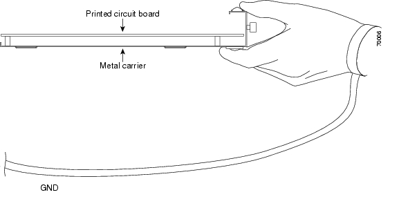
Each SIP circuit board is mounted to a metal carrier and is sensitive to electrostatic discharge (ESD) damage. Before you begin installation, read "Preparing to Install a SPA Interface Processor or a Shared Port Adapter" for a list of parts and tools required for installation.


Caution Always handle the SIP by the carrier edges and handle; never touch the SIP components or connector pins. (See Figure 4-1.)

When a slot is not in use, a blank filler plate must fill the empty slot to allow the router to conform to electromagnetic interference (EMI) emissions requirements and to allow proper airflow across the installed modules. If you plan to install a SIP in a slot that is not in use, you must first remove the blank filler plate.

Figure 4-1 Handling a SIP

Removing and Installing a SIP

The following sections describe the procedures for removing and installing SIPs:

Guidelines for SIP Removal and Installation

Removing a SIP

Installing a SIP


Note Some of the procedures in the following sections use illustrations of a Cisco 12012 Router to support the descriptions of removing and installing SIPs. Although the card cages of Cisco 12000 Series Routers differ, the designated use of slots and the process of installing and removing a SIP are basically the same. Therefore, separate procedures and illustrations are not included in this publication.


Guidelines for SIP Removal and Installation

Guidelines for SIP removal and installation include the following:

Online insertion and removal (OIR) is supported, enabling you to remove and install SIPs while the router is operating. OIR is seamless to users on the network, maintains all routing information, and ensures session preservation.


Note With OIR, notifying the software or resetting the power is not required. However, you have the option of using the shutdown command before removing a SIP.


After you reinstall a SIP, the router automatically downloads the necessary software from the route processor (RP). Next, the router brings online only those interfaces that match the current configuration and were previously configured as administratively up. You must configure all others with the configure command.


Caution The router may indicate a hardware failure if you do not follow proper procedures. Remove or insert only one SIP at a time. Allow at least 15 seconds for the router to complete the preceding tasks before removing or inserting another SIP.

SIPs have two ejector levers to release the SIP from its backplane connector. Use the levers when you are removing the SIP and to seat the SIP firmly in its backplane connector when you are installing the SIP. The ejector levers align and seat the SIP connectors in the backplane.


Caution When you remove a SIP, always use the ejector levers to ensure that the connector pins disconnect from the backplane in the logical sequence expected by the router. Any SIP that is only partially connected to the backplane can halt the router.

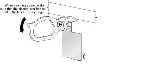
When you install a SIP, always use the ejector levers to ensure that the SIP is correctly aligned with the backplane connector; the connector pins should make contact with the backplane in the correct order, indicating that the SIP is fully seated in the backplane. A SIP that is only partially seated in the backplane will cause the router to hang and subsequently crash.
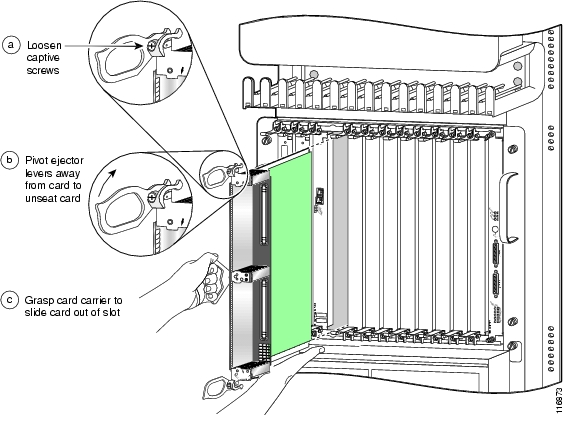
Removing a SIP

If you are replacing a failed SIP, remove the existing SIP first, then install the new SIP in the same slot. To remove a SIP, use Figure 4-2 as a reference and follow these steps:


Step 1 Attach an ESD-preventive wrist strap and follow its instructions for use.

Step 2 Disconnect and remove all interface cables from the ports; note the current connections of the cables to the ports on the SIP.

Step 3 Detach the SIP cable-management bracket from the SIP.

Step 4 Use a screwdriver to loosen the captive installation screw at each end of the SIP faceplate. (See Figure 4-2a.)

Figure 4-2 SIP Removal and Installation


Caution When you remove a SIP, always use the ejector levers to ensure that the SIP connector pins disconnect from the backplane in the logical sequence expected by the router. Any SIP that is only partially connected to the backplane can halt the router.

Step 5 Simultaneously pivot the ejector levers away from each other to release the SIP from the backplane connector. (See Figure 4-2b.)

Step 6 Grasp the ejector levers and pull the SIP halfway out of the slot.

Step 7 Grasp the SIP by the handle and gently pull it straight out of the slot, keeping your other hand under the SIP to guide it. (See Figure 4-2c.) Avoid touching the SIP printed circuit board, components, or any connector pins.

Step 8 Place the removed SIP on an antistatic mat, or immediately place it in an antistatic bag if you plan to return it to the factory.

Step 9 If the SIP slot is to remain empty, install a blank filler plate (Product Number MAS-GSR-BLANK) to keep dust out of the chassis and to maintain proper airflow through the SIP compartment. Secure the SIP blank filler plate to the chassis by tightening its captive installation screws.


Installing a SIP

A SIP slides into almost any available SIP slot and connects directly to the backplane. If you install a new SIP, you must first remove the SIP blank filler plate from the available slot.


Note Refer to the installation and configuration guide for your router for information on SIP slot types, slot width, and slot location.


Caution The router may indicate a hardware failure if you do not follow proper procedures. Remove or insert only one SIP at a time. Allow at least 15 seconds for the router to complete the preceding tasks before removing or inserting another SIP.

To install a SIP, follow these steps:


Step 1 Attach an ESD-preventive wrist or ankle strap and follow its instructions for use.

Step 2 Choose an available SIP slot for the SIP, and verify that the SIP interface cable is long enough for you to connect the SIP with any external equipment.


Caution To prevent ESD damage, handle SIPs by the captive installation screws, the provided handle, ejector levers, or the card carrier edges only. Do not touch any of the electrical components or circuitry.

Step 3 Grasp the handle of the SIP with one hand and place your other hand under the card carrier to support the weight of the card; position the card for insertion into the card cage slot. Avoid touching the SIP printed circuit board, components, or any connector pins.

Step 4 Carefully slide the SIP into the slot until the ejector levers make contact with the edges of the card cage, then stop when the ejector lever hooks catch the lip of the card cage. If they do not catch, try reinserting the SIP until the ejector lever hooks are fully latched. (See Figure 4-3.)

Figure 4-3 Ejector Levers


Caution When you install a SIP, always use the ejector levers to ensure that the card is correctly aligned with the backplane connector, the card connector pins make contact with the backplane in the correct order, and the card is fully seated in the backplane. A card that is only partially seated in the backplane can cause the router to hang and subsequently crash.

Step 5 Simultaneously pivot both ejector levers toward each other until they are perpendicular to the SIP faceplate. This action firmly seats the card in the backplane.

Step 6 Use a 3/16-inch flat-blade screwdriver to tighten the captive installation screw on each end of the SIP faceplate to ensure proper EMI shielding and to prevent the SIP from becoming partially dislodged from the backplane.


Caution To ensure adequate space for additional SIPs, always tighten the captive installation screws on each newly installed SIP before you insert any additional SIPs. These screws also prevent accidental removal and provide proper grounding and EMI shielding for the router.

Step 7 Install the SPAs. Refer to "Installing and Removing a Shared Port Adapter".

Step 8 Install the SFP modules in the SPAs that use them. Refer to "Installing and Removing a Shared Port Adapter".

Step 9 Install the interface cables.


hometocprevnextglossaryfeedbacksearchhelp

Posted: Wed Jul 18 19:18:07 PDT 2007
All contents are Copyright © 1992--2007 Cisco Systems, Inc. All rights reserved.
Important Notices and Privacy Statement.