|
|

Table Of Contents
Configuring the VPN Acceleration Module
Using the EXEC Command Interpreter
Configuring IKE Policies Example
Configuring IPSec Configuration Example
Basic IPSec Configuration Illustration
Monitoring and Maintaining the VAM
Configuring the VPN Acceleration Module
This chapter contains the information and procedures needed to configure the VPN Acceleration Module (VAM) in the Cisco 7100 series routers, Cisco 7200 series routers, and Cisco 7401ASR routers. This chapter contains the following sections:
•
Overview
•
•
Overview
The VAM provides encryption services for any interface in Cisco 7100 series, Cisco 7200 series routers, and Cisco 7401ASR routers. If you have previously configured IPSec on the router and you install the VAM, the VAM automatically performs encryption services.
Note
This section only contains basic configuration information for enabling encryption and IPSec tunneling services. Refer to the "IP Security and Encryption" part of the Security Configuration Guide and the appropriate IOS Release version of the Security Command Reference guide for detailed configuration information on IPSec, IKE, and CA.
Configuration Tasks
On power up if the enabled LED is on, the VAM is fully functional and does not require any configuration commands. However, for the VAM to provide encryption services, you must complete the steps in the following sections:
•
•
•
Note
Optionally, you can configure Certification Authority (CA) interoperability (refer to the "Configuring Certification Authority Interoperability" chapter in the Security Configuration Guide).
Using the EXEC Command Interpreter
You modify the configuration of your router through the software command interpreter called the EXEC (also called enable mode). You must enter the privileged level of the EXEC command interpreter with the enable command before you can use the configure command to configure a new interface or change the existing configuration of an interface. The system prompts you for a password if one has been set.
The system prompt for the privileged level ends with a pound sign (#) instead of an angle bracket (>). At the console terminal, use the following procedure to enter the privileged level:
Step 1
Router> enablePassword:Step 2
When you enter the correct password, the system displays the privileged-level system prompt (#):Router#This completes the procedure for entering the privileged level of the EXEC command interpreter.
Configuring IKE
To configure IKE, you would perform the following tasks:
If you do not specify a value for a parameter, the default value is assigned. For information on default values, refer to the "IP Security and Encryption" chapter of the Security Command Reference publication.
To configure a policy, use the following commands, starting in global configuration mode:
For detailed information on creating IKE policies, refer to the "Configuring Internet Key Exchange Security Protocol" chapter in the Security Configuration Guide publication.
Specifying an RSA Authentication Method
When you configure IKE policies, you specify one of the following RSA authentication methods:
•
Peers use certificates to exchange public keys securely; each peer has the remote peer's public signature key. When both peers have valid certificates, they automatically exchange public keys as part of any IKE negotiation in which RSA signatures are used.
Or, you can exchange public keys manually (see "Manually Configuring RSA Keys" section).
•
–
–
You specify two policies: a higher-priority policy with RSA encrypted nonces, and a lower-priority policy with RSA signatures. RSA signatures are used the first time because peers do not yet have each other's public keys. Future IKE negotiations use RSA encrypted nonces because public keys have been exchanged.
Note
Note
•
If RSA encryption is configured and signature mode is negotiated (and certificates are used for signature mode), the peer requests both signature and encryption keys. The router requests as many keys as the configuration will support. If RSA encryption is not configured, it will just request a signature key.
Manually Configuring RSA Keys
When you specify the RSA encrypted nonces authentication method, and you are not using a certification authority, you manually configure the RSA keys by performing the following tasks at each IPSec peer that uses RSA encrypted nonces in an IKE policy:
•
Generating RSA Keys
To generate RSA keys, use the following commands starting in global configuration mode:
Step 1
Router (config)# crypto key generate rsa
[usage-keys]
Generates RSA keys.
Step 2
Router# show crypto key mypubkey rsaDisplays the generated RSA public key (in EXEC mode).
Repeat the above tasks at each peer (without CA support) that uses RSA encrypted nonces in an IKE policy.
Setting ISAKMP Identity
This topic describes how to set the ISAKMP identity for each peer that uses pre-shared keys in an IKE policy.
When two peers use IKE to establish IPSec security associations, each peer sends its identity to the remote peer. Each peer sends either its host name or its IP address, depending on how you have the router's ISAKMP identity set.
By default, a peer's ISAKMP identity is the peer's IP address. If appropriate, you could change the identity to be the peer's host name instead. As a general rule, set all peers' identities the same way—either all peers should use their IP address, or all peers should use their host name. If some peers use their host name and some peers use their IP address to identify themselves to each other, IKE negotiations could fail if a remote peer's identity is not recognized and a DNS lookup is unable to resolve the identity.
To set a peer's ISAKMP identity, use the following commands in global configuration mode:
Step 1
Router (config)# crypto isakmp identity
{address | hostname}
At the local peer: Specifies the peer's ISAKMP identity by IP address or by host name.1
Step 2
Router (config)# ip host hostname
address1 [address2...address8]
At all remote peers: If the local peer's ISAKMP identity was specified using a host name, maps the peer's host name to its IP address(es) at all the remote peers. (This step might be unnecessary if the host name/address is already mapped in a DNS server.)
1 See the crypto isakmp identity command description for guidelines for when to use the IP address vs. the host name.
Repeat these tasks for each peer that uses pre-shared keys in an IKE policy.
Specifying Other Peers RSA Public Keys
At each peer, specify the other peers RSA public keys by using the following commands starting in global configuration mode:
Repeat the above tasks at each peer that uses RSA encrypted nonces in an IKE policy.
To view RSA public keys while or after you configure them, use the following command in EXEC mode:
Configuring Preshared Keys
To configure preshared keys, perform these tasks at each peer that uses preshared keys in an IKE policy:
•
•
To specify preshared keys at a peer, use the following commands in global configuration mode:
Remember to repeat these tasks at each peer that uses preshared keys in an IKE policy.
Configuring IPSec
After you have completed IKE configuration, configure IPSec at each participating IPSec peer. This section contains basic steps to configure IPSec and includes the tasks discussed in the following sections:
•
•
•
For detailed information on configuring IPSec, refer to the "Configuring IPSec Network Security" chapter in the Security Configuration Guide publication.
Creating Crypto Access Lists
Crypto access lists define which IP traffic will be protected by encryption.
Note
To create crypto access lists, use the following commands in global configuration mode:
Step 1
access-list access-list-number {deny | permit} protocol source source-wildcard destination destination-wildcard [log]
or
ip access-list extended nameSpecifies conditions to determine which IP packets are protected.1 (Enable or disable encryption for traffic that matches these conditions.)
We recommend that you configure "mirror image" crypto access lists for use by IPSec and that you avoid using the any keyword.
Step 2
Add permit and deny statements as appropriate.
Adds permit or deny statements to access lists.
Step 3
end
Exits the configuration command mode.
1 You specify conditions using an IP access list designated by either a number or a name. The access-list command designates a numbered extended access list; the ip access-list extended command designates a named access list.
For detailed information on configuring access lists, refer to the "Configuring IPSec Network Security" chapter in the Security Configuration Guide publication.
Defining Transform Sets
A transform set is a combination of security protocols and algorithms. During the IPSec security association negotiation, peers agree to use a specific transform set to protect a particular data flow.
To define a transform set, use the following commands, starting in global configuration mode:
Step 1
crypto ipsec transform-set transform-set-name transform1 [transform2 [transform3]]
Defines a transform set and enter crypto transform configuration mode.
Note
Step 2
mode [tunnel | transport]
Changes the mode associated with the transform set. The mode setting is applicable only to traffic whose source and destination addresses are the IPSec peer addresses; it is ignored for all other traffic. (All other traffic is in tunnel mode only.)
Step 3
end
Exits the crypto transform configuration mode to enabled mode.
Step 4
clear crypto sa
or
clear crypto sa peer {ip-address | peer-name}
or
clear crypto sa map map-name
or
clear crypto sa spi destination-address protocol spiClears existing IPSec security associations so that any changes to a transform set take effect on subsequently established security associations (SAs). (Manually established SAs are reestablished immediately.)
Using the clear crypto sa command without parameters clears out the full SA database, which clears out active security sessions. You may also specify the peer, map, or entry keywords to clear out only a subset of the SA database.
: Table 4-1 shows allowed transform combinations.
Table 4-1 Allowed Transform Combinations
ah-md5-hmac
AH with MD5 (HMAC variant) authentication algorithm
esp-3des
ESP with 168-bit Triple DES encryption algorithm
esp-md5-hmac
ESP with MD5 (HMAC variant) authentication algorithm
ah-sha-hmac
AH with SHA (HMAC variant) authentication algorithm
esp-des
ESP with 56-bit DES encryption algorithm
esp-sha-hmac
ESP with SHA (HMAC variant) authentication algorithm
esp-null
ESP transform without cipher
1 Pick one transform option.
2 Pick one transform option, but only if you selected esp-null or ESP encrypting transform.
To create crypto map entries that use IKE to establish the security associations, use the following commands, starting in global configuration mode:
Verifying the Configuration
Some configuration changes take effect only after subsequent security associations are negotiated. For the new settings to take effect immediately, clear the existing security associations.
To clear (and reinitialize) IP Sec security associations, use one of the commands in Table 4-2 in global configuration mode:
The following steps provide information on verifying your configurations:
Step 1
Router# show crypto ipsec transform-setTransform set combined-des-md5: {esp-des esp-md5-hmac}will negotiate = {Tunnel,},Transform set t1: {esp-des esp-md5-hmac}will negotiate = {Tunnel,},Transform set t100: {ah-sha-hmac}will negotiate = {Transport,},Transform set t2: {ah-sha-hmac}will negotiate = {Tunnel,},{esp-des}will negotiate = {Tunnel,},Step 2
Router# show crypto mapCrypto Map: "router-alice" idb: Ethernet0 local address: 172.21.114.123Crypto Map "router-alice" 10 ipsec-isakmpPeer = 172.21.114.67Extended IP access list 141access-list 141 permit ipsource: addr = 172.21.114.123/0.0.0.0dest: addr = 172.21.114.67/0.0.0.0Current peer: 172.21.114.67Security-association lifetime: 4608000 kilobytes/120 secondsPFS (Y/N): NTransform sets={t1,}Step 3
Router# show crypto ipsec sainterface: Ethernet0Crypto map tag: router-alice, local addr. 172.21.114.123local ident (addr/mask/prot/port): (172.21.114.123/255.255.255.255/0/0)remote ident (addr/mask/prot/port): (172.21.114.67/255.255.255.255/0/0)current_peer: 172.21.114.67PERMIT, flags={origin_is_acl,}#pkts encaps: 10, #pkts encrypt: 10, #pkts digest 10#pkts decaps: 10, #pkts decrypt: 10, #pkts verify 10#send errors 10, #recv errors 0local crypto endpt.: 172.21.114.123, remote crypto endpt.: 172.21.114.67path mtu 1500, media mtu 1500current outbound spi: 20890A6Finbound esp sas:spi: 0x257A1039(628756537)transform: esp-des esp-md5-hmac,in use settings ={Tunnel,}slot: 0, conn id: 26, crypto map: router-alicesa timing: remaining key lifetime (k/sec): (4607999/90)IV size: 8 bytesreplay detection support: Yinbound ah sas:outbound esp sas:spi: 0x20890A6F(545852015)transform: esp-des esp-md5-hmac,in use settings ={Tunnel,}slot: 0, conn id: 27, crypto map: router-alicesa timing: remaining key lifetime (k/sec): (4607999/90)IV size: 8 bytesreplay detection support: Youtbound ah sas:interface: Tunnel0Crypto map tag: router-alice, local addr. 172.21.114.123local ident (addr/mask/prot/port): (172.21.114.123/255.255.255.255/0/0)remote ident (addr/mask/prot/port): (172.21.114.67/255.255.255.255/0/0)current_peer: 172.21.114.67PERMIT, flags={origin_is_acl,}#pkts encaps: 10, #pkts encrypt: 10, #pkts digest 10#pkts decaps: 10, #pkts decrypt: 10, #pkts verify 10#send errors 10, #recv errors 0local crypto endpt.: 172.21.114.123, remote crypto endpt.: 172.21.114.67path mtu 1500, media mtu 1500current outbound spi: 20890A6Finbound esp sas:spi: 0x257A1039(628756537)transform: esp-des esp-md5-hmac,in use settings ={Tunnel,}slot: 0, conn id: 26, crypto map: router-alicesa timing: remaining key lifetime (k/sec): (4607999/90)IV size: 8 bytesreplay detection support: Yinbound ah sas:outbound esp sas:spi: 0x20890A6F(545852015)transform: esp-des esp-md5-hmac,in use settings ={Tunnel,}slot: 0, conn id: 27, crypto map: router-alicesa timing: remaining key lifetime (k/sec): (4607999/90)IV size: 8 bytesreplay detection support: Youtbound ah sas:For a detailed description of the information displayed by the show commands, refer to the "IP Security and Encryption" chapter of the Security Command Reference publication.
Configuration Examples
This section provides the following configuration examples:
•
•
Configuring IKE Policies Example
In the following example, three IKE policies are created, with policy 15 as the highest priority, policy 20 as the next priority, and the existing default priority as the lowest priority. It also creates a preshared key to be used with policy 20 with the remote peer whose IP address is 192.168.224.33, and a RSA encryption key with policy 30.
crypto isakmp policy 15encryption 3deshash md5authentication rsa-siggroup 2lifetime 5000crypto isakmp policy 20authentication pre-sharelifetime 10000crypto isakmp key 1234567890 address 192.168.224.33crypto isakmp policy 30encr 3desauthentication rsa-encrcrypto key pubkey-chain rsaaddressed-key 11.0.0.2address 11.0.0.2key-string305C300D 06092A86 4886F70D 01010105 00034B00 30480241 009E227B F7F489E2E980D39F 4A981644 C8A103F4 3CB1EFB1 CE8EDCC5 8E7BFDFC 6C4BCB3D 62BE76F35E5F7F43 F0841163 D234138C 09725BA6 B30F50C5 63615E0B 45020301 0001quitConfiguring IPSec Configuration Example
The following example shows a minimal IPSec configuration where the security associations will be established via IKE:
An IPSec access list defines which traffic to protect:
access-list 101 permit ip 10.0.0.0 0.0.0.255 10.2.2.0 0.0.0.255A transform set defines how the traffic will be protected. In this example, transform set "myset1" uses DES encryption and SHA for data packet authentication:
crypto ipsec transform-set myset1 esp-des esp-shaAnother transform set example is "myset2," which uses Triple DES encryptions and MD5 (HMAC variant) for data packet authentication:
crypto ipsec transform-set myset2 esp-3des esp-md5-hmacA crypto map joins together the IPSec access list and transform set and specifies where the protected traffic is sent (the remote IPSec peer):
crypto map toRemoteSite 10 ipsec-isakmpmatch address 101set transform-set myset2set peer 10.2.2.5The crypto map is applied to an interface:
interface Serial0ip address 10.0.0.2crypto map toRemoteSite
Note
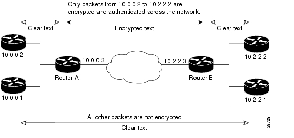
Basic IPSec Configuration Illustration
The following is an example of an IPSec configuration in which the security associations are established through IKE. In this example an access list is used to restrict the packets that are encrypted and decrypted. In this example, all packets going from IP address 10.0.0.2 to IP address 10.2.2.2 are encrypted and decrypted and all packets going from IP address 10.2.2.2 to IP address 10.0.0.2 are encrypted and decrypted. Also, one IKE policy is created.
Figure 4-1 Basic IPSec Configuration
Router A Configuration
Specify the parameters to be used during an IKE negotiation:
crypto isakmp policy 15encryption deshash md5authentication pre-sharegroup 2lifetime 5000crypto isakmp key 1234567890 address 10.2.2.3crypto isakmp identity address
Note
A transform set defines how the traffic will be protected:
crypto ipsec transform-set auth1 ah-md5-hmac esp-des esp-md5-hmacmode tunnelA crypto map joins the transform set and specifies where the protected traffic is sent (the remote IPSec peer):
crypto map toRemoteSite 10 ipsec-isakmpset peer 10.2.2.3set transform-set auth1The crypto map is applied to an interface:
interface Serial0ip address 10.0.0.3crypto map toRemoteSiteAn IPSec access list defines which traffic to protect:
access-list 101 permit ip host 10.0.0.2 host 10.2.2.2access-list 101 permit ip host 10.0.0.3 host 10.2.2.3Router B Configuration
Specify the parameters to be used during an IKE negotiation:
crypto isakmp policy 15encryption deshash md5authentication pre-sharegroup 2lifetime 5000crypto isakmp key 1234567890 address 10.0.0.3crypto isakmp identity addressA transform set defines how the traffic will be protected:
crypto ipsec transform-set auth1 ah-md5-hmac esp-des ah-md5-hmacmode tunnelA crypto map joins the transform set and specifies where the protected traffic is sent (the remote IPSec peer):
crypto map toRemoteSite 10 ipsec-isakmpset peer 10.0.0.3set transform-set auth1The crypto map is applied to an interface:
interface Serial0ip address 10.2.2.3crypto map toRemoteSiteAn IPSec access list defines which traffic to protect:
access-list 101 permit ip host 10.2.2.2 host 10.0.0.2access-list 101 permit ip host 10.2.2.3 host 10.0.0.3Troubleshooting Tips
To verify that Cisco IOS software has recognized VAM, enter the show diag command and check the output. For example, when the router has the VAM in slot 1, the following output appears:
Router# show diag 1Slot 1:VAM Encryption/Compression engine. Port adapterPort adapter is analyzedPort adapter insertion time 00:04:45 agoEEPROM contents at hardware discovery:Hardware Revision :1.0PCB Serial Number :15485660Part Number :73-5953-04Board Revision :RMA Test History :00RMA Number :0-0-0-0RMA History :00Deviation Number :0-0Product Number :CLEOTop Assy. Part Number :800-10496-04CLEI Code :EEPROM format version 4EEPROM contents (hex):0x00:04 FF 40 02 8A 41 01 00 C1 8B 31 35 34 38 35 360x10:36 30 00 00 00 82 49 17 41 04 42 FF FF 03 00 810x20:00 00 00 00 04 00 80 00 00 00 00 CB 94 43 4C 450x30:4F 20 20 20 20 20 20 20 20 20 20 20 20 20 20 200x40:20 C0 46 03 20 00 29 00 04 C6 8A FF FF FF FF FF0x50:FF FF FF FF FF FF FF FF FF FF FF FF FF FF FF FF0x60:FF FF FF FF FF FF FF FF FF FF FF FF FF FF FF FF0x70:FF FF FF FF FF FF FF FF FF FF FF FF FF FF FF FFTo see if the VAM is currently processing crypto packets, enter the show pas vam interface command. The following is sample output:
Router# show pas vam interfaceInterface VAM 1/1 :ds:0x632770C8 idb:0x62813728Statistics of packets and bytes that through this interface:18 packets in 18 packets out2268 bytes in 2268 bytes out0 paks/sec in 0 paks/sec out0 Kbits/sec in 0 Kbits/sec out83 commands out 83 commands acknowledgedppq_full_err :0 ppq_rx_err :0cmdq_full_err :0 cmdq_rx_err :0no_buffer :0 fallback :0dst_overflow :0 nr_overflow :0sess_expired :0 pkt_fragmented :0out_of_mem :0 access_denied :0invalid_fc :0 invalid_param :0invalid_handle :0 output_overrun :0input_underrun :0 input_overrun :0key_invalid :0 packet_invalid :0decrypt_failed :0 verify_failed :0attr_invalid :0 attr_val_invalid :0attr_missing :0 obj_not_wrap :0bad_imp_hash :0 cant_fragment :0out_of_handles :0 compr_cancelled :0rng_st_fail :0 other_errors :0633 seconds since last clear of countersWhen the VAM processes packets, the "packets in" and "packets out" counter changes. Counter "packets out" represents the number of packets directed to the VAM. Counter "packets in" represents the number of packets received from the VAM.
Note
To see if the IKE/IPSec packets are being redirected to the VAM for IKE negotiation and IPSec encryption and decryption, enter the show crypto eli command. The following is sample output when Cisco IOS software redirects packets to VAM:
Router# show crypto eliEncryption Layer: ACTIVENumber of crypto engines = 1.CryptoEngine-0 (slot-1) details.Capability-IPSec :IPPCP , 3DES, RSAIKE-Session : 0 active, 5120 max, 0 failedDH-Key : 0 active, 5120 max, 0 failedIPSec-Session : 0 active, 10230 max, 0 failedWhen the software crypto engine is active, the show crypto eli command yields no output.
During bootup or OIR, when the Cisco IOS software agrees to redirect crypto traffic to the VAM, it prints a message similar to the following:
%ISA-6-INFO:Recognised crypto engine (0) at slot-1...switching to hardware crypto engineTo disable the VAM, use the configuration mode crypto card shut command, as follows:
Router(config)# crypto card shut 1Router#3w4d:%ISA-6-SHUTDOWN:VAM shutting down3w4d:%ISA-6-INFO:Crypto Engine 0 in slot 1 going DOWN3w4d:...switching to software crypto engineMonitoring and Maintaining the VAM
Use the commands below to monitor and maintain the VAM:
![]()
![]()
![]()
![]()
![]()
![]()
![]()
![]()
Posted: Thu Mar 9 22:56:03 PST 2006
All contents are Copyright © 1992--2006 Cisco Systems, Inc. All rights reserved.
Important Notices and Privacy Statement.