|
|

This chapter provides an overview of the Copper Distributed Data Interface (CDDI) and Fiber Distributed Data Interface (FDDI) Extended Industry Standard Architecture (EISA) adapters used in EISA systems. It contains information about the hardware required to run the EISA adapters, and also important unpacking information.
High-performance workgroup EISA adapters connect workstations and servers to CDDI or FDDI networks. The adapters provide a single attachment or dual attachment connection that is fully compliant with Station Management (SMT) Specification, Revision 6.2 or 7.3.
The EISA adapters ensure high performance by maximizing data throughput and minimizing network overhead on the host processor. You can download firmware for convenient upgrades and eliminate the need to swap programmable read-only memory (PROM) chips.
The EISA adapters feature a highly integrated design. They contain several high-performance features to increase throughput and minimize overhead imposed on the host processor. To maximize throughput, the EISA adapters support 32-bit-wide EISA burst-data transfers. Bus mastering via two specially designed direct memory access (DMA) channels and an onboard SMT processor minimize host processor intervention.
The EISA adapters incorporate SMT 6.2 or 7.3 (the FDDI SMT specification). You can download the adapter firmware and easily update SMT versions.
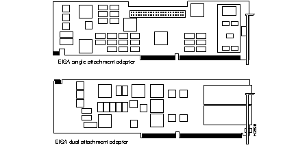
The CDDI and FDDI EISA adapters are available as either single attachment or dual attachment. The single attachment adapter consists of a single adapter card with a CDDI or FDDI port. The dual attachment adapter has two CDDI or FDDI ports. (See Figure 1-1.)

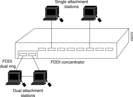
Single attachment EISA adapters can connect to another station or to a concentrator, which in turn can connect to the dual ring of an FDDI network. A single attachment configuration consists of a single attachment adapter with a CDDI or FDDI port. The single attachment adapter is a slave (S) port. The workstation FDDI interface has one physical medium dependent (PMD), one physical (PHY), one media access control (MAC), and one SMT controller.
Dual attachment EISA adapters include both A and B connectors. A workstation with the dual attachment configuration connects directly to the primary and secondary rings of an FDDI network. The workstation's FDDI interface has two PMDs, two PHYs, one MAC, and one SMT.
Figure 1-2 and Figure 1-3 show how single attachment stations and dual attachment stations are connected.


You can also connect a dual attachment station in the redundant configuration called dual homing. In Figure 1-4, a dual attachment station is connected to two concentrators that are connected to the dual ring. Port A on the station is the backup connection and only becomes active if the primary connection (port B) fails.

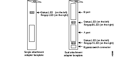
Each adapter has two LED indicators on the faceplate so that you can easily monitor the adapter's internal status and the FDDI link. Figure 1-5 shows single attachment and dual attachment FDDI EISA adapter faceplates, including the LEDs.

The status LED monitors the adapter's status. If this LED is on, the adapter has passed its internal diagnostics test.
The ringop LED monitors ring operation. If this LED is on, the adapter is connected to the FDDI ring. See the software user guide used with this adapter for a complete description of the ringop LED.
The EISA dual attachment adapter has a connector for an optical bypass switch. The two-pin mini-DIN connector is compatible with most optical bypass switches. See the section "Bypass Connector Pinouts" in the appendix "Cabling and Pinout Information" for bypass connector pinout information.
A bypass switch, when activated, removes a nonfunctioning dual attachment adapter from the ring.
This section describes the hardware and software requirements for installing the EISA adapter.
The EISA single and dual attachment adapters are designed for installation in any available EISA-compliant slot in a PC or workstation.
The requirements for the PC or workstation operating system software depend on the device drivers to be installed. Refer to the software user guide shipped with your EISA adapter driver media.
Please check your EISA adapter carefully to make sure no damage occurred during shipping.
The EISA adapter package contains the following items:
Before you open the package, inspect it for damage that might have occurred during shipping. If you notice damage, please notify your carrier. Unpack your workgroup EISA adapter to ensure that it has arrived in good working order.
Step 1 Open the package carefully. Keep the packing materials for reuse. You may need them to store, transport, or return the contents. All materials returned under warranty must be packed in their original packing materials.
Step 2 Make sure that the EISA adapter package contains the items listed in "Package Contents." If a part is missing, contact your customer service representative immediately.
Step 3 Remove the adapter from the antistatic bag and examine it for any visible damage other than that caused by shipping. If you find any damage, report it to your customer service representative immediately.
Step 4 Store the EISA adapter in the antistatic bag until you are ready to install it in your workstation.
Step 5 Always heed the handling and antistatic warning (see the chapter "Preparing for Installation") when removing the adapter from its antistatic protective package. We recommend that you wear a grounding strap whenever you are handling the workgroup EISA adapter.
Step 6 Please fill out the warranty registration information and mail or fax it to Cisco Systems.
|
|