|
|

This appendix contains pinout information for WS-C1400 Concentrator and adapter ports, the admin. interface port, and the optical bypass switch connector.
Following are the cable considerations for the CDDI ports.
Figure D-1 shows the pinout for the CDDI/MLT-3 concentrator and adapter ports for A, B, M, and S ports.

Following are pinouts and cabling requirements for CDDI UTP wiring. Table D-1 lists the pinout used for the CDDI/MLT-3 transmit and receive pairs.
| Pin | Signal | Pin | Signal |
| 1 | TX+ | 5 | - |
| 2 | TX- | 6 | - |
| 3 | - | 7 | RX+ |
| 4 | - | 8 | RX- |
The EIA-568 wiring scheme is recommended. Table D-2 lists the EIA 568 RJ-45 wiring scheme.
| Pin | Pair | Color |
|---|---|---|
| 1 | 2 | White/orange |
| 2 | 2 | Orange |
| 3 | 3 | White/green |
| 4 | 1 | Blue |
| 5 | 1 | White/blue |
| 6 | 3 | Green |
| 7 | 4 | White/brown |
| 8 | 4 | Brown |
Figure D-2 shows examples of modular cross-connect cables used for CDDI/MLT-3 connections between various devices using the CDDI-FDDI translator.

The cabling for the concentrator admin. port must be straight-through, twisted-pair. Each of the four pairs of wires that make up the twisted-pair cable must be individually twisted.
Table D-3 and Table D-4 list the pinouts for the EIA/TIA-232 admin. port.
| Switch | Terminal (DTE) | |||
|---|---|---|---|---|
| Signal | RJ-45 Pin | Direction | DB-25 Pin | Signal |
| CTS | 1 | Output | 4 | RTS |
| DSR | 2 | Output | 20 | DTR |
| RXD | 3 | Output | 2 | TXD |
| GND | 4 | - | 7 | GND |
| GND | 5 | - | - | - |
| TXD | 6 | Input | 3 | RXD |
| DTR | 7 | Input | 6 | DSR |
| RTS | 8 | Input | 5 | CTS |
Table D-4 lists the pinout for a null-modem cable used with the admin. port. Modems are considered to be data communication equipment (DCE).
| Switch | Modem (DCE) | |||
|---|---|---|---|---|
| Signal | RJ-45 Pin | Direction | DB-25 Pin | Signal |
| CTS | 1 | Output | 5 | CTS |
| DSR | 2 | Output | 6 | DCD |
| RXD | 3 | Output | 3 | RXD |
| GND | 4 | - | 7 | GND |
| GND | 5 | - | - | GND |
| TXD | 6 | Input | 2 | TXD |
| DTR | 7 | Input | 20 | DTR |
| RTS | 8 | Input | 4 | RTS |
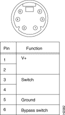
Figure D-3 shows the pinout and connector for the optical bypass switch. The connector is a standard female DIN type.

|
|