|
|

Table Of Contents
Using Cisco QAM Gateway Manager
Launching Cisco QAM Gateway Manager
Resizing the Navigation Tree and Work Area
Exiting Cisco QAM Gateway Manager
Establishing Communication with Cisco QAM Gateway Devices
Saving a Configuration to a TFTP Server
Configuring Gigabit Ethernet Input Ports into a VLAN
Setting the Output Frequency and Output Power of the QAM Channels
Setting Up, Editing, and Routing a Video Stream to QAM Channels
Configuring Program Data Delivery
Using Cisco QAM Gateway Manager
This chapter describes the steps required to launch Cisco QAM Gateway Manager and configure Cisco uMG9850 QAM modules installed in Cisco Catalyst switches.
•
Launching Cisco QAM Gateway Manager
•
•
Launching Cisco QAM Gateway Manager
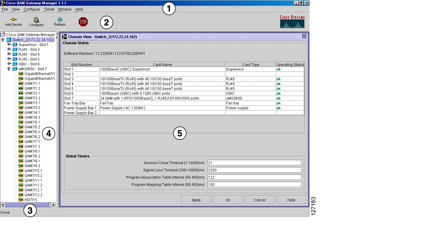
To launch Cisco QAM Gateway Manager, click on the CQGM shortcut icon on the desktop or click Start > Programs > Cisco Systems > Cisco QAM Gateway Manager. After displaying a splash screen, the Main Window appears (see Figure 3-1).
Figure 3-1 Main Window
Main Window Components
The main window (see Figure 3-1) consists of five areas:
1.
2.
3.
4.
5.
Each of these areas is discussed in the following sections.
Menu Bar
The menu bar (see Figure 3-2) provides access to common application functions and tasks (see Table 3-1).
Figure 3-2 Menu Bar
Toolbar
The toolbar ( Figure 3-3) provides quick access to some commonly performed tasks (see Table 3-2).
Figure 3-3 Toolbar
Table 3-2 Toolbar Functions
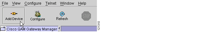
Add Device
Adds Cisco Catalyst switches to the navigation tree.
Configure
When "Cisco QAM Gateway Manager" (root) in the navigation tree (see Figure 3-1) is selected, allows configuration of SNMP polling parameters.
When device is selected in the navigation tree, configures the SNMP community string for that device.
Refresh
Refreshes current view.
Stop
Stops refresh process for current view.
Status Bar
The Status Bar (see Figure 3-4) indicates status of configuration load and refresh operations (see Table 3-3).
Figure 3-4 Status Bar
Navigation Tree
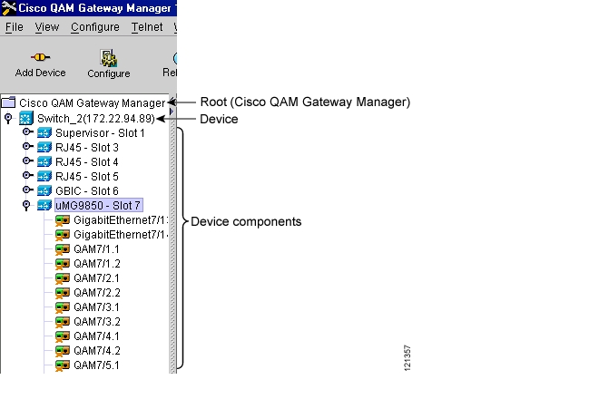
The Navigation Tree (see Figure 3-5) lists all added devices. Each entry expands to display its components. Use the scroll bar to see the full expansion.
Figure 3-5 Navigation Tree
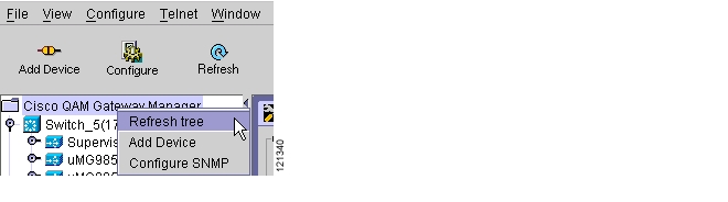
To refresh the navigation tree, select and right-click on "Cisco QAM Gateway Manager" at the top of the tree and choose Refresh tree. (See Figure 3-6.)
Figure 3-6 Refresh Navigation Tree
Note
Work Area
The Work area (see Figure 3-7) can contain a variety of view windows and configuration dialog boxes. This area changes depending on the function being performed (see Table 3-4). Up to 30 of these windows can be open simultaneously.
Figure 3-7 Work Area
Table 3-4 lists configuration, monitoring, and troubleshooting tasks that are commonly performed, and provides a cross-reference to the appropriate view or configuration window.
Tip
Table 3-4 Quick Reference—Work Area Navigation Map
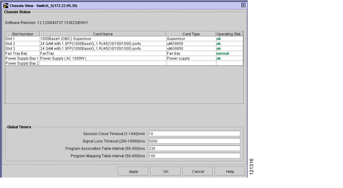
Chassis View
•
Setting Up, Editing, and Routing a Video Stream to QAM Channels.
Slot View
•
•
Configuring Gigabit Ethernet Input Ports into a VLAN (see Notes).
See also Ethernet Port View and Modifying a VLAN's Address or Administrative Status.
Setting Up, Editing, and Routing a Video Stream to QAM Channels.
Configuring Maximum Jitter for a Session.
See also QAM Channel View and Chassis View.
Session View
•
View table of all active sessions.
All Session View
•
View table of both idle and active sessions.
View individual session statistics.
Multicast Session View
•
View table for multicast sessions.
View individual session statistics.
ASI Port View
•
Setting administrative status for the port
Setting Byte Gap
Select QAM Routed
Ethernet Port View
•
Setting administrative status for the port
Setting switchport status
See also Ethernet Port View and Slot View.
QAM Channel View
•
Set administrative status for the port
Also see QAM Summary View.
Setting Up, Editing, and Routing a Video Stream to QAM Channels.
Statically Routing a Range of Program Sessions to a QAM Channel (UDP Port Mapping).
Setting the Output Frequency and Output Power of the QAM Channels.
QAM Summary View
•
Notification History
•
Telnet Window
•
Choose an already opened view from the Window menu or open a new one using the View menu. To close all views simultaneously, choose File > Close All.
Resizing the Navigation Tree and Work Area
To hide the navigation tree and expand the work area, click on the left arrow. To hide the work area and expand the navigation tree, click on the right arrow. (See Figure 3-8.)
Figure 3-8 Hide Buttons
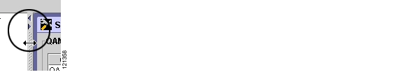
To readjust the navigation tree and work area to specific widths, place the cursor on the margin as shown in Figure 3-9. When it becomes a double-ended arrow, drag the margin to the left or right.
Figure 3-9 Sizing the Navigation Tree and Work Area
Using Help
The help files for the Cisco QAM Gateway Manager application are provided to simplify the use of the application. These files can be accessed in two ways:
•
•
Screen-Specific Help
Clicking Help in a window opens the help set and displays help files for that particular window. These files include discussions of any configuration options or read-only values present. Further navigation cross-references are included where necessary for greater understanding.
Full Help Set
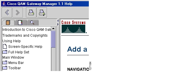
Choose Help > Contents or press F1 to open the entire help set.
The navigation pane on the left side of the window includes three tabs: the Contents tab, the Index tab, and the Search tab. Navigation and printing aids are present in the help files and in the help toolbar. See Figure 3-10.
Figure 3-10 Help Tools and Tabs
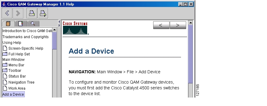
Contents Tab
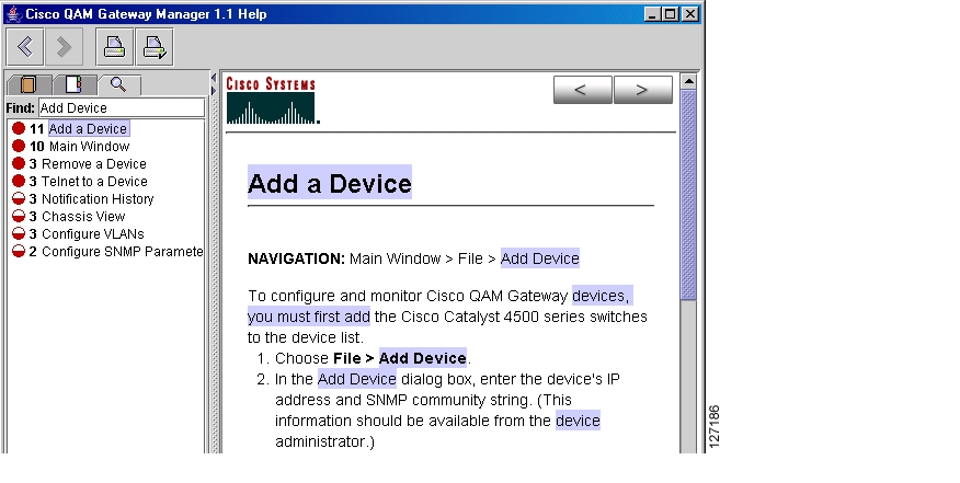
Click the Contents tab to display a Table of Contents of all help files, which allows you to click on a specific subject or task for information. See Figure 3-11.
Figure 3-11 Help File Table of Contents
Index Tab
Click the Index tab and enter an index term. The index term list is searched and if found, the page is displayed. See Figure 3-12.
Figure 3-12 Help File Index Tab
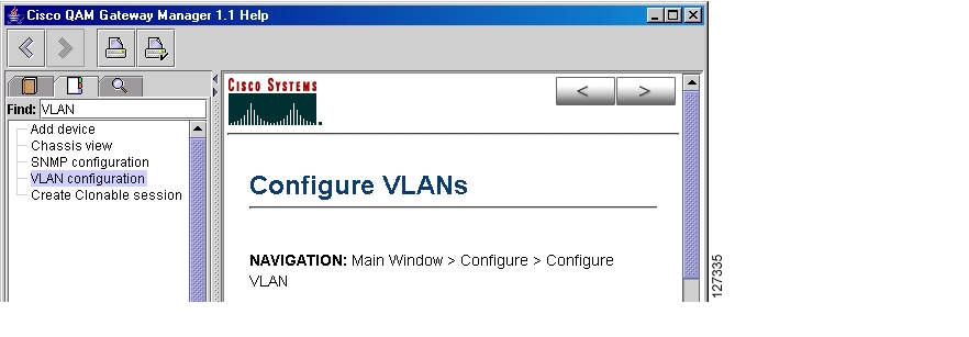
Search Tab
Click the Search tab and enter a text search term. All help files are searched for the term, and the results (number of occurrences) are displayed in the left side of the window in order of significance. The page containing the first occurrence appears on the right. See Figure 3-13.
Figure 3-13 Help Files Search Tab
Navigation
Table 3-5 shows the navigation buttons and describes their use.
Exiting Cisco QAM Gateway Manager
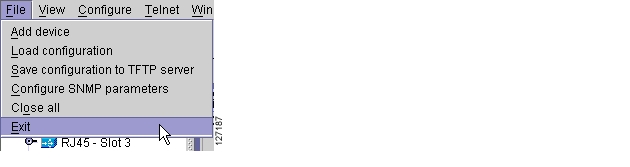
To exit the application, follow these steps:
Step 1
•
Figure 3-14 File Exit
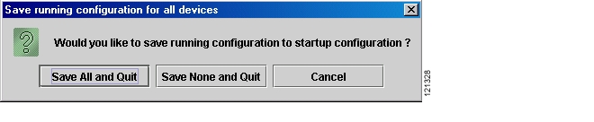
The Save Running Configuration dialog box appears (see Figure 3-15).
Figure 3-15 Save Running Configuration
Step 2
Note
Establishing Communication with Cisco QAM Gateway Devices
Adding a Device
To configure and monitor Cisco QAM Gateway devices, you must first add Cisco Catalyst switches to the device list. Up to 20 devices can be managed by Cisco QAM Gateway Manager.
To add a device:
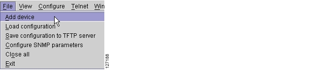
Step 1
•
Figure 3-16 Add Device Using File Menu
•
Figure 3-17 Add Device Using Add Device Button
•
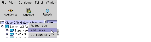
Figure 3-18 Add Device Using Right Mouse Click
Step 2
Note
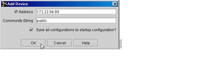
If you want to automatically save all configurations to the startup configuration, click the check box. When the check box is selected, any change made to a device using Cisco QAM Gateway Manager is automatically saved to both the running and startup configuration files of that device. If the check box is not selected, configuration changes are saved only to the running configuration.
Figure 3-19 Add Device Dialog Box
Note
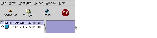
Step 3
Figure 3-20 Navigation Tree with Device Added
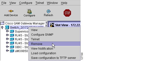
Removing a Device
To remove a Cisco Catalyst switch from the list:
Step 1
Figure 3-21 Selecting Remove
Step 2
Step 3
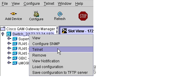
Using the Telnet Window
Use the Telnet window to enter command-line interface (CLI) commands such as show commands, or perform other configuration tasks on Cisco Catalyst switches listed in the navigation tree.
Note
Commonly used show commands are summarized in Chapter 4, "Monitoring".To access a Cisco Catalyst switch using the Telnet window:
Step 1
•
Figure 3-22 Telnet to Cisco Catalyst Switch
•
Figure 3-23 Telnet to Device Using Right-Click
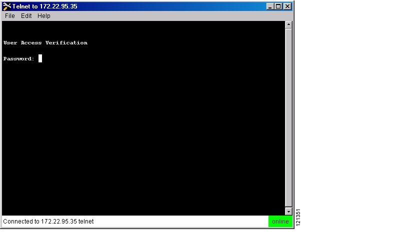
The Telnet window appears (see Figure 3-24).
Figure 3-24 Telnet Window
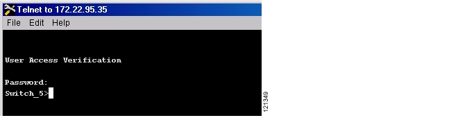
Step 2
Figure 3-25 Logged on to the Switch
Step 3
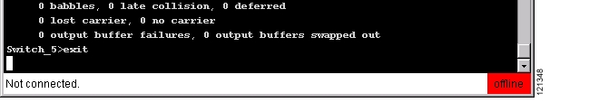
Step 4
Figure 3-26 Exiting Telnet Session
Step 5
Configuration Tasks
The following configuration tasks can be accomplished using Cisco QAM Gateway Manager. Instructions for each are provided in the subsections that follow.
•
•
•
•
•
Loading a Configuration
You can copy the Cisco Catalyst switch startup configuration to the running configuration, copy the running configuration to the startup configuration, or load a configuration file from a TFTP server to the running configuration or the startup configuration of the switch.
Copying the Startup Configuration to Running Configuration
To copy the switch startup configuration to the running configuration:
Step 1
(see Figure 3-27).Figure 3-27 Load Configuration
Step 2
Figure 3-28 Startup Configuration Button
Step 3
Step 4
Copying the Running Configuration to Startup Configuration
To copy the switch running configuration to the startup configuration:
Step 1
Figure 3-29 Load Configuration
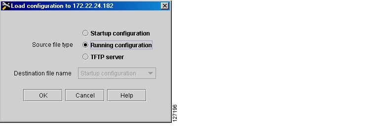
Step 2
Figure 3-30 Running Configuration Button
Step 3
Step 4
Loading a Configuration from a TFTP Server
To load a startup configuration or a running configuration from a TFTP server to the Cisco Catalyst switch:
Step 1
Figure 3-31 Load Configuration
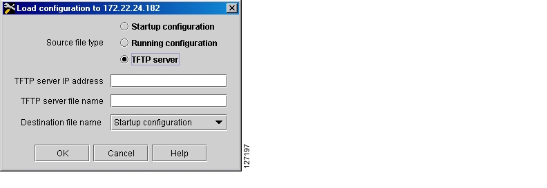
Step 2
Figure 3-32 TFTP Server Button
Step 3
Step 4
Step 5
Step 6
Note
Configuring SNMP Parameters
Cisco QAM Gateway Manager uses Simple Network Management Protocol (SNMP) and a special management information base (MIB) to manage Cisco QAM Gateway devices. Two SNMP parameters, Polling Interval and SNMP Community String, can be set using Cisco QAM Gateway Manager as described in the following sections.
Setting SNMP Polling Interval
The polling interval determines how frequently Cisco QAM Gateway Manager requests status information from each of the managed devices.
To set the SNMP polling parameters for all devices:
Step 1
•
Figure 3-33 Using File Menu
•
Figure 3-34 Using Right Click
•
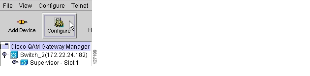
Figure 3-35 Using the Tool Bar
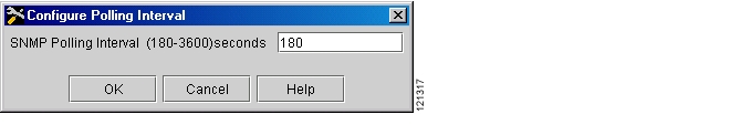
Step 2
Figure 3-36 Polling Interval Configuration Dialog Box
Step 3
Setting the SNMP Community String
If the system administrator changes the community string on the Cisco Catalyst switch, use this function to set the new SNMP community string for that switch in Cisco QAM Gateway Manager.
To set the community string:
Step 1
•
Figure 3-37 Using File Menu
•
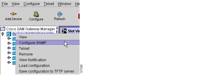
Figure 3-38 Using Right Click
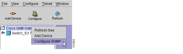
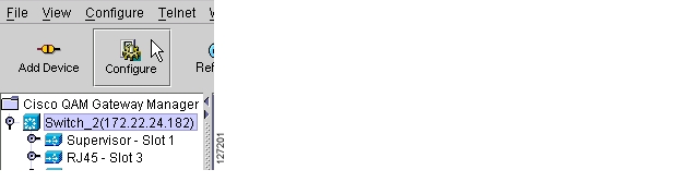
•
Figure 3-39 Using Configure Button
Step 2
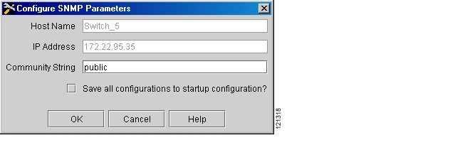
Figure 3-40 Configure SNMP Parameters Dialog Box
Step 3
Saving a Configuration to a TFTP Server
The startup configuration or the running configuration of a Cisco Catalyst switch can be saved to a TFTP server.
Saving the Startup Configuration to a TFTP Server
To save the startup configuration to a TFTP server:
Step 1
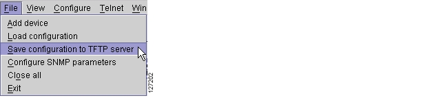
•
Figure 3-41 Save Configuration to TFTP Server
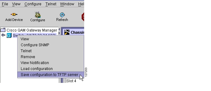
•
Figure 3-42 Save Configuration to TFTP Server Using Right-Click
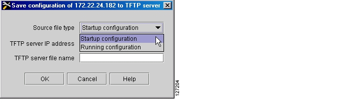
Step 2
Figure 3-43 Startup Configuration
Step 3
Step 4
Step 5
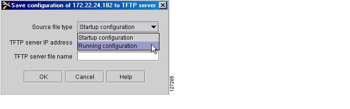
Saving the Running Configuration to a TFTP Server
To save the running configuration to a TFTP server:
Step 1
•
Figure 3-44 Save Configuration to TFTP Server
•
Figure 3-45 Save Configuration to TFTP Server Using Right-Click
Step 2
Figure 3-46 Running Configuration
Step 3
Step 4
Step 5
Configuring Gigabit Ethernet Input Ports into a VLAN
Video streams on inbound GE interfaces are included in single VLANs to use network addresses more efficiently. The IP addresses and subnet masks configured for each VLAN interface populate the IP switching table on the switch with the forwarding information needed to forward the video packets to their destination. The number and use of VLANs varies according to the programming and management needs of the system operator.
Note
Do the following to create a VLAN interface, assign an IP address to the incoming (video source) interface, and assign input Gigabit Ethernet (GE) ports to the VLAN.
Note
Modifying a VLAN's Address or Administrative Status
Step 1
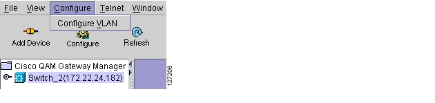
(see Figure 3-47).Figure 3-47 Configure VLAN Menu
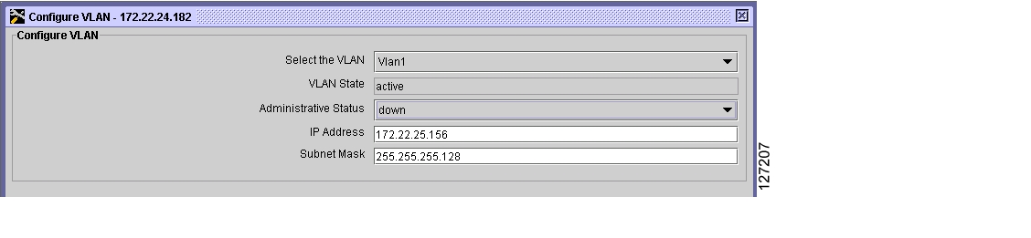
The Configure VLAN dialog box appears (see Figure 3-48).
Figure 3-48 Configure VLAN Dialog Box
Step 2
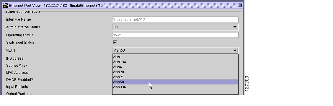
Assigning the Input GE Port to a VLAN
To assign the input gigabit Ethernet (GE) port to a VLAN:
Step 1
Step 2
Note
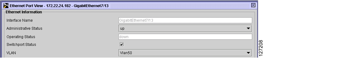
Figure 3-49 Selecting Switchport
Step 3
Figure 3-50 Selecting the VLAN
Step 4
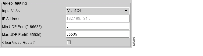
Configuring Video Routing
This configuration task sets up the routing of UDP/IP (video) packets to the Cisco uMG9850. Acting as the IP host, the supervisor engine in the switch generally receives video traffic on the IP address configured on a VLAN. When the IP address of the selected VLAN is configured as the destination IP address of the video packets, any video packet destined for this IP address—and whose destination port number matches the UDP range specified for video—is routed to the selected Cisco uMG9850. For further discussion of this process, refer to Configuring the Cisco uMG9850 QAM Module.
Step 1
Figure 3-51 Configure Video Routing
Step 2
Step 3
Note
Step 4
Step 5
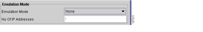
Setting Emulation Mode
You can configure the Cisco uMG9850 to emulate the UDP port mapping of third-party QAM gateways that accommodate fixed QAM-channel groups of 8 or 24 channels each. Up to three 8-channel gateways or one 24-channel gateway can be emulated. The user's mappings are converted to the scheme used by the Cisco uMG9850, and then are reconverted to the user's mapping scheme.
To set emulation mode:
Step 1
Figure 3-52 Emulation Mode Section
Step 2
Figure 3-53 Selecting Emulation Mode
Values are:
•
•
•
•
Step 3
•
•
•
Step 4
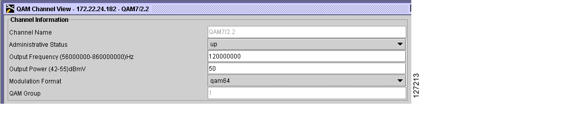
Setting the Output Frequency and Output Power of the QAM Channels
Each F-connector (QAM port) provides two QAM channels, and the frequency and output power are configured for both channels simultaneously. Setting frequency and power for one QAM channel automatically sets the appropriate values for the other channel in the same interface.
The Frequency value configures the frequency for the upconverter connected to a QAM port. Configuring the frequency for one QAM channel automatically configures the correct frequency for the other QAM channel in its upconverter group. The frequency bandwidth of each QAM upconverter block is 12 MHz. Consequently, if slot/port.1 is set to frequency f1, then slot/port.2 is automatically set to frequency f1 + 6 MHz. Similarly, if slot/port.2 is set to frequency f2, then slot/port.1 is automatically set to frequency f2 - 6 MHz.
The power value configures the power level for the upconverter connected to a QAM channel. Configuring the output power for one QAM channel automatically configures the same power level for the other QAM channel in its upconverter group. If both QAM channels are up, RF power is configured to dBmV + 3 dBmV. If only one channel is up, RF power is configured to dBmV. If no channel is up, RF power is not configured.
Setting the Output Frequency
To set the output frequency of the QAM channel:
Step 1
Figure 3-54 Setting the QAM Channel Frequency and Output Power in QAM Channel View
Step 2
Step 3
Note
Setting the Output Power
To set the QAM channel output power:
Step 1
Step 2
Step 3
Setting Up, Editing, and Routing a Video Stream to QAM Channels
Setting the Modulation Format
Each Cisco uMG9850 has six modulator groups, yielding a total of 24 channels per module. Setting the modulation format on one QAM channel applies the same format to all four QAM channels in a modulator group. For example, QAM channels 5/1.1, 5/1.2, 5/2.1, and 5/2.2.
To set the modulation format for the QAM channel:
Step 1
Step 2
Note
Step 3
Note
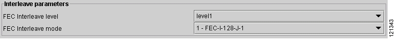
Configuring the FEC Interleave Level and Mode
The FEC interleave settings set the Reed-Solomon forward error correction (FEC) interleave level and mode on a QAM port. Forward error correction reduces bit error rate (BER) in data transmission by correcting recovered bit errors in the demodulator. Interleaving is a technique that reorders (in time) individual code-word bits with other code-word bits to spread error bursts over many different code words. The technique used is compliant with ITU J.83, Annex B.
Setting the interleave level and mode on any of the 12 QAM interfaces (ports) sets the QAM symbol rate on that port only. If the interleave level and mode is set on one QAM channel, the same value is applied to all four QAM channels in a modulator group.
Caution
To configure the FEC interleave level and mode:
Step 1
Figure 3-55 Setting the FEC Interleave Level and Mode
Step 2
Note
Step 3
Note
Step 4
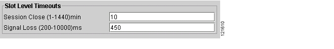
Statically Setting Session Timeouts
You can statically set a session timeout for a single Cisco uMG9850 QAM module or for the entire Cisco Catalyst switch to determine when the session is closed once packets no longer come into the session. You can also set the time following the absence of packets, at which a loss of signal is reported. Use global timeouts to address the entire switch or QAM gateway, and slot-level timeouts to address an entire module in a given slot. The options and parameters are the same in both cases.
Note
When a session is inactive, this means that the Cisco uMG9850 or has not received any video packets for the given session's User Datagram Protocol (UDP) port for the period determined by the global or slot-level timeout signal-loss. The session still exists, and is listed following a show command. If packets start arriving before the timer set by slot-level session-close timeout or global session-close timeout counts down, the session becomes active.
The value for slot-level timeout signal-loss or global timeout signal-loss should always be larger than the value configured for jitter. See Configuring Maximum Jitter for a Session.
To configure global timeouts:
Step 1
Figure 3-56 Setting Global Timers
Step 2
Step 3
Step 4
To configure slot-level timeouts:
Step 1
Figure 3-57 Setting Slot-Level Timers
Step 2
Step 3
Step 4
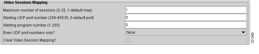
Statically Routing a Range of Program Sessions to a QAM Channel (UDP Port Mapping)
The UDP port number of each program session allows each session to be routed to a designated QAM channel by default. You can overwrite the default routing (which is signaled by the port number) and route a range of program sessions to a QAM channel.
To route a range of program sessions to a QAM channel:
Step 1
Figure 3-58 Statically Routing a Range of Program Sessions to a QAM Channel
Note
Step 2
Step 3
Step 4
Step 5
Step 6
Note
Step 7
Note
Video session mapping cannot be changed if the Cisco uMG9850 is set to emulation mode.Configuring Maximum Jitter for a Session
You can set the maximum allowable network jitter (packet latency variation) for a specified UDP port session. This global video setting affects the overall packet latency (at the buffer level) within an entire Cisco uMG9850.
Note
To configure maximum jitter:
Step 1
Figure 3-59 Setting the Jitter Specification
Step 2
Tip
The value for global timeout signal loss or slot-level timeout signal loss should always be larger than the value configured for jitter.Step 3
Setting Up PSI Parameters
You can set up various program-specific information (PSI) parameters, either globally (for the entire switch) or on an individual QAM channel.
Note
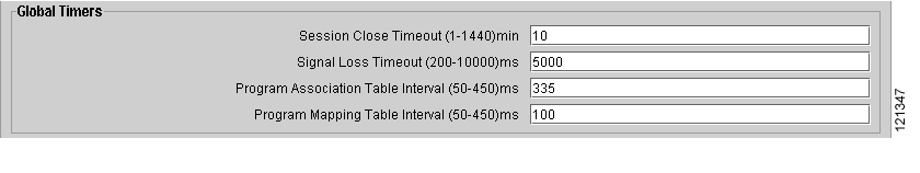
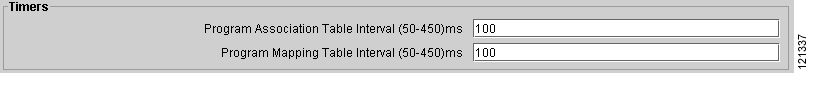
Setting PMT and PAT Intervals for the Switch
The Program Association Table (PAT) interval sets the interval at which the PAT is distributed for all Cisco uMG9850 modules in the switch. Changing the default rate in this configuration mode overwrites the rate for the switch.
The Program Mapping Table (PMT) interval sets the interval at which the PMT is distributed to all Cisco uMG9850 modules in the switch. Changing the default rate in this configuration mode overwrites the rate for the switch.
To set PMT and PAT intervals for the switch:
Step 1
Figure 3-60 Setting PSI Parameters (Switch) in Chassis View
Step 2
Step 3
Step 4
Setting PMT and PAT Intervals for a QAM Channel
These parameters set the intervals at which an individual QAM channel distributes the PAT and PMT.
To set these parameters:
Step 1
Figure 3-61 Setting PSI Parameters
Step 2
Step 3
Step 4
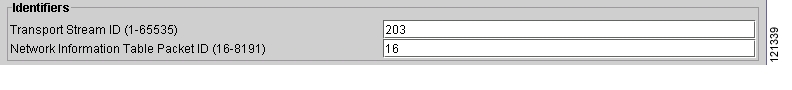
Setting TSID and NIT-PID Values
At each hub, each QAM channel must have a unique transport stream ID (TSID). The software checks for and guarantees the uniqueness of a TSID within a chassis only. These identifiers specify the TSID used to identify transport stream packets sent on the QAM channel and the packet ID (PID) used to identify Network Information Table (NIT) packets sent on a QAM port.
Caution
The PID for the network information table, or NIT-PID, can be configured from the QAM interface. If the NIT-PID is already used as a video, audio, or data PID, the configuration is rejected.
For the transport stream that is to be transmitted over a QAM channel, you must configure the TSID and NIT-PID values for that channel.
To set these parameters:
Step 1
Figure 3-62 Setting TSID and NIT-PID Values (in QAM Channel View)
Step 2
Step 3
Step 4
Configuring Program Data Delivery
The Program Data Delivery (PDD) support provided by the Cisco uMG9850 and QAM module makes possible the delivery of electronic program guide (EPG) data, other client data, and navigation data to a client application running on the set-top box (STB), enabling the subscriber to browse and select content for viewing. (PDD applies to both broadcast video and video on demand.) Program data can be delivered to the STB either in-band (on a shared QAM channel with digital video services) or out-of-band (on a DOCSIS or QPSK channel). When delivered in-band, the program data is typically delivered as private data in a low-bitrate MPEG program with multiple PIDS. Most cable systems deliver such data through one or more in-band carousels to which the client tunes at startup, as well as during program navigation, as needed.
Caution
Program-related information is streamed from a server, and can be delivered to subscribers in-band through the Cisco uMG9850. The data is encapsulated as SPTS MPEG-2 streams delivered by means of IP/UDP, as regular sessions are. However, program data, unlike a normal SPTS, can be delivered by means of multicast or unicast.
To maximize the efficiency of the IP network, a single copy of a program data stream is sent to a Cisco uMG9850 QAM channel, where the stream can be cloned to one, several, or all QAM channels. Also, the program data stream may contain program clock references (PCRs), or may be a pure data stream without timing information. To support PDD and similar functionality, the Cisco uMG9850 remaps the PID, either by using the default map or a user-specified configuration.
Caution
For additional PDD information, refer to "Configuring Program Data Delivery (PDD) Features" in Configuring the Cisco uMG9850 QAM Module.
Cloning a Unicast UDP Session to One, Several, or All QAM Channels on a Module (PDD)
You can clone (map) a unicast input UDP session to one, several, or all QAM channels on a Cisco uMG9850 with a specified output-program number. Program numbers can vary.
Caution
Note
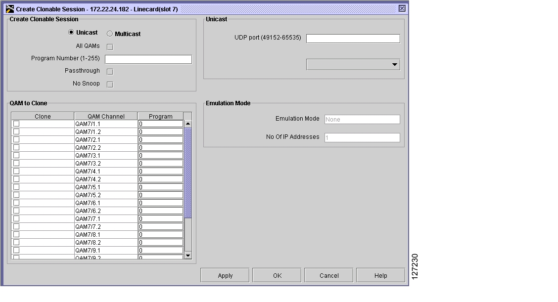
Step 1
Step 2
Figure 3-63 Create Session Dialog Box
Step 3
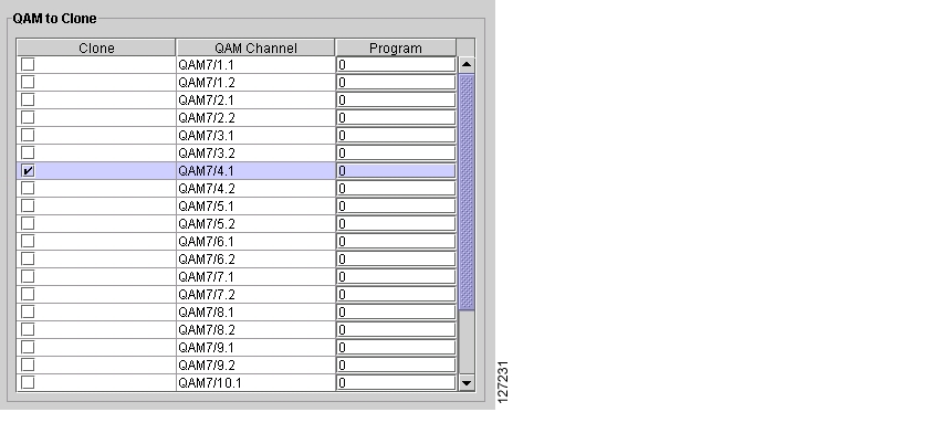
Cloning a Single Copy to a Specified QAM Channel
Caution
To clone a single copy of a PDD stream or unicast session to a specified QAM channel on a Cisco uMG9850, with a specified output-program number:
Step 1
Step 2
Figure 3-64 Selecting the QAM Channel
Step 3
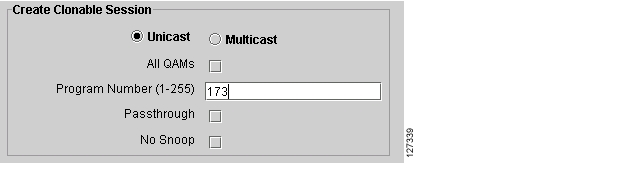
1 to 255.Figure 3-65 Output Program Number
Step 4
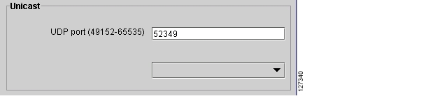
Figure 3-66 UDP Port Number
Step 5
Step 6
Cloning a Single Copy to All 24 QAM Channels
Caution
To clone a single copy of a PDD stream or unicast session to all 24 QAM channels on a Cisco uMG9850 with a specified output program number, do the following:
Step 1
Step 2
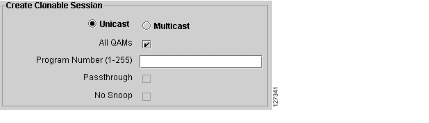
Figure 3-67 All QAMs Check Box
Step 3
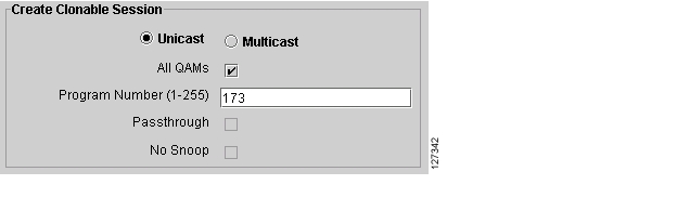
1 to 255.Figure 3-68 Output Program Number
Step 4
Figure 3-69 UDP Port Number
Step 5
Modifying or Deleting a Unicast Session
Caution
To modify a unicast session:
Step 1
Step 2
Step 3
To delete a unicast session:
Step 1
Step 2
Cloning a PDD Stream or Multicast UDP Session to one, Several, or All QAM Channels on a Module
You can clone a PDD stream or multicast session to one, several, or all QAM channels on a Cisco uMG9850. It as assumed that the multicast source is on one VLAN, and the Cisco uMG9850 is on another VLAN.
Caution
Do the following:
Step 1
Step 2
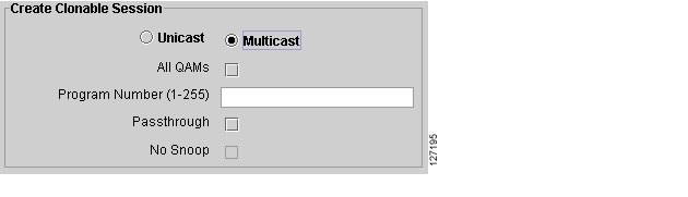
Figure 3-70 Create Clonable Session—Multicast
Step 3
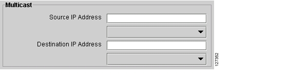
Note
Figure 3-71 Source and Destination IP Address
Step 4
Step 5
Modifying or Deleting a Multicast Session
Caution
To modify a multicast session
Step 1
Step 2
Step 3
To delete a multicast session:
Step 1
Step 2
Setting MPTS Passthrough
Digital broadcast programs are typically delivered in a multiple program transport stream (MPTS) from a statistical multiplexer (or other video source) to the Cisco uMG9850. The Cisco uMG9850 passes the MPTS through to the set-top boxes without remultiplexing the video streams. The Cisco uMG9850 may update the PCR or TSID information in the MPTS as necessary to output a valid transport stream. The Cisco uMG9850 outputs the MPTS on one or more QAM channels based on the UDP port map (for unicast sessions) or multicast group address (for multicast sessions) of the incoming stream.
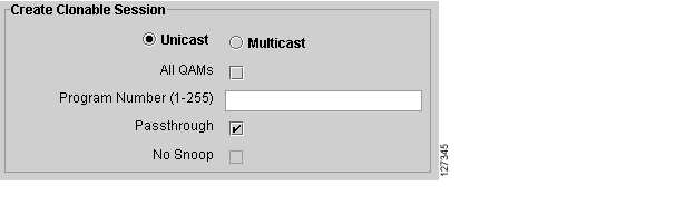
To enable MPTS passthrough on a selected Cisco uMG9850, click the Passthrough selection box (see Figure 3-72). This causes an MPTS multicast session to be passed through to the selected QAM channels. To disable MPTS passthrough, click the Passthrough selection box to remove the check mark, then click Apply.
Figure 3-72 Selecting MPTS Pass-Through
In the QAM to Clone section (see Figure 3-64), click to select the QAM channels to allow passthrough. To disallow passthrough, deselect the QAM channels, then click Apply.
Setting No-Snoop
Operators can inject externally generated service information (SI) packets onto an output QAM channel. When the Cisco uMG9850 is so configured, it does not snoop (no snoop) or modify any of the incoming packets. Rather, it simply takes each packet and inserts it into the outgoing channel along with the other VoD programs.
Note
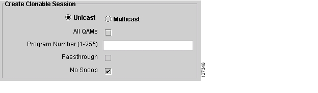
To enable or disable No Snoop, click the No Snoop selection box (see Figure 3-73).
Figure 3-73 Selecting No Snoop
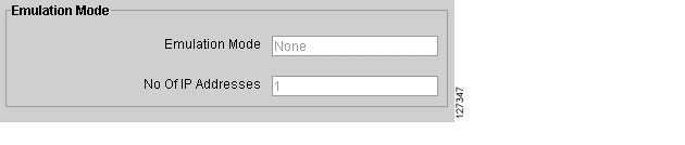
Emulation Mode
The Emulation Mode section (see Figure 3-74) is read-only and can be used for reference. To change these values, go to Slot View.
Figure 3-74 Emulation Mode (Read-Only)
![]()
![]()
![]()
![]()
![]()
![]()
![]()
![]()
Posted: Tue Apr 5 16:46:29 PDT 2005
All contents are Copyright © 1992--2005 Cisco Systems, Inc. All rights reserved.
Important Notices and Privacy Statement.