|
|

Table Of Contents
Configuring the ASI Port for QAM Channel Routing
Setting the Byte-Gap Value (S-Rate) of the ASI Port
Routing the Output of a QAM Channel to the ASI Port
Setting and Monitoring Utilization Thresholds
Warning Messages in the Notification History Table
Monitoring
This chapter provides information on the monitoring of configured Cisco uMG9850 modules, and the Cisco Catalyst switches in which they are installed, to ensure proper operation of the network. Information can be displayed using Cisco QAM Gateway Manager views and by using the command line interface within the application's Telnet window.
•
Configuring the ASI Port for QAM Channel Routing
•
Navigation Tree
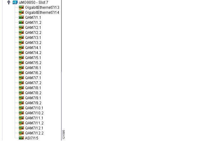
Using the navigation tree, you can observe the status of all QAM, Ethernet, and ASI ports (see Figure 4-1). When a port's administrative or operating status is down, an X appears on the icon representing that port. To see the details for a specific port, double-click on the port. The detail QAM, Ethernet, or ASI port view will appear.
Figure 4-1 Navigation Tree
Chassis View
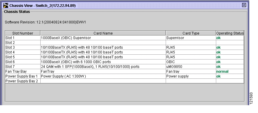
The Chassis Status section of the Chassis View displays the components of the device. For each device, each slot number is listed along with the name of the card in that slot, the card type, and the operating status. Power supplies and fan tray information also is included in the component list. (See Figure 4-2.)
Figure 4-2 Chassis Status
Slot View
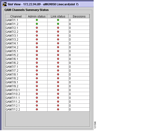
Using the Slot View QAM Channels Summary Status Table (see Figure 4-3), you can monitor the status of all the QAM channels in a specific slot. For each QAM channel, the administrative and link status (green for up and red for down), and the number of sessions on that channel are listed.
Figure 4-3 Slot View QAM Channels Summary Status
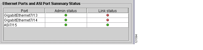
The Ethernet Ports and ASI Port Summary Status Table lists the administrative and link status for Ethernet and ASI ports on the slot—green for up and red for down. (See Figure 4-4.) Double-click on the Ethernet or ASI ports to access the Ethernet or ASI port views.
Figure 4-4 Slot View Ethernet Ports and ASI Port Summary Status
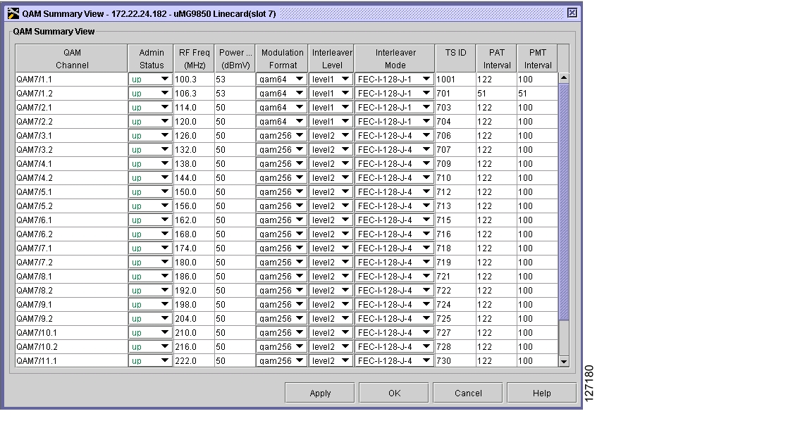
QAM Channel Summary View
The QAM Summary View (see Figure 4-5) shows on one screen the current configurations for all QAMs in a slot for the following parameters:
•
•
•
•
•
•
•
•
•
Figure 4-5 QAM Channel Summary View
Note
Tip
Telnet—CLI show commands
A variety of show commands provides additional information about the configuration and operation of the Cisco Catalyst switches managed by Cisco QAM Gateway Manager. These commands can be entered using the CLI in the Telnet window. For instructions on how to use the Telnet window, see the "Using the Telnet Window" section on page 3-16. For further information regarding the command-line interface and the commands themselves, including sample output, refer to Configuring the uMG9850 QAM Module, and Cisco Catalyst switch documentation listed in the "Related Documentation" section.
Table 4-1 describes common show commands for the Cisco Catalyst switch that can be useful for determining status of the switch related to video configuration and operation.
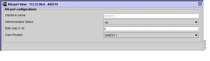
Configuring the ASI Port for QAM Channel Routing
Using the Asynchronous serial interface (ASI) port, you can set or change the gap spacing of data bytes in the ASI port output and route the input of a single QAM channel to the ASI port to monitor the channel.
Note
Setting the Byte-Gap Value (S-Rate) of the ASI Port
You can change the gap spacing of the data bytes in the output of the ASI port. The S-rate is the spacing of data bytes (the number of ASI transport null bytes between the data bytes) within the output transport stream. If there is not a sufficient number of data bytes in the stream, padding the stream with null bytes maintains the signal voltage and integrity.
To set byte gap:
Step 1
Figure 4-6 Setting the Byte-Gap Value
Step 2
Step 3
Routing the Output of a QAM Channel to the ASI Port
You can route the output of a QAM channel (a single program) to the asynchronous serial interface (ASI) port (in ASI signaling format), to monitor the output of the channel. Use a video decoder to view the selected program.
Note
To configure this parameter:
Step 1
Step 2
Step 3
Notification History Table
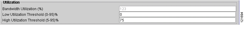
Setting and Monitoring Utilization Thresholds
It is possible that a given QAM channel can be either overwhelmed or underutilized. To monitor and correct for this, you can set both minimum and maximum bandwidth-utilization thresholds for video streams over a QAM channel. If the percentage of QAM bandwidth being used is below the value for the low utilization threshold, then the QAM channel is being underutilized. If the percentage of QAM bandwidth being used is above the value for high utilization threshold, then the QAM channel is being overutilized.
Note
To specify the high and low utilization thresholds for video streams:
Step 1
Figure 4-7 Low and High Threshold Utilization Settings
Step 2
Step 3
Step 4
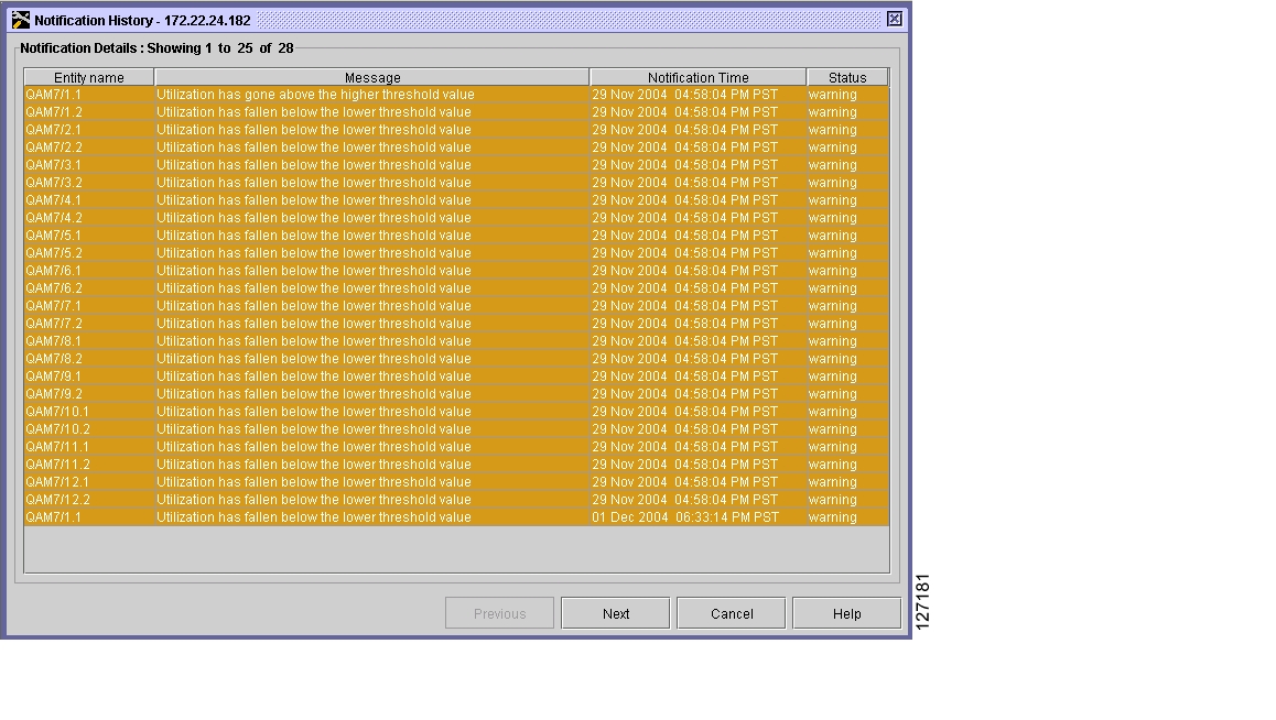
If the percentage of QAM bandwidth being used drops below the low threshold or climbs above the high threshold, or invalid PSI data is detected, an entry appears in the Notification History table (see Figure 4-8).
Figure 4-8 Notification History Table
Warning Messages in the Notification History Table
Error Message The video session nnnn has invalid PSI dataExplanation Data arriving at a VoD-enabled port does not conform to standard MPEG data. MPEG data must have PSI tables embedded within it for a receiver to correctly map the contents.
Error Message Utilization has gone above the higher threshold valueExplanation The QAM channel is being overutilized.
Error Message Utilization has fallen below the lower threshold value.Explanation The QAM channel is being underutilized.
Application Display Messages
The following is a list of typical error messages that Cisco QAM Gateway Manager may display. The exact wording of some messages may vary, and messages may appear that are not shown below.
Apply changes?
Configuration changes have been made. Do you want to copy them to the running configuration?
An unknown error occurred while configuring parameter on device at ip-address
An error has occurred while configuring the named parameter. Be sure the values entered are correct and try the operation again.
Cannot change PMT rate, programs are present.
The Program Mapping Table (PMT) can be set using the Chassis view, but cannot be changed while there are active video sessions being sent to that module. Disable the video session by disabling the GE port used by the VLAN assigned to the video route. Make the necessary changes, then re-enable the GE port.
Cisco QAM Gateway Manager is already running.
You have launched more than one instance of the application. Ensure that all but one instance has been closed.
Configuration loaded to device at ip-address
The configuration load operation has completed successfully.
Configuration loaded to device at ip-address from TFTP server ip-address.
The configuration from the specified TFTP server has successfully loaded to the device at the specified IP address.
Configuration successful.
The configuration has been copied to the running configuration of the device.
Device ip-address has changed. All open screens except chassis view will be closed for the device.
Since the information for the device has changed, all open screens may be invalid. Reopen the screens to see the updated information.
Device ip-address is not reachable or has timed out.
Cisco QAM Gateway Manager is unable to access the device at the specified address. This could be due to a reload taking place or the device is off-line. Contact your system administrator.
Device at ip-address inaccessible. Continue refreshing?
A device in the history file is not accessible, or the device is not reachable during a refresh. Do you want to keep trying to refresh this device?
Device at ip-address inaccessible. Keep in navigation tree?
Select Yes to keep the device in the Navigation Tree and mark it as offline. Select No to remove it from the Navigation Tree.
Device at ip-address has timed out. Continue refreshing?
The device has timed out during a refresh. Do you want to keep trying to refresh this device?
Enter file name.
There was an error while loading a configuration from the TFTP server. File name is required.
Enter value between lower value and upper value.
An out of range value has been entered. Enter a new value between these two.
error at ip-address. Unable to load configuration from TFTP server at ip-address
Cisco QAM Gateway Manager cannot load a configuration from the IP address specified in the Load Configuration dialog box. Verify that the address of the TFTP server is correct and that the file that you want to load is present.
Error while copying configuration from TFTP Server ip-address.
Error while copying configuration to TFTP Server.
Cisco QAM Gateway Manager cannot successfully copy a file from the TFTP server at the specified IP address. Verify that the IP address is correct and that the file to be loaded is in the TFTP server directory.
Integer value expected, Refer to the help!
A non-integer value has been entered in an integer field. Click Help and review the valid entries for the field.
Invalid session close timeout value.
An invalid value has been entered for Session Close Timeout. Enter a value from 1 to 1440 minutes.
Invalid Signal loss timeout value.
An invalid value has been entered for Signal Loss Timeout. Enter a value from 200 to 10000 milliseconds.
Invalid IP address/ host name or community string.
Device is being added and Cisco QAM Gateway Manager cannot make an SNMP query to the device.
Multicast Session Source ip-address destination ip-address is active. Shutdown VLAN before removing this session.
Self-explanatory.
No video session map available to clear!
You have already cleared the video route or no video route was configured.
Number of active sessions have changed in device at ip-address. Sessions will be rediscovered.
The number of active sessions has changed in the device at the specified address. The sessions will be re-evaluated.
Number of sessions have changed in device at ip-address. Sessions will be rediscovered.
The number of sessions has changed in the device at the specified address. The sessions will be re-evaluated.
parameter-name value is out of range for qam Channel.
An invalid parameter value has been entered. Click Help and review valid parameter ranges.
port-value UDP port is already in use in ip-address
A UDP port is already in use for one line card. Look in the CLI configuration for commands that use UDP port numbers. Look for conflicts and disable the unneeded ones.
Route IP ip-address overlays with Slot slot-number IP ip-address
The IP address might be in use by another VLAN. Make sure that the IP address is not being used by another VLAN or video route command.
Running configuration of device at ip-address saved.
The running configuration of the specified device was successfully saved to a TFTP server.
Running configuration saved to startup configuration for device at ip-address.
The running configuration of the specified device was successfully saved to the device's startup configuration.
Select a QAM gateway from the navigation tree.
View > Chassis was chosen before a device was selected in the navigation tree.
Select a device.
File > Load Configuration or File > Save Configuration to TFTP server was chosen before a device was selected in the navigation tree.
Select a Cisco Catalyst switch in navigation tree.
This function requires selection of a Cisco Catalyst Switch.
Select a uMG9850 slot.
View > Slot or View > All Sessions was chosen before a slot was selected in the navigation tree.
Select a uMG9850 module to launch the session view.
View > Sessions or View > Multicast sessions was chosen before a slot was selected in the navigation tree.
Session close timeout value out of range!
An invalid value has been entered for Session Close Timeout. Enter a value from 1 to 1440 minutes.
Signal loss timeout value out of range!
An invalid value has been entered for Signal Loss Timeout. Enter a value from 200 to 10000 milliseconds.
SNMP error occurred while configuring parameter on device at ip-address. Reason: reason
An SNMP error has occurred during configuration. Possible reasons are:
Request timed out.
SNMP response exceeds size limitation.
Variable name not found in MIB.
MIB object/instance is read-only.
Object value cannot be retrieved.
Invalid community string or access credentials.
Value/type mismatch.
Value length exceeded.
Wrong encoding for object.
Value not compatible with MIB.
Trying to create or set a nonexistent variable.
MIB variable may be in inconsistent state, not accepting set requests.
System resources unavailable for set/get operations.
Set commit has failed.
Set operation has failed, agent unable to roll back.
SNMP command cannot be authenticated, or incorrect community string found.
MIB object not responding to set operations: read-only access or incorrect community string.
Set operation failed: variable in inconsistent state.
SNMP Error: Unknown host.
The host is not recognized.
SNMP Query timed out, check the community string of the device!
The device cannot be added to the navigation tree, possibly because of an invalid community string. Check the community string and try the operation again.
SNMP polling interval configured successfully.
The polling interval for the managed devices has been successfully set.
Some fields are empty. Please fill the missing values and try again.
The configuration fields have not all been completed. Click Help to determine which fields must be completed as well as the ranges and default values for those fields.
Startup configuration of device at ip-address saved to TFTP server ip-address.
The startup configuration of the specified device was successfully saved to the specified TFTP server.
The device at address is not a uMG9800 device.
The device being added is not a Cisco Catalyst switch with a Cisco uMG9850 installed. Only those devices can be manager by Cisco QAM Gateway Manager.
There are no changes in screen to be updated.
An update has been requested but there have been no changes made.
Too many views open. Please close unneeded views.
The maximum number of simultaneously open views has been reached. In order to open additional views, some of the currently unneeded views must be closed.
Unable to load configuration from TFTP server on device ip-address from ip-address
The Load Configuration from TFTP server operation has failed. Check ip addresses for the device and the TFTP server and try the operation again.
Unable to save running configuration to startup configuration for device ip-address. Reason: SNMP Timeout or Invalid access error.
The save operation has failed. Be sure that the proper privilege levels are in effect and try the operation again.
Unable to save startup config of ip-address to ip-address (TFTP server). Reason: error string
An error has occurred while the startup configuration was being saved to the TFTP server. When possible, correct the error and try the operation again.
Unknown error occurred while refreshing device at ip-address. Continue refreshing?
An undetermined error occurred while refreshing the named device. Do you want to keep trying to refresh this device?
Unknown error occurred while refreshing device at ip-address inaccessible. Continue refreshing?
An unknown error has occurred during a refresh, and the device is currently inaccessible. Do you want to keep trying to refresh this device?
uMG9850 is in emulation mode; sessions cannot be mapped.
The uMG9850 is running in emulation mode. Video sessions mapping cannot be done in emulation mode.
Unknown Error-Device ip-address is inaccessible. Keep in the Navigation Tree?
Select Yes to keep the device in the Navigation Tree and mark it as offline. Select No to remove it from the Navigation Tree.
Value out of range. Refer to the help!
The value entered is not within the specified range. Click Help to review valid entries for this function.
Video Route VLAN vlan number overlays with Slot slot number's VLAN.
In a video route configuration, an attempt was made to assign an IP address or VLAN number already in use. The IP address and the VLAN must be unique for each video route configuration.
![]()
![]()
![]()
![]()
![]()
![]()
![]()
![]()
Posted: Tue Apr 5 16:27:18 PDT 2005
All contents are Copyright © 1992--2005 Cisco Systems, Inc. All rights reserved.
Important Notices and Privacy Statement.