|
|

Table Of Contents
Cabling the Cisco uBR 3x10 RF Switch
Installing the Header Blocks on the Cisco uBR 3x10 RF Switch
Cisco uBR10-LCP2-MC16x Cable Interface Line Card
Cisco uBR10-LCP2-MC28C Cable Interface Line Card
Cabling the Working and Protect Line Cards to the RF Switch
Cabling the DS Ports to the Input Ports on the Upconverter
Cabling the Output Ports from the Upconverter to the RF Switch
Cabling the Output RF Switch (CABLE PLANT to HUB)
Cabling the Working and Protect Line Cards to the RF Switch
Cabling the RF Switch Output (CABLE PLANT to HUB)
Cabling the Working Line Card (VXR1-VXR4)
Cabling the Protect Line Cards (VXR 5)
Cabling DS Ports to the Input Ports on the Upconverter
Cabling the Output Ports (Upconverter to RF Switch)
Cabling the RF Switch Output (CABLE PLANT to HUB)
Cabling the Working Line Card (VXR1-VXR4) to the RF Switch
Cabling the Protect Line Cards (VXR 5)
Cabling DS Ports to the Input Ports on the Upconverter
Cabling the Output Ports (Upconverter to RF Switch)
Cabling the RF Switch Output (CABLE PLANT to HUB)
Quick Start Guide
Cabling the Cisco uBR 3x10 RF Switch
Warning
Only trained and qualified personnel should be allowed to install, replace, or service this equipment. Statement 1030
1 Overview
The RF switch is designed to work with both the Cisco uBR7246VXR cable modem termination system (CMTS) and the Cisco uBR10012 CMTS in a cable headend or hub to provide N+1 redundancy for applications such as Voice over IP (VoIP). The cabling scenarios presented here are designed to help you cable the cards to the RF switch and upconverter (when used). Refer to the specific card and CMTS information to help you cable the Cisco uBR 3x10 RF Switch to cable interface line cards.
The following configurations are discussed:
•
•
•
•
•
Tip
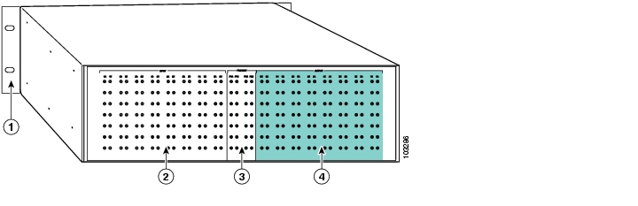
Figure 1 Rear View of the Cisco uBR-3x10 RF Switch
Mounting brackets
PROTECT MCX connector location
CMTS (working) MCX connector location
CABLE PLANT MCX connector location
Refer to the rack-mounting quick start guides for information about installing the Cisco uBR 3x10 RF Switch in a telco rack.
•
http://www.cisco.com/univercd/cc/td/doc/product/cable/rfswitch/ub10swrk.htm
•
http://www.cisco.com/univercd/cc/td/doc/product/cable/rfswitch/vxrrack.htm
For warranty information, see the Cisco uBR 3x10 RF Switch Roadmap documentation, at the following URL:
http://www.cisco.com/univercd/cc/td/doc/product/cable/rfswitch/rdmp310.htm
For information about the Vecima upconverter, go to the following URL:
http://www.vecimanetworks.com/
2 Cables and Equipment
The cables approved for use in this Cisco N+1 redundancy solution, are Mini Precision RG59 95 percent tinned copper braid with 100 percent foil shield. This cable is SDI rated with a 1 MHz to 3 GHz rating.
Cable Kit Part Numbers
•
•
•
•
Note
•
CAB-RFSW520TIMM (MC5X20S/U to RFS, dual-shielded, two 10-bundle, one 5-bundle)
or
CAB-RFSW520QTIMM (MC5X20S/U/H to RFS, quad-shielded, five 5-bundle)•
•
•
Cisco cables are color-coded for easy reference and installation. The cable color corresponds to a specific port on the card. The tables include a column for users to define ports and color definitions.
See Table 1 for a list of the cable ports and associated cable color applicable when using legacy 5-color quad-shielded cables.
See Table 2 for a list of the cable ports and associated cable color applicable when using 10-color dual/qual-shielded cables.
Table 1 MC5X20 Legacy 5-color Quad-Shielded Cable Ports and Cable Colors
User DefinedUS1 0
Red
US10
Red
DS2 0
Red
US1
White
US11
White
DS1
White
US2
Blue
US12
Blue
DS2
Blue
US3
Green
US13
Green
DS3
Green
US4
Yellow
US14
Yellow
DS4
Yellow
US5
Red
US15
Red
—
—
US6
White
US16
White
—
—
US7
Blue
US17
Blue
—
—
US8
Green
US18
Green
—
—
US9
Yellow
US19
Yellow
—
—
1 US = upstream
2 DS = downstream
Table 2 MC5X20 Ten-color Dual/Quad-Shielded Cable Ports and Cable Colors
User DefinedUS1 0
Red
US10
Grey
DS2 0
Red
US1
White
US11
Brown
DS1
White
US2
Blue
US12
Red
DS2
Blue
US3
Green
US13
White
DS3
Green
US4
Yellow
US14
Blue
DS4
Yellow
US5
Violet
US15
Green
—
—
US6
Orange
US16
Yellow
—
—
US7
Black
US17
Violet
—
—
US8
Gray
US18
Orange
—
—
US9
Brown
US19
Black
—
—
1 US = upstream
2 DS = downstream
Other Tools and Equipment
Custom cables or cable components such as header blocks, crimping tools, or connectors are available from custom cable fabricators such as WhiteSands Engineering (telephone: 1 800 586 7377), or at the following URL:
http://www.whitesandsengineering.com/
WhiteSands Part Numbers:
•
•
•
•
•
•
•
•
•
•
•
•
Upconverters and Attenuators
The Cisco uBR-MC16U cable interface line card and the Cisco uBR-MC28U cable interface line card have onboard upconverters. Upconverters are not required when these cards are used in the Cisco uBR7246VXR CMTS. However, due to a higher IF output (+42 dBmV) on other Cisco uBR-MC16 and MC28 line cards, a 10-dB attenuator may be required for UPx IF inputs.
The line cards that may require a 10-db attenuator between the DS port and the IF input on the upconverter include:
•
•
•
•
Note
3 Installing the Header Blocks on the Cisco uBR 3x10 RF Switch
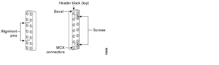
The RF cables are connected to the CMTS, PROTECT, and CABLE PLANT portions of the Cisco uBR 3x10 RF Switch using the header blocks. Header blocks are installed on the RF switch at the following locations:
•
•
•
Equipment
•
•
Tip
Step 1
Step 2
Step 3
Note
Caution
(0.5647 to 0.7909 Nm)
Figure 2 Header Block Description
4 Cabling the Cisco uBR 3x10 RF Switch with the Cisco uBR10-LCP2-MC16x or the Cisco uBR10-LCP2-MC28C Cable Interface Line Cards in a Cisco uBR10012 CMTS
A single Cisco uBR 3x10 RF Switch is cabled to cable interface line cards installed in the Cisco uBR10012 router, providing a redundancy scheme in which one protect line card (one of the eight, usually 5/1) supports from one to seven working line cards in the same chassis. The Cisco uBR10012 router supports up to eight cable interface line cards.
•
•
Note
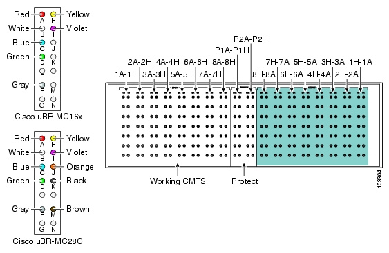
Cisco uBR10-LCP2-MC16x Cable Interface Line Card
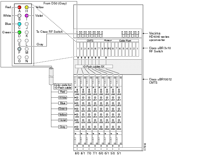
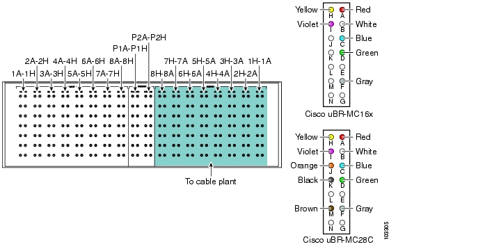
Figure 3 Table 2Cabling the Cisco uBR 3x10 RF Switch to the Cisco uBR10-LCP2-MC16x Line Cards in the Cisco uBR10012 CMTS
Table 3 Sample Mapping of a Cisco uBR10-LCP2-MC16x Cable Interface Line Card to the Cisco uBR 3x10 RF Switch
US0
A (Red)
H (Yellow)
US4
US1
B (White)
I (Violet)
US5
US2
C (Blue)
J
(Unused upstream)
US3
D (Green)
K
(Unused upstream)
(Unused upstream)
E
L
(Unused upstream)
DS0
F (Gray)
M
(Unused downstream)
(Unused downstream)
G
N
(Not connected)
1 RFS—RF switch, MCX connector on the RF switch.
Cisco uBR10-LCP2-MC28C Cable Interface Line Card
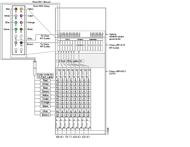
Figure 4 Cabling the Cisco uBR 3x10 RF Switch to the Cisco uBR10-LCP2-MC28C Line Card in the Cisco uBR10012 CMTS
Table 4 Sample Mapping of a Cisco uBR-MC28C Line Card to the Cisco uBR 3x10 RF Switch
US0 of first MAC domain
A (Red)
H (Yellow)
US0 of second MAC domain
US1 of first MAC domain
B (White)
I (Violet)
US1 of second MAC domain
US2 of first MAC domain
C (Blue)
J (Orange)
US2 of second MAC domain
US3 of first MAC domain
D (Green)
K (Black)
US3 of second MAC domain
(Unused upstream)
E
L
(Unused upstream)
DS0
F (Gray)
M (Brown)
DS1
(Unused downstream)
G
N
(Not connected)
1 RFS—RF switch, location of the MCX connection on the RF switch.
Cabling the Working and Protect Line Cards to the RF Switch
This section describes cabling the working and protect line cards to the RF switch.
Tip
Equipment
•
•
•
To cable the line card, complete the following steps:
Step 1
Step 2
Tip
Step 3
a.
b.
Step 4
Step 5
Step 6
Step 7
Caution
Caution
Figure 5 Cisco uBR 3x10 RF Switch—MCX Connection Locations
Cabling the DS Ports to the Input Ports on the Upconverter
Equipment
These cables are part of cable bundle kit CAB-RFSW-3X10-T.
Tip
To cable the downstream ports to the upconverter, complete the following steps.
Step 1
Step 2
Step 3
See Table 6 and Figure 6 when cabling a Cisco uBR10-LCP2-MC16x line card.
See Table 7 and Figure 7 when cabling a Cisco uBR10-LCP2-MC28C line card.
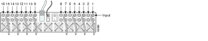
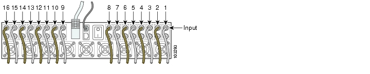
Figure 6 Cabling the Input Ports on the Upconverter (MC16x)
Figure 7 Cabling the Input Ports on the Upconverter (MC28C)
Cabling the Output Ports from the Upconverter to the RF Switch
Equipment
•
•
To cable the output ports on the upconverter to the RF switch, complete the following steps:
Step 1
Step 2
For Cisco uBR10-LCP2-MC16x cards, see Table 8.
For Cisco uBR10-LCP2-MC28C cards, see Table 9.
Step 3
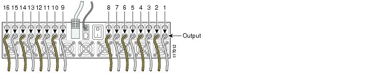
Figure 8 Cabling the Output Ports (UPx to RF Switch)
Cabling the Output RF Switch (CABLE PLANT to HUB)
The output cables are connected to the CABLE PLANT section of the RF switch. The CABLE PLANT header blocks are cabled in the opposite sequence to the CMTS and PROTECT header blocks (see Figure 9).
Equipment
•
•
Tip
To cable the output connections, complete the following steps:
Step 1
Step 2
Step 3
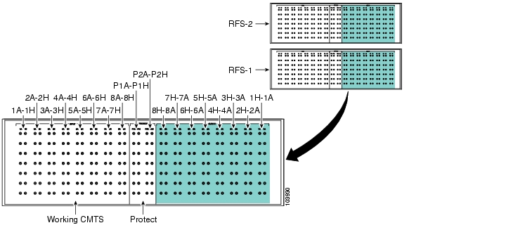
Figure 9 RF Switch Cable Plant Outputs (Turquoise)
5 Cabling the Cisco uBR 3x10 RF Switch with Cisco uBR-MC5X20S/U/H Cable Interface Line Cards in the Cisco uBR10012 CMTS
The Cisco uBR10012 router supports up to eight Cisco uBR10-MC5X20S/U/H cable interface line cards, each featuring five downstream and twenty upstream cable interfaces for a total of 40 downstream and 160 upstream interfaces in the chassis. Two Cisco uBR 3x10 RF Switchs are used in this configuration, allowing you to employ a redundancy scheme in which one protect cable interface line card (one of the eight, usually 5/1) supports from one to seven working line cards in the same chassis.
Note
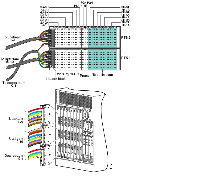
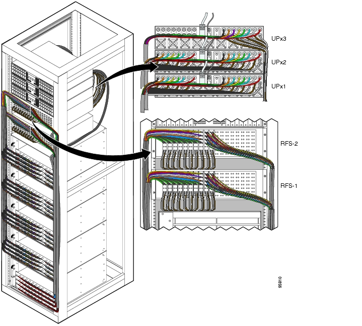
Figure 10 Cabling the Cisco uBR 3x10 RF Switch with the Cisco uBR10-MC5X20S/U/H in the Cisco uBR10012 CMTS
Cabling the Working and Protect Line Cards to the RF Switch
This section describes cabling the working and protect line cards to the RF switch. This procedure assumes that the RF cables are already installed in the universal cable holder 1 or 2 (UCH1 or UCH2) and mounted on the Cisco uBR-MC5X20S/U/H cable interface line card. If the cables have not been installed in the UCH1 or UCH2 and mounted on the line card, refer to the Cisco uBR-MC5X20S/U/H Cable Interface Line Card documentation at the following URL:
http://www.cisco.com/univercd/cc/td/doc/product/cable/ubr10k/ubr10012/frus/ubrmc520.htm
Note
Tip
Equipment
To connect the header blocks and install the cables on the RF switch, complete the following steps:
Step 1
Step 2
Step 3
For MCX cabling locations, refer to:
Table 10 for slot 8/0 and 8/1 working line card RF switch connections.
Table 11 for slot 7/0 and 7/1 working line card RF switch connections.
Table 12 for slot 6/0 and 6/1 working line card RF switch connections.
Table 13 for slot 5/0 and 5/1 working and protect line card RF switch connections.
Step 4
Caution
Step 5
Caution
Cabling the RF Switch Output (CABLE PLANT to HUB)
This section describes cabling the RF switch to the HUB or cable plant.
Note
Equipment
•
•
To cable the output connections, complete the following steps. See Figure 11.
Step 1
Note
Step 2
Step 3
Note
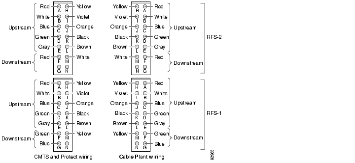
Figure 11 Cabling the Cable Plant Headers (CMTS/Protect Headers Shown for Comparison)
6 Cabling the Cisco uBR 3x10 RF Switch with Cisco uBR-MC16x Cable Interface Line Cards in the Cisco uBR7246VXR CMTS
The Cisco uBR7246VXR CMTS using five Cisco uBR7246VXR chassis, supports up to 20 Cisco uBR-MC16x (C, E, S, X or U) line cards. Each line card has one downstream and six upstream cable interfaces for a total of 20 downstream and 120 upstream interfaces for the CMTS. Two Cisco uBR 3x10 RF Switches are connected to the five Cisco uBR7246 routers, allowing you to employ a redundancy scheme in which one protect line card (in the protect router) supports from one to four working line cards in one of the four working chassis. Two upconverters are required for this configuration.
Note
Figure 12 Cisco uBR7246VXR CMTS with Cisco uBR-MC16x Cable Interface Line Cards
Cabling the Working Line Card (VXR1-VXR4)
This section describes cabling two Cisco uBR 3x10 RF switches with five Cisco uBR7246VXR routers (with Cisco uBR-MC16x line cards installed) and two Vecima upconverters. See Figure 12.
Note
Tip
Equipment
•
•
To cable the working line cards, complete the following steps. Refer to Table 14, Table 15, Table 16, and Table 17.
Step 1
Note
Step 2
Step 3
a.
b.
Step 4
Note
Figure 13 Cabling the Working Line Cards (VXR1)
Cabling the Protect Line Cards (VXR 5)
This section describes cabling the protect cards to the RF switch.
Equipment
•
•
To cable the protect line cards, complete the following steps. Refer to Table 18 and to Figure 14.
Step 1
Step 2
Step 3
Step 4
Figure 14 Cabling the Protect Line Cards (MC16x)
Cabling DS Ports to the Input Ports on the Upconverter
This section describes cabling the DS ports to the input ports on the upconverter.
Note
Equipment
•
To cable the DS ports, complete the following steps. Refer to Table 19 and Figure 15.
Step 1
Step 2
Step 3
Step 4
Step 5
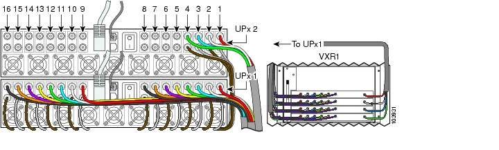
Figure 15 Cabling the Upconverter (MC16x Downstream Ports to UPx1)
Cabling the Output Ports (Upconverter to RF Switch)
This section describes cabling the output cables on the upconverter to the RF switch.
Equipment
•
To cable the output ports on the upconverter, complete the following steps. Refer to Table 20 and Figure 16.
Step 1
Step 2
Step 3
Step 4
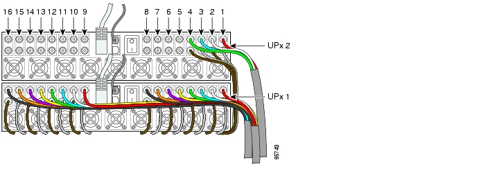
Figure 16 Output Cables (Gray and Brown)
Table 20 Upconverter Output Cables (UPx1 and UPx2) to RF Switches (RFS-1 and RFS-2)
Gray
11
RFS-2-1F
VXR1-LC1
9
RFS-2-3F
VXR3-LC1
12
RFS-2-P2F
VXR5-LC1
Brown
2
RFS-2-5F
VXR1-LC2
10
RFS-2-7F
VXR3-LC2
2
RFS-2-P1F
VXR5-LC2
Gray
3
RFS-1-1F
VXR1-LC3
11
RFS-1-3F
VXR3-LC3
3
RFS-1-P2F
VXR5-LC3
Brown
4
RFS-1-5F
VXR1-LC4
12
RFS-1-7F
VXR3-LC4
4
RFS-1-P1F
VXR5-LC4
Gray
5
RFS-2-2F
VXR2-LC1
13
RFS-2-4F
VXR4-LC1
—
—
—
Brown
6
RFS-2-6F
VXR2-LC2
14
RFS-2-8F
VXR4-LC2
—
—
—
Gray
7
RFS-1-2F
VXR2-LC3
15
RFS-1-4F
VXR4-LC3
—
—
—
Brown
8
RFS-1-6F
VXR2-LC4
16
RFS-1-8F
VXR4-LC4
—
—
—
1 Working 1 through 16 are located on UPx1
2 Protect 1 through 4 are located on UPx2
Cabling the RF Switch Output (CABLE PLANT to HUB)
This section describes cabling the output cables on the RF switch to the cable plant.
Equipment
•
•
To cable the RF switch output cables, complete the following steps. Refer to Figure 17.
Step 1
Note
Step 2
Step 3
Figure 17 RF Switch Cable Plant Outputs (Turquoise)
7 Cabling the Cisco uBR 3x10 RF Switch with Cisco uBR-MC28x Cable Interface Line Cards in the Cisco uBR7246VXR CMTS
The Cisco uBR7246VXR CMTS using five Cisco uBR7246VXR chassis, supports up to 20 Cisco uBR-MC28x (C, X, and U) line cards. Each line card has two downstream and eight upstream cable interfaces for a total of 40 downstream and 160 upstream interfaces for the CMTS. Two Cisco uBR 3x10 RF Switch are connected to the five Cisco uBR7246 routers, allowing you to employ a redundancy scheme in which one protect line card (in the protect router) supports from one to four working line cards in one of the four working chassis. Three upconverters are required for this configuration.
Note
Figure 18 Cisco uBR7246VXR CMTS with Cisco uBR-MC28x Cable Interface Line Cards
Cabling the Working Line Card (VXR1-VXR4) to the RF Switch
This section describes cabling the working line cards to the RF switch.
Note
Equipment
•
•
To cable the working line cards, complete the following steps. Refer to Table 21 for the color scheme.
Step 1
Note
Step 2
The line cards alternate between RF switch 1 and RF switch 2. Refer to the tables to see where each card is cabled. Table 21 shows the color of cable used for each connection.
Step 3
a.
b.
Step 4
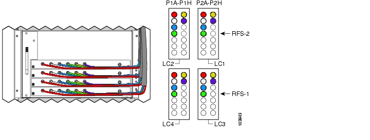
Figure 19 Cabling the Cisco uBR-MC28x Line Card in VXR1 to the RF Switches
Figure 20 Cabling the Cisco uBR 3x10 RF Switch
RF Switch 1
RF Switch 2
Cabling the Protect Line Cards (VXR 5)
This section describes cabling the protect line cards to the RF switch.
Equipment
•
•
To cable the protect line cards, complete the following steps. Refer to Table 24 and Figure 21.
Step 1
Step 2
Step 3
Step 4
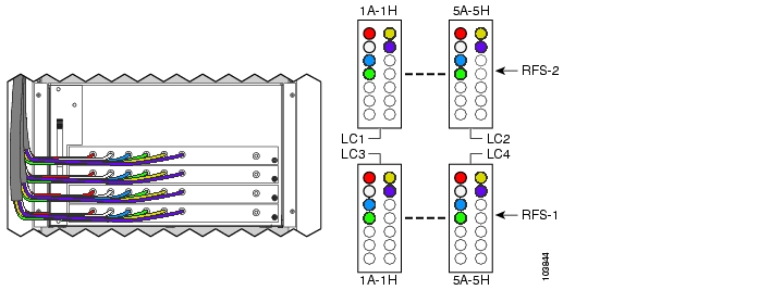
Figure 21 Cabling the Protect Line Cards (Cisco MC28x to RFS-1 and RFS-2)
Cabling DS Ports to the Input Ports on the Upconverter
This section describes cabling the DS ports to the input ports on the upconverter.
Note
Equipment
•
To cable the DS ports to the upconverter, complete the following steps. Refer to Figure 22 , and Table 25, Table 26 , and Table 27.
Step 1
Step 2
Step 3
Step 4
Step 5
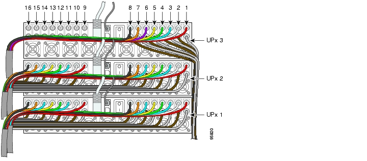
Figure 22 Cabling the Upconverter (MC28x Downstream Ports to the Upconverter)
UPx1
UPx2
UPx3
Cabling the Output Ports (Upconverter to RF Switch)
This section describes cabling the output ports on the upconverter to the RF switch.
Equipment
•
To cable the upconverter to the RF switch, complete the following steps. Refer to Table 28 and Figure 23.
Step 1
Step 2
Step 3
Step 4
Tip
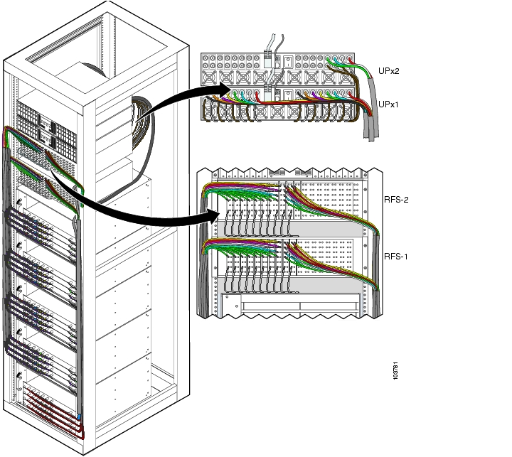
Figure 23 Cabling the Output Ports, (Gray and Brown Cables)
Cabling the RF Switch Output (CABLE PLANT to HUB)
The following section describes cabling the RF switch for output.
Note
Equipment
•
•
To cable the output to the cable plant, complete the following steps:
Step 1
Tip
A-red, B-white, C-blue, D-green. H-yellow, I-violet, J-orange, K-black.Step 2
Step 3
Figure 24 RF Switch Cable Plant Outputs (Turquoise)
8 Powering On the RF Switch
Perform this procedure only after installing and cabling the RF switch.
To power on the RF switch, complete the following steps:
Perform this procedure only after installing and cabling the RF switch.
To power on the RF switch, complete the following steps:
Step 1
Step 2
a.
b.
or
a.
b.
c.
Step 3
Step 4
9 Troubleshooting
This section covers troubleshooting the cable installation. For information about troubleshooting the Cisco uBR 3x10 RF Switch, refer to the Cisco uBR 3x10 RF Switch Installation and Cabling Guide at the following URL:
http://www.cisco.com/univercd/cc/td/doc/product/cable/rfswitch/icg/index.htm
1.
2.
(0.5647 to 0.7909 Nm).3.
4.
5.
6.
7.
![]()
![]()
![]()
![]()
![]()
![]()
![]()
![]()
Posted: Thu Oct 25 13:55:06 PDT 2007
All contents are Copyright © 1992--2007 Cisco Systems, Inc. All rights reserved.
Important Notices and Privacy Statement.