cc/td/doc/product/cable
hometocprevnextglossaryfeedbacksearchhelp
PDF

Table Of Contents

Rack-Mounting the Cisco uBR 3x10 RF Switch with the Cisco uBR7246VXR CMTS

Overview

Sample Configurations

Required Equipment

Tools and Equipment

Cables Used with These Configurations

Attaching the Brackets

Rack-Mounting the Switch

Grounding the Chassis

Technical Specifications

Related Documentation

Quick Start Guide

Rack-Mounting the Cisco uBR 3x10 RF Switch with the Cisco uBR7246VXR CMTS


Warning Only trained and qualified personnel should be allowed to install, replace, or service this equipment. Statement 1030


1 Overview

This quick start guide provides basic instructions for rack-mounting a Cisco uBR 3x10 RF Switch with the CiscouBR7246VXR CMTS.

Sample Configurations

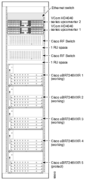
Figure 1 Cisco uBR7246VXR CMTS with the Cisco uBR-MC16x Line Cards

These illustrations show sample configurations using the Cisco uBR 3x10 RF Switch, upconverters, and the CiscouBR7246VXR CMTS.


Tip To prevent overheating, install the RFSwitch in an area that is properly ventilated or air conditioned.


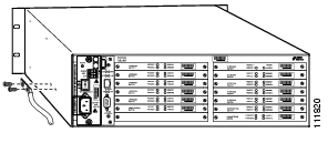
Figure 2 Cisco uBR7246VXR CMTS with the Cisco uBR-MC28C Line Cards

2 Required Equipment

The following equipment is required for rack-mounting the Cisco uBR 3x10 RF Switch in a standard 19-inch-wide 4-post equipment rack.


Note The rack-mount brackets that come in the accessory kit cannot be used with other racks, such as 23-inch telco racks


Tools and Equipment

Number 2 Phillips screwdriver

7/16-inch flat-blade screwdriver

Eight 1/32 x 3/8 slotted screws

Two M5 hex-head screws

4 AWG ground wire

Heat-shrink tubing

Ground lug

The rack-mount kit includes:

Two rack-mount brackets

Four M5 x 8-mm Phillips countersunk screws

Cables Used with These Configurations

10-m cables—CABRFSW-3X10⁻¹⁰T,
MCX to F connector

1.2-m cables—CAB-RFSW-3X10-T,
MCX to F connectors

3 Attaching the Brackets

Before proceeding with the installation, review the safety information in Cisco RF Switch Regulatory Compliance and Safety Information.


Step1 Locate the threaded holes at the rear of the chassis (both sides).

Step2 Align the first rack-mount bracket with the threaded holes in the left-rear side of the chassis.

Step3 Thread the M5 x 8 mm Phillips screws through the rack-mount bracket and into the side of the chassis.

Step4 Use the number 2 Phillips screwdriver to tighten the screws.

Step5 Repeat Step 1 through Step 4 for the other bracket.


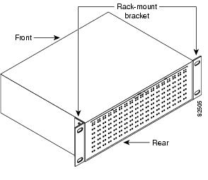
Figure 3 Rear-Mounted Brackets

4 Rack-Mounting the Switch


Caution Two people should perform this installation procedure.


Note Use all four screws to fasten the two rack-mount brackets to the rack posts, because the brackets support the weight of the chassis (36.6 lbs (16.6 kg).


Step1 Ensure that all the modules are secure in the chassis.

Step2 Position the chassis so that the rear panel is facing the same way as the connectors on the cards. See Figure1 and Figure2.


Tip To facilitate cabling, leave one RU space between the RF switch and the router, and one RU space between the two RF switches.


Step3 Slide the chassis into the rack. Use the illustrations to determine where you attach the chassis to the rack. See Figure1 and Figure2.

Step4 While keeping the brackets flush against the posts or mounting strips, position the chassis so that the holes in the brackets are aligned with those in the mounting strips.

Step5 Insert all four 1/32 x 3/8 slotted screws (two on each side) through the brackets and into the mounting strip.


Tip Insert the bottom screws first.


Step6 Tighten all the screws.


5 Grounding the Chassis


Caution Before connecting power and turning on the RF Switch, you must provide an adequate earth ground connection.


Step1 Locate the ground lug holes on the left-side rear of the chassis.

Step2 Using 4 AWG wire (recommended), insert the wire into the ground lug.

Step3 Cover any exposed wire with heat-shrink tubing.

Step4 Use the two M5 hex-head screws to attach the grounding lug to the chassis.

Step5 Attach the wire to an appropriate earth ground location.


Figure 4 Grounding Lug Location


Tip For more detailed installation instructions, refer to the Cisco uBR 3x10 RF Switch Hardware Installation and Cabling Guide.


Tip For cabling information refer to the CiscouBR 3x10 RF Switch Hardware Installation and Cabling Guide. and the cabling quick start guide for the CiscouBR7246VXR CMTS.


6 Technical Specifications

Table 1 Part Numbers and Specifications

Description
Part Num/Specification

RF Switch (3x10)

UBR-RFSW-3X10

Weight

36.6 lbs (16.6 kg)

Dimensions
(w x d x h)

19 x 15.5 x 5.25 inches
(482 x 394 x 133 mm)(

Operating
temperature

32 to 104°F (0 to +40°C)

Storage temperature

-38 to 149°F (-40 to +70°C)

Power requirement

AC

100 to 240 VAC, 50-60 Hz.

DC

-48/-60 VDC

Requires Cisco IOS Release 12.2(15)BC2


7 Related Documentation

Cisco uBR 3x10 RF Switch Hardware Installation and Cabling Guide

http://www.cisco.com/en/US/products/hw/
cable/ps2929/prod_installation_guides
_list.html

Cabling the Cisco uBR 3x10 RF Switch to a CiscouBR7246VXR Router

http://www.cisco.com/en/US/products/hw/
cable/ps2929/products_quick_start_list.html

Cisco RF Switch Regulatory Compliance and Safety Information

http://www.cisco.com/en/US/products/hw/cable/ps2929/products_regulatory_approvals_and_compliance_list.html

For information about the 1-year warranty, enter 78-10747-01C0 at the following URL:

http://www.cisco.com/univercd/cc/td/doc/
es_inpck/cetrans.htm

For VCom HD4040 series IF-to-RF upconverters information, go to the following URL:

http://www.vcom.com


hometocprevnextglossaryfeedbacksearchhelp

Posted: Fri Mar 12 08:46:50 PST 2004
All contents are Copyright © 1992--2004 Cisco Systems, Inc. All rights reserved.
Important Notices and Privacy Statement.