|
|

This chapter describes the procedures for managing Cisco uBR7200 series universal broadband routers and cable modems. Cisco Cable Manager runs as part of the Cisco Element Manager Framework (Cisco EMF) and provides the following features:
This chapter describes the following procedures:
After successfully completing the installation steps, Cisco Cable Manager can be started. To start Cisco Cable Manager server for the first time, log in as root and enter the following commands:
cd /opt/AV/bin
./av start
./av dataload
After Cisco Cable Manager has been started for the first time, it can be restarted using the command:
./av start
Cisco IP Manager and Oracle server are optional and can be installed to enable Cisco Cable Manager configuration management. If you plan to use configuration management, start the required network components and Cisco Cable Manager in the following order:
1. Oracle server
2. Cisco IP Manager
3. Cisco Cable Manager
After successfully completing the installation steps and running Oracle and Cisco IP Manager, Cisco Cable Manager can be started. To start Cisco Cable Manager server for the first time, log in as root and enter the following commands:
cd /opt/AV/bin
./av start
./av dataload
After Cisco Cable Manager has been started for the first time, it can be restarted using the command:
./av start
To access Cisco Element Management Framework (CEMF) and Cisco Cable Manager, ensure the Cisco Cable Manager server is started and complete one of the following operations:
Enter a valid username and password. The default username is admin. The default password is admin. Admin or root users can add additional users and passwords.
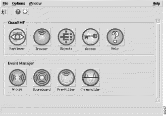
After CEMF and Cisco Cable Manager are started, the CEMF application window appears with the Launch Pad.
Figure 3-1 shows the CEMF Launch Pad.
The first step in managing a device is to deploy CEMF management containment levels and objects. To deploy containment levels and objects, click Objects. The Object tree appears with the default Manager level as the top level.
To assign additional levels and objects, from the right-click menu, select Deploy Object and choose the desired level. The CEMF management levels are region, site, network, and bay. Cisco Cable Manager containment levels include Cisco uBR7200 series universal broadband routers, RF line cards, port adapters, upstream connections, and downstream connections. Cable modem objects appear under the upstream connections.
After the containment levels are created, the objects can be deployed. By default, performance polling is disabled for the deployed or discovered objects. Performance polling can be activated per Cisco uBR7200 series universal broadband router. See "Enabling/Disabling Cable Modem Performance Polling" section.
In CEMF, "deployment" can be carried out on actual or soon-to-be installed hardware devices through these methods. Cisco recommends that you "discover" each Cisco uBR7200 series universal broadband router individually.
Use the CEMF Autodiscovery function to automatically discover existing Cisco uBR7200 series universal broadband routers already physically installed on your network by IP address range of the Cisco uBR7200 series universal broadband routers and display them and their objects in the CEMF tree views. Cisco recommends that you "discover" each Cisco uBR7200 series universal broadband router individually. Due to the size restrictions of the alarm database, Cisco recommends that you reset the alarm database after the initial discovery of every 2,000 cable modems or manually delete the alarms from the alarm database.
Step 1 In the CEMF tree view, right-click the level under which you want to deploy devices. This displays the Options menu.
Step 2 Select Autodiscovery to display the Discover Network Devices dialog. Run the Discovery process as described in your CEMF documentation. You will need to enter the IP addresses, SNMP read-only string, and physical path. This read-only string needs to match the Cisco uBR7200 string setting. If the strings do not match, Cisco Cable Manager will not discover the Cisco uBR7200 series universal broadband routers. The Cisco uBR7200 series universal broadband router community strings can be set individually using the CEMF Open Configuration menu command.
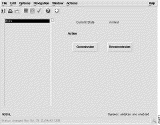
To check the status of the autodiscovery process, select a Cisco uBR7200 series universal broadband router and from the right-click menu, choose Commission/Decommission Object. The Commission/Decommission dialog appears and displays the object status. A status of "normal" indicates the Cisco uBR7200 series universal broadband router and its components have been discovered. You can also verify the status of the autodiscovery process by accessing the AV log file.
Due to the size restrictions of the alarm database, Cisco recommends that you reset the alarm database after the initial discovery of every 2,000 cable modems or manually delete the alarms from the alarm database.
To reset the alarm database after the initial discovery of every 2,000 cable modems, follow these procedures:
Step 1 Ensure you are logged in to Cisco Cable Manager server as user root.
Step 2 When all the cable modems connected to a Cisco uBR7200 series universal broadband router have been discovered, execute the /opt/AV/bin/av stop command to gracefully bring down Cisco Cable Manager.
Typically, Cisco uBR7200 series universal broadband routers are discovered individually. When all the cable modems connected to an individual Cisco uBR7200 series universal broadband router have been discovered, the numbers of lines in the /tmp/ip-address-file(s) file matches the number of lines in the /tmp/cmHashTable file.
Step 3 To stop the Object Store server, execute the /etc/init.d/S80ostore4 command.
Step 4 Move to the /opt/AV/db directory and either copy the alarm.db file to another filename and remove the original file or move the alarm.db file to another directory location.
Step 5 Ensure the OS_CACHE_SIZE is set to 64 MB. Refer to instructions under CShell, setenv OS_CACHE_SIZE 67108864.
Step 6 To restart the Object Store server, execute the /etc/init.d/S80ostore4 start command.
Step 7 To start CEMF and Cisco Cable Manager, execute the /opt/AV/bin/av start command.
Step 8 Continue the discovery process for the next Cisco uBR7200 series universal broadband router deployment and cable modem object creation. Repeat these steps to reset the alarm database after all the connected cable modems for the Cisco uBR7200 series universal broadband router have been discovered.
By default, performance polling is disabled for the deployed or discovered objects. Cable modem performance polling can be activated per Cisco uBR7200 series universal broadband router and is used to collect data for the cable modem customized report.
To enable polling for a Cisco uBR7200 series universal broadband router:
Step 1 Select the desired Cisco uBR7200 series universal broadband router in the Object or Map View.
Step 2 Select AV Tools>Open Configuration Dialog.
Step 3 Verify the COMMON-EM.mib:controllerState attribute has a value of normal. Performance polling can only be set for objects with a value of normal-.
Step 4 Change the COMMON-EM.mib:controllerAction attribute value from ERROR to startPolling.
Step 5 Click Save.
Step 6 To verify performance polling is activated, in the Open Configuration dialog box, verify the COMMON-EM.mib:controllerState value is perPolling.
As an alternative to running the automated deployment of the Autodiscovery function, the CEMF Deployment feature allows you to manually deploy containment levels and their objects or only individual objects. Cisco Cable Manager devices include Cisco uBR7200 series universal broadband routers RF line cards, port adapters, upstream connections, and downstream connections. Cable modems appear under the upstream connections.
Cisco recommends that you discover each Cisco uBR7200 series universal broadband router individually. Due to the size restrictions of the alarm database, Cisco recommends that you reset the alarm database after the initial discovery of every 2,000 cable modems or manually delete the alarms from the alarm database.
To manually discover an object:
Step 1 In the CEMF tree view, right-click Object level or the Cisco uBR7200 series universal broadband router that you wish to deploy. This displays the options menu.
Step 2 Select the desired deployment option:
For a Cisco uBR7200 series universal broadband router level, from the right-click menu:
Step 3 In the following Deployment Selection Screen, specify the desired information and click Forward:
Step 4 When deployment is complete, the Deployment Summary screen appears. Click Dismiss. Your newly deployed objects will appear in the CEMF Map View and Object Tree.
Step 5 Commission the containment level so the containment object and the manually deployed objects are synchronized.
Due to the size restrictions of the alarm database, Cisco recommends that you reset the alarm database after the initial discovery of every 2,000 cable modems or manually delete the alarms from the alarm database.
To reset the alarm database after the initial discovery of every 2,000 cable modems, follow these procedures:
Step 1 Ensure you are logged in to Cisco Cable Manager server as user root.
Step 2 When all the cable modems connected to a Cisco uBR7200 series universal broadband router have been discovered, execute the /opt/AV/bin/av stop command to gracefully bring down Cisco Cable Manager.
Typically, Cisco uBR7200 series universal broadband routers are discovered individually. When all the cable modems connected to an individual Cisco uBR7200 series universal broadband router have been discovered, the numbers of lines in the /tmp/ip-address-file(s) file matches the number of lines in the /tmp/cmHashTable file.
Step 3 To stop the Object Store server, execute the /etc/init.d/S80ostore4 command.
Step 4 Move to the /opt/AV/db directory and either copy the alarm.db file to another filename and remove the original file or move the alarm.db file to another directory location.
Step 5 Ensure the OS_CACHE_SIZE is set to 64 MB. Refer to instructions under CShell, setenv OS_CACHE_SIZE 67108864.
Step 6 To restart the Object Store server, execute the /etc/init.d/S80ostore4 start command.
Step 7 To start CEMF and Cisco Cable Manager, execute the /opt/AV/bin/av start command.
Step 8 Continue the discovery process for the next Cisco uBR7200 series universal broadband router deployment and cable modem object creation. Repeat these steps to reset the alarm database after all the connected cable modems for the Cisco uBR7200 series universal broadband router have been discovered.
After the containment levels are created, the objects can be deployed. By default, performance polling is disabled for the deployed or discovered objects. Performance polling can be activated per Cisco uBR7200 series universal broadband router. See "Enabling/Disabling Cable Modem Performance Polling" section.
After a device is discovered and deployed, Cisco Cable Manager allows you to add devices to be managed (commission) and remove devices from being managed (decommission).
You can commission/decommission single Cisco uBR7200 series universal broadband routers and all the cable modems connected to the router, a single RF line card or a single port adapter. You can also commission all the objects under a Cisco uBR7200 series universal broadband router by decommissioning the router and then recommissioning it.
To commission or decommission an object, select the desired object and from the right-click menu, select the displayed commission/decommision command. The Open Commission/Decommision dialog box appears.
Figure 3-2 shows the Commission/Decommission dialog box.
In the Cisco Cable Manager Launch Pad, select the desired view and toggle to the desired cable object. To access the Cisco Cable Manager features, select the desired object and choose an option from the right-click menu.
Cisco Cable Manager enables you to perform the following Cisco uBR7200 series router management features:
Cisco Cable Manager integrates fault management with Cisco EMF/EM so you can:
To display event messages:
By default, event messages are stored for seven days. This setting is controlled by the alarmDirServer.ini file located in the /opt/AV/config/init directory.
Make sure the desired Cisco uBR7200 series universal broadband routers are configured to send traps to the Cisco Cable Manager. This configuration involves enabling traps, specifying a source interface for SNMP traps, setting destination host IP addresses, and ensuring the cable modem MIB is set.
To enable the cable-specific SNMP traps, configure the Cisco uBR7200 series universal broadband router with the following commands:
snmp-server enable traps
snmp-server trap-source [interface port/slot]
snmp-server host [IP address] [community string]
Multiple host IP addresses can be entered to forward traps to multiple SNMP management stations.
The SetCmOnOff.pl script is an additional tool distributed with the Cisco Cable Manager and located under /opt/AV/config/scripts. This script enables the cdxCmtsCmOnOffTrap with a default interval of 600 seconds (10 minutes). The interval determines how long the system waits after the event occurs before sending out the trap message. You have the option of not using this script if other tools are available.
To enable the cable modem on/off trap notification:
Step 1 Launch an xterm and execute:
/opt/AV/bin/av shell
Step 2 Change to /opt/AV/config/scripts.
Step 3 Execute:
./SetCmOnOff.pl ip-address-uBR read-comm-str write-comm-str interval-in-seconds
where interval-in-seconds is greater than 0.
Table 3-1 shows the traps supported for Cisco uBR7200 series universal broadband router and cable modem management.
| Trap | Description |
|---|---|
Cable modem on | Cable modem connected to a Cisco uBR7200 series universal broadband router turns on or off. |
ccCopy Completion | The notification is used to indicate that a config-copy operation to or from the agent has been completed. |
ciscoConfigManEvent | Notification of a Configuration Management event as recorded in the History Event Table. |
ciscoEnvMonShutdownNotification | A ciscoEnvMonShutdownNotification is sent if the environmental monitor detects a test point reaching a critical state and is about to initiate a shutdown. This notification contains no objects so that it may be encoded and sent in the shortest amount of time possible. Even so, management applications should not rely on receiving such a notification as it may not be sent before the shutdown completes. |
ciscoEnvMonVoltageNotification | A ciscoEnvMonVoltageNotification is sent if the voltage measured at a given test point is outside the normal range for the test point (that is, at the warning, critical, or shutdown stage). Since such a notification is usually generated before the shutdown state is reached, it can convey more data and has a better chance of being sent than does the ciscoEnvMonShutdownNotification. |
ciscoEnvMonTemperatureNotification | A ciscoEnvMonTemperatureNotification is sent if the temperature measured at a given test point is outside the normal range for the test point (that is, at the warning, critical, or shutdown stage). Because such a notification is usually generated before the shutdown state is reached, it can convey more data and has a better chance of being sent than does the ciscoEnvMonShutdownNotification. |
ciscoEnvMonFanNotification | A ciscoEnvMonFanNotification is sent if any one of the fans in the fan array (where extant) fails. Because such a notification is usually generated before the shutdown state is reached, it can convey more data and has a better chance of being sent than does the ciscoEnvMonShutdownNotification. |
ciscoEnvMonRedundantSupplyNotification | A ciscoEnvMonRedundantSupplyNotification is sent if the redundant power supply (where extant) fails. Because such a notification is usually generated before the shutdown state is reached, it can convey more data and has a better chance of being sent than does the ciscoEnvMonShutdownNotification. |
ciscoFlashCopyCompletionTrap | A ciscoFlashCopyCompletionTrap is sent at the completion of a Flash copy operation if such a trap was requested when the operation was initiated. |
Link up | The link between a Cisco uBR7200 series universal broadband router and a cable modem goes up or down. |
Cold start | A Cisco uBR7200 router is cold started, warm started, or reloaded. |
SNMP authentication failed | Community string settings between a management station and an SNMP-enabled device did not match. |
Cisco Cable Manager allows you to set thresholds on a Cisco uBR7200 series universal broadband router with specified polling intervals to generate alarm notification when a threshold level is exceeded. Thresholds can be set for the following Cisco Cable Manager attribute groups:
To launch the Threshold Manager, click the Threshold icon in the Launch Pad. For more detailed instructions on setting thresholds, refer to the Cisco EMF/EM documentation.
Cisco Cable Manager can optionally run with Cisco IP Manager so you can create configuration templates and configure Cisco uBR7200 series universal broadband routers in single or batch mode. The configuration templates contain a template body and template data. The template body contains attribute variables that are converted to Cisco IOS configuration files that can be downloaded to the routers. The template data is a matrix of devices identified by IP address and attribute variable values for each device.
Cisco Cable Manager enables you to:
Predefined templates for Cisco uBR7200 series universal broadband router configuration are included as part of the post-installation script in the Cable Manager package. These predefined templates are categorized in two parts:
Each predefined template uniquely identifies the subsection of configuration commands for Cisco uBR7200 series universal broadband routers. The predefined templates are stored in the Cisco IP Manager run time directory as part of the installation process. The Cable Operator can select a template and the associated configuration (Cisco IOS) commands are displayed on Template Config builder window.
Configuration updates can be scheduled to reload the device configurations at specified intervals using the Element Reload window.
To start Cisco IP Manager:
Step 1 Start the Cisco IP Manager application. Cisco IP Manager runs independent of Cisco Cable Manager.
Step 2 Enter the default login name and password. The default for both is admin.
Step 3 In the Service Control panel window, click Element Manager service.
Step 4 To create a new domain, click on the domain to display domain property window.
Step 5 Select NEM server from the list.
Step 6 At the NEM server page, enter the TFTP server and path name relative to /tftpboot directory, Telnet retry count and Timeout values. Click OK to set up the NEM server for the newly created domain.
Step 7 Right-click the mouse on the domain and select New. Then select the Element command on the submenu.
Step 8 Enter a name for the new Cisco uBR7200 series universal broadband router and click OK. This adds the Cisco uBR7200 series universal broadband router to the data tree in Element Manager window.
Step 9 Right-click on the newly added Cisco uBR7200 series universal broadband router and select Properties.
The Device Properties dialog will be displayed, with the Property tab selected.
Step 10 Select the Connection Method as Console (means Cisco IP Manager will communicate with this device console port through Communication Server). Enter the values for:
Step 11 Verify the connectivity.
Step 12 Click Template Manager service from the Service Control Panel window, select domain, uBR Element type and import the appropriate templates to view Configuration commands at Template Config Builder window.
Step 13 Enter the configuration value at the cell and download the configuration to the Cisco uBR7200 series universal broadband router. You can download the configuration to one or more devices.
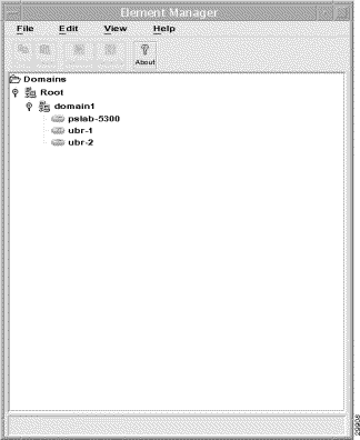
Figure 3-3 shows a sample Cisco IP Manager screen with Cisco uBR7200 series universal broadband router domain and icons.
Cisco Cable Manager also allows you to specify and display the Cisco uBR7200 series universal broadband router configuration parameters for reference. These settings are required to use the Find/Ping modem feature, Flapping Modem report, and can be helpful to establish a Telnet session.
To specify configuration parameters for reference, select the desired Cisco uBR7200 series universal broadband router in an object map and from the right-click menu, select Modify Configuration Settings. The Modify Configuration Settings dialog box appears.
Figure 3-4 shows the Modify Configuration Settings dialog box.
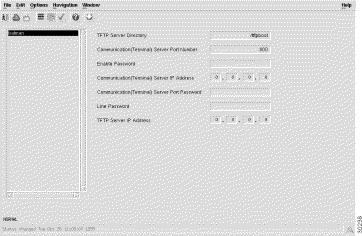
Specify the device settings for later reference and to enable the Find/Ping cable modem and Flapping Modem report features.
Table 3-2 describes fields in the Modify Configuration Settings dialog box.
| Field | Description |
|---|---|
TFTP Server Directory | The default TFTP boot directory. |
Communication (Terminal) Server Port Number | The port number of the communications server used to remotely access the Cisco uBR7200 series universal broadband router. |
Enable Password | The enable password of the Cisco uBR7200 series universal broadband router. This field is required for the Find/Ping cable modem and Flapping Modem report features. |
Communication (Terminal) Server IP Address | The IP address of the communications server used to remotely access the Cisco uBR7200 series universal broadband router. |
Communication (Terminal) Server Port Password | The password used to access the port on the communications server used to remotely access the Cisco uBR7200 series universal broadband router. |
Line Password | The line password of the Cisco uBR7200 series universal broadband router. This field is required for the Find/Ping cable modem and Flapping Modem report features. |
TFTP Server IP Address | The IP address of the TFTP server. |
Cisco Cable Manager provides the following performance capabilities for Cisco uBR7200 series universal broadband routers and cable modems. Report data can be generated for all the routers deployed under a site, individual cable routers or individual cable modem. Report data can be exported in tab-delimited ASCII files. All reports can be run on-demand or on a scheduled basis.
Report data is available in predefined and customized reports. Predefined and customized report data is stored on a daily basis in /opt/AV/performance/[date] directories. If disk space becomes unavailable, these files may need to be archived to another location or deleted.
Predefined reports display a preset group of performance parameters for a selected Cisco uBR7200 series universal broadband router or a group of routers.
The following predefined reports are available for cable router performance:
To display a predefined performance report, select the desired object and from the right-click menu, select uBR Predefined Performance Report. The uBR Predefined Performance Report Date and Time dialog box appears. (See Figure 3-5.)
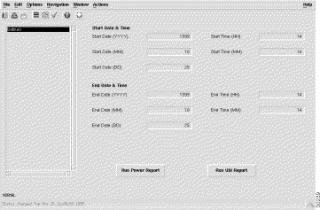
Specify the desired dates and times, click Save (check mark) in the tool bar, and click Run Report for the desired report. The uBR Power Level Report dialog box appears with the selected report data. (See Figure 3-6.)
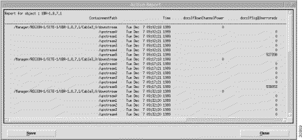
Table 3-3 describes the Power Level report fields.
| Field | Description |
|---|---|
ContainmentPath | Cisco Cable Manager containment levels for the selected device. |
Timestamp | Date and time data was generated. |
docsIfDownChannelPower | At the Cisco uBR7200, the operational transmit power. At the cable modem, the received power level. This value may be zero at the cable modem if power level measurement is not supported. If the interface is down, this value may be either the configured value (Cisco uBR7200), the most current value (cable modem) or 0. |
docsIfSigQUnerroreds | Codewords received on this channel without error. This includes all codewords, whether or not they were part of frames destined for this device. |
docsIfSigQCorrecteds | Codewords received on this channel with correctable errors. This includes all codewords, whether or not they were part of frames destined for this device. |
docsIfSigQUncorrectables | Codewords received on this channel with uncorrectable errors. This includes all codewords, whether or not they were part of frames destined for this device. |
docsIfSigQSignalNoise | Signal/Noise ratio as perceived for this channel. Only meaningful in cable modems. Returns zero for Cable Modem Termination Systems. |
Repeat this procedure for each uBR Predefined Performance Report you wish to run.
Figure 3-7 shows an example uBR Predefined Performance Report for utilization level.
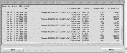
Table 3-4 describes the Utilization Level report the fields:
| Field | Description |
|---|---|
Containment Path | Cisco Cable Manager containment levels for the selected device. |
Timestamp | Date and time data was generated. |
ifInOctets (KB) | Total number of octets received on the interface including framing characters. |
ifInUcast Pkts | Number of delivered packets that were not addressed to a multicast or broadcast address. |
ifInNUcastPkts | Number of delivered packets that were addressed to a multicast or broadcast address. |
inDiscards | Number of inbound packets that were discarded even though no errors were detected to prevent their delivery. Packets may have been discarded to free up buffer space. |
ifInErrors | For packet-oriented interfaces, the number of inbound packets that contained errors that prevented them from being delivered. For character-oriented or fixed-length interfaces, the number of inbound transmission units that contained errors that prevented them from being delivered. |
inUnknownProtos | For packet-oriented interfaces, the number of packets received via the interface discarded because of an unknown or unsupported protocol. For character-oriented or fixed-length interfaces that support protocol multiplexing, the number of transmission units received via the interface discarded because of an unknown or unsupported protocol. For any interface that does not support protocol multiplexing, this counter will always be 0. Discontinuities in the value of this counter can occur at reinitialization of Cisco Cable Manager, and at other system interruptions. |
ifOutOctets | Total number of octets transmitted out of the interface, including framing characters. Discontinuities in the value of this counter can occur at re-initialization of Cisco Cable Manager, and at other system interruptions. |
ifOutUcastPkts | Total number of packets that higher-level protocols requested be transmitted, but were not addressed to a multicast or broadcast address at this sub-layer, including those discarded or not sent. Discontinuities in the value of this counter can occur at reinitialization of Cisco Cable Manager, and at other system interruptions. |
ifOutNUCastPkts | Total number of packets that higher-level protocols requested be transmitted, but were addressed to a multicast or broadcast address at this sub-layer, including those that were discarded or not sent. Discontinuities in the value of this counter can occur at reinitialization of Cisco Cable Manager, and at other system interruptions. |
ifOutDiscards | Number of outbound packets chosen to be discarded even though no errors were detected to prevent their being transmitted. One possible reason for discarding such a packet could be to free up buffer space. Discontinuities in the value of this counter can occur at reinitialization of Cisco Cable Manager, and at other system interruptions. |
ifOutErrors | For packet-oriented interfaces, the number of outbound packets that could not be transmitted because of errors. For character-oriented or fixed-length interfaces, the number of outbound transmission units that could not be transmitted because of errors. Discontinuities in the value of this counter can occur at reinitialization of Cisco Cable Manager, and at other system interruptions. |
ifInMulticastPkts | Number of packets, delivered by this sub-layer to a higher (sub)layer, which were addressed to a multicast address at this sublayer. For a MAC layer protocol, this includes both Group and Functional addresses. Discontinuities in the value of this counter can occur at reinitialization of Cisco Cable Manager, and at other system interruptions. |
ifInBroadcastPkts | Number of packets, delivered by this sublayer to a higher (sub)layer, that were addressed to a broadcast address at this sublayer. Discontinuities in the value of this counter can occur at reinitialization of Cisco Cable Manager, and at other system interruptions. |
ifOutMulticastPkts | Total number of packets that higher-level protocols requested be transmitted, and that were addressed to a multicast address at this sublayer, including those that were discarded or not sent. For a MAC layer protocol, this includes both Group and Functional addresses. Discontinuities in the value of this counter can occur at reinitialization of Cisco Cable Manager, and at other system interruptions. |
ifOutBroadcastPkts | Total number of packets that higher-level protocols requested be transmitted, and that were addressed to a broadcast address at this sublayer, including those that were discarded or not sent. Discontinuities in the value of this counter can occur at reinitialization of Cisco Cable Manager, and at other system interruptions. |
Customized reports allow you to select a parameter from a list of available performance parameters and display data for the selected parameter. Data can be displayed for a selected Cisco uBR7200 series universal broadband router or for a group of routers by selecting a higher level. The following customized reports are available:
To display a customized performance report, select the desired cable router and from the right-click menu, select Open UBR Customized Report. The Customized Report dialog box appears with the selected report data.
Figure 3-8 shows the uBR Customized Performance Report. Data for the selected attribute appears in the display area. Select the type of data to be displayed from the list of monitored attributes. Use the three tabs at the top of the display area to specify the desired display format.
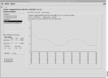
Table 3-5 summarizes the customized report parameters that are available for cable router performance.
| Field | Description |
|---|---|
ciscoMemoryPoolLargestFree | Largest number of contiguous bytes from the memory pool that are currently unused on the managed device. |
ciscoMemoryPoolFree | Number of bytes from the memory pool that are currently unused on the managed device. |
ciscoMemory Pool Used | Number of bytes from the memory pool that are currently in use by applications on the managed device. |
busyPer | Cumulative CPU usage percentage. |
avgBusy1 | Cumulative average of the CPU usage percentage over a 1-minute period. This variable, called by the scheduler every 5 seconds, computes the busy time in the last 5-second period, and the 5-minute exponentially delayed busy time. |
avgBusy5 | Cumulative average of the CPU usage percentage over a 5-minute period. This variable, called by the scheduler every 5 seconds, computes the busy time in the last 5-second period, and the 5-minute exponentially delayed busy time. |
To display a customized performance report, select the desired RF line card and from the right-click menu, select Open RF Line Card Customized Report. The Customized Report dialog box appears with the selected report data.
Figure 3-9 shows the RF Line Card Customized Performance Report. Data for the selected attribute appears in the display area. Select the type of data to be displayed from the list of monitored attributes. Use the three tabs at the top of the display area to specify the desired display format.
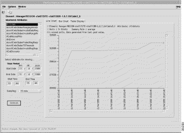
Table 3-6 summarizes the customized report parameters that are available for RF line card performance.
| Field | Description |
|---|---|
ifSpeed | Interface's current bandwidth in bits per second. |
docsIfCmtsStatusInvalidRegReqs | Invalid registration requests received on this interface. |
ifInOctets | Total number of octets received on the interface, including framing characters. |
ifInDiscards | Number of inbound packets discarded even though no errors were detected. One possible reason for discarding a packet may be to free up buffer space. |
ifInNUcastPkts | Number of packets delivered to a multicast or broadcast address. |
docsIfCmtsStatusRangingAborteds | Ranging attempts that were explicitly aborted by the Cisco uBR7200 series universal broadband router. |
ifOutUcastPkts | Total number of packets requested be transmitted which were not addressed to a multicast or broadcast address, including packets that were discarded or not sent. |
ifOutNUcastPkts | Total number of packets transmitted to a multicast or broadcast address, including packets that were discarded or not sent. |
docsIfCmtsStatusInvalidRangeReqs | Invalid range requests received on this interface. |
docsIfCmtsStatusT5Timeouts | Number of times counter T5 expired on this interface. |
ifInUnknownProtos | For packet-oriented interfaces, the number of packets which were discarded because of an unknown or unsupported protocol. For character-oriented or fixed-length interfaces that support protocol multiplexing the number of transmission units received that were discarded because of an unknown or unsupported protocol. For any interface that does not support protocol multiplexing, this counter will always be 0. |
ifInUcastPkts | Number of packets that were not addressed to a multicast or broadcast address. |
docsIfCmtsStatusInvalidDataReq | Invalid data requests received on this interface. |
docsIfCmtsStatusFailedRegReqs | Failed registration attempts (authentication failures and class of service failures) on this interface. |
ifOutOctets | Total number of octets transmitted, including framing characters. |
ifOutDiscards | Number of outbound packets discarded even though no errors had been detected to prevent their being transmitted. One possible reason for discarding such a packet may be to free up buffer space. |
ifOutErrors | For packet-oriented interfaces, the number of outbound packets that could not be transmitted because of errors. For character-oriented or fixed-length interfaces, the number of outbound transmission units that could not be transmitted because of errors. |
ifInErrors | For packet-oriented interfaces, the number of inbound packets that contained errors preventing them from being delivered. For character-oriented or fixed-length interfaces, the number of inbound transmission units that contained errors preventing them from being delivered |
To display a customized performance report, select the desired downstream channel and from the right-click menu, select Open Downstream Customized Report. The Customized Report dialog box appears with the selected report data.
Figure 3-10 shows the Downstream Customized Performance Report. Data for the selected attribute appears in the display area. Select the type of data to be displayed from the list of monitored attributes. Use the three tabs at the top of the display area to specify the desired display format.
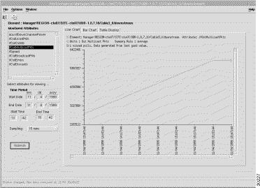
Table 3-7 summarizes the customized report parameters that are available for cable router performance.
| Field | Description |
|---|---|
ifOutUcastPkts | Total number of packets requested to be transmitted that were not addressed to a multicast or broadcast address, including packets that were discarded or not sent. |
ifOutErrors | For packet-oriented interfaces, the number of outbound packets that could not be transmitted because of errors. For character-oriented or fixed-length interfaces, the number of outbound transmission units that could not be transmitted because of errors. |
ifOutMulticastPkts | Total number of packets requested to be transmitted that were addressed to a multicast address, including those discarded or not sent. For a MAC-layer protocol, this includes both group and functional addresses. |
ifOutDiscards | Number of outbound packets discarded even though no errors had been detected to prevent their being transmitted. One possible reason for discarding such a packet may be to free up buffer space. |
ifOutBroadcastsPkts | Total number of packets requested to be transmitted and addressed to a broadcast address, including packets discarded or not sent. |
ifSpeed | Estimate of the interface's current bandwidth in bits per second. |
docsIfDownchannelPower | At the Cisco uBR7200 series universal broadband router, the operational transmit power. At the cable modem, the received power level or zero if power level measurement is not supported. If the interface is down, the configured value for Cisco uBR7200 series universal broadband router value, the most current value for cable modem, or 0. |
ifOutOctets | Total number of octets transmitted, including framing characters. |
To display a customized performance report, select the desired upstream channel and from the right-click menu, select Open Upstream Customized Report. The Customized Report dialog box appears with the selected report data.
Figure 3-11 shows the Upstream Customized Performance Report. Data for the selected attribute appears in the display area. Select the type of data to be displayed from the list of monitored attributes. Use the three tabs at the top of the display area to specify the desired display format.
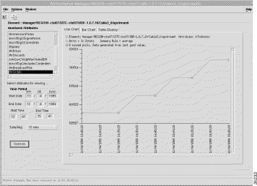
Table 3-8 summarizes the customized report parameters that are available for upstream channel performance.
| Field | Description |
|---|---|
ifSpeed | The interface's current bandwidth in bits per second. |
cdxQosCtrlUpReservedBW | The current total reserved bandwidth in bits per second of this upstream interface. It is the sum of all cable modems' minimum guaranteed bandwidth in bits per second currently supported on this upstream. |
ifInDiscards | Number of inbound packets that were discarded even though no errors had been detected to prevent delivery to a higher-layer protocol. One possible reason for discarding such a packet could be to free up buffer space. Discontinuities in the value of this counter can occur at reinitialization of the management system, and at other times. |
docsIfSigQUnerroreds | Codewords received on this channel without error. This includes all codewords, whether or not they were part of frames destined for this device. |
ifInUcastPkts | Number of packets, delivered by this sublayer to a higher (sub)layer, that were not addressed to a multicast or broadcast address at this sublayer. Discontinuities in the value of this counter can occur at reinitialization of the management system, and at other times. |
ifInOctets | Total number of octets received on the interface, including framing characters. |
cdxQosCtrlUpAdmissionRejects | Number of cable modem registration requests rejected on this upstream interface due to insufficient reserved bandwidth for serving the cable modem with minimum guaranteed bandwidth in its Quality of Service class. |
ifInErrors | For packet-oriented interfaces, the number of inbound packets that contained errors preventing them from being delivered. For character-oriented or fixed-length interfaces, the number of inbound transmission units that contained errors preventing them from being delivered |
docsIfSigQIncludesContention | True (1) indicates the Cisco uBR7200 series universal broadband router includes contention intervals in the counters in this table. |
ifInBroadcastsPkts | The number of packets delivered to a broadcast address. |
cdxQosCtrlUpMaxVirtualBW | Maximum virtual bandwidth capacity of this upstream interface if the admission control is enabled. It is the raw bandwidth in bits per second times the percentage. If the admission control is disabled, then this value is zero. |
ifInUnknownProtos | For packet-oriented interfaces, the number of packets discarded because of an unknown or unsupported protocol. For character-oriented or fixed-length interfaces that support protocol multiplexing, the number of transmission units received that were discarded because of an unknown or unsupported protocol. For any interface that does not support protocol multiplexing, this counter will always be 0. |
docsIfSigQUncorrectables | Code words were received on this channel with uncorrectable errors. This includes all code words, whether or not they were part of frames destined for this device. |
docsIfSigQSignalNoise | Signal/noise ratio for this channel. |
ifInMulticastPkts | Number of packets delivered to a multicast address. For a MAC layer protocol, this includes both group and functional addresses. |
docsifSigQCorrecteds | Code words received on this channel with correctable errors. This includes all code words, whether or not they were part of frames destined for this device. |
docsIfSigQMicroreflections | Rough estimate of the total microreflections including in-channel response on this interface, measured in dBc below the signal level. |
To display a customized performance report, select the desired port adapter and from the right-click menu, select Open Port Adapter Customized Report. The Customized Report dialog box appears with the selected report data.
Figure 3-12 shows the Port Adapter Customized Performance Report. Data for the selected attribute appears in the display area. Select the type of data to be displayed from the list of monitored attributes. Use the three tabs at the top of the display area to specify the desired display format.
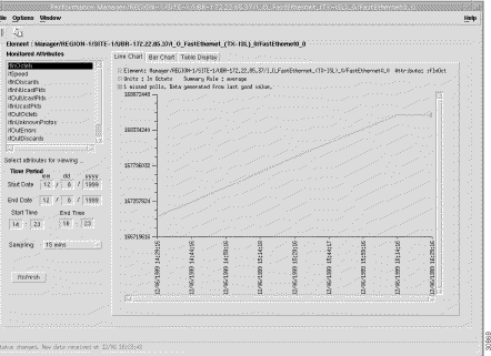
Table 3-9 summarizes the customized report parameters that are available for port adapter performance.
| Field | Description |
|---|---|
ifOutNUcastPkts | Total number of packets requested to be transmitted that were not addressed to a multicast or broadcast address, including packets that were discarded or not sent. |
ifInErrors | For packet-oriented interfaces, the number of inbound packets that contained errors preventing them from being delivered. For character-oriented or fixed-length interfaces, the number of inbound transmission units that contained errors preventing them from being delivered |
ifOutDiscards | Number of outbound packets discarded even though no errors had been detected to prevent their being transmitted. One possible reason for discarding such a packet may be to free up buffer space. |
ifSpeed | Estimate of the interface's current bandwidth in bits per second. |
ifInOctets | Total number of octets received on the interface, including framing characters. |
ifInNUcastPkts | Number of packets, delivered to a multicast or broadcast address. |
ifnUnknownProtos | For packet-oriented interfaces, the number of packets discarded because of an unknown or unsupported protocol. For character-oriented or fixed-length interfaces that support protocol multiplexing the number of transmission units received that were discarded because of an unknown or unsupported protocol. For any interface that does not support protocol multiplexing, this counter will always be 0. |
ifInUcastPkts | Number of packets that were not addressed to a multicast or broadcast address. |
ifInDiscards | Number of inbound packets discarded even though no errors were detected. One possible reason for discarding a packet may be to free up buffer space. |
ifOutOctets | Total number of octets transmitted, including framing characters. |
ifOutUcastPkts | Total number of packets requested to be transmitted that were not addressed to a multicast or broadcast address, including packets that were discarded or not sent. |
ifOutErrors | For packet-oriented interfaces, the number of outbound packets that could not be transmitted because of errors. For character-oriented or fixed-length interfaces, the number of outbound transmission units that could not be transmitted because of errors. |
Cisco Cable Manager allows you to purge report data to avoid data storage limitations. Predefined and customized report data is stored on a daily basis in /opt/AV/performance/[date] directories. If disk space becomes unavailable, these files may need to be archived to another location or deleted.
Cisco Cable Manager allows you to save report data. To save report data, click Save. Cisco Cable Manager saves the report data in a tab-delimited ASCII file in the specified directory.
Cisco Cable Manager allows you to schedule when a reports is run. To schedule a report to run sometime in the future, click Run Report and specify the desired date and time.
Cisco Cable Manager allows you to display inventory reports to manage the currently deployed Cisco uBR7200 series universal broadband routers. Inventory reports include the Cisco IOS releases of Cisco uBR7200 series universal broadband routers and cable modems along with data for the installed cable line cards, port adapters, upstream channels, and downstream channels.
To display an inventory report, select the desired Cisco uBR7200 series universal broadband router in a Map View or Object Tree and from the right-click menu, select UBR Inventory Report. The Inventory Report window appears with tabs for card information and environment data. Figure 3-13 shows an inventory report with card information.
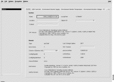
Table 3-10 describes the uBR Inventory Report dialog box data.
| Field | Description |
|---|---|
Name | Administratively-assigned name for this device. By convention, this is the device's fully-qualified domain name. |
SysUpTime | Time (in hundredths of a second) since the system was last reinitialized. |
Location | Administratively-assigned physical location of this node (for example, telephone closet, third floor). |
Object-ID | The vendor's authoritative identification of the network management subsystem contained in the entity. This value is allocated within the SMI enterprises subtree (1.3.6.1.4.1) and provides an easy and unambiguous means for determining what kind of box is being managed. For example, if vendor Flintstones, Inc. was assigned the subtree 1.3.6.1.4.1.4242, it could assign the identifier 1.3.6.1.4.1.4242.1.1 to its "Fred Router." |
Contact | Administratively-assigned contact information for this managed node. |
SWversion | Cisco IOS release information. |
Type | Type of device, such as Cisco uBR7246. |
Last Change | Time when the interface entered its current operational state. |
Uptime | Time (in hundredths of a second) since the Cisco Cable Manager the system was reinitialized. |
No of Slots | Number of slots in this chassis or -1 if not applicable or undeterminable. |
Hw version | Chassis hardware revision level, or blank if unavailable. |
Chassis -ID (serial no) | The unique ID string. Defaults to chassis serial number if available, otherwise blank. |
ProcessorRAM | Bytes of RAM available to CPU. |
ConfigRegister | Value of configuration register. |
NVRAMsize | Bytes of nonvolatile configuration memory. |
ConfigRegisterNext | Value of configuration register at next reload. |
NVRAMUsed | Bytes of nonvolatile configuration memory in use. |
Chassis Partner | Used to determine if this is a partner variant of a product. |
romversion | ROM monitor version. |
romSysVersion | ROM system software version, or blank if unavailable. |
| Field | Description |
|---|---|
CardType | Functional type of this card. |
CardDescr | Administratively-assigned text description of this card. |
CardSerial | Serial number of this card, or zero if unavailable. |
HW-Version | Hardware revision level of this card or blank if unavailable. |
SW-Version | Version of the firmware or microcode installed on this card or blank if unavailable. |
SlotNumber | Slot number relative to the containing card or chassis, or -1 if not applicable or undeterminable. |
OperStatus | The operational status of the card. Up indicates a card is recognized by the device and is enabled for operation. Down indicates the card is not recognized by the device, or it is not enabled for operation. Standby indicates the card is enabled and acting as a standby slave. |
Card Slots | Number of slots on this card, 0 if no slots or not applicable, or -1 if undeterminable. |
| Field | Description |
|---|---|
Power Supply (Description) | Textual description of the power supply. |
Power-Supply (CurrentState) | The current state of the power supply. |
| Field | Description |
|---|---|
Description | Textual description of the temperature status. |
Current Value (TempStatus) | Current temperature. |
Highest-Value (TempStatus) | Highest temperature recorded. |
Status-Value (LastShutDown) | Temperature at the time of an emergency shutdown of the managed device. This value is stored in non-volatile RAM and is therefore able to survive the shutdown. |
Current-State | The current operational state of the device. |
| Field | Description |
|---|---|
Description | Textual description of the voltage status. |
Current Value (Voltage Status) | Current voltage. |
Lowest Value (Voltage Status) | Highest voltage recorded. |
Highest-Value (VoltageStatus) | Lowest voltage recorded. |
Status Value (LastShutDown) | Voltage at the time of an emergency shutdown of the managed device. This value is stored in nonvolatile RAM and hence is able to survive the shutdown. |
Current-State | Current voltage state. |
| Field | Description |
|---|---|
Device-Size | Size of the Flash device. |
Device-Name | Name of the device within the system. Flash operations get directed to a device based on this name. The system has a concept of a default device. This would be the primary or most used device in case of multiple devices. The system directs an operation to the default device whenever a device name is not specified. The device name is therefore mandatory except when the operation is being done on the default device or the system supports only a single Flash device. The device name will always be available for a removable device, even when the device has been removed. |
Description | Description of a Flash device. The description is meant to explain of the Flash device and its purpose. Current values are: |
DeviceRemovable | Indicates whether the Flash device is removable. Generally, only PCMCIA Flash cards are removable. Socketed Flashchips and Flash SIMM modules are not removable. Simply put, only those Flash devices that can be inserted or removed without opening the hardware casing are considered removable. Further, removable Flash devices are expected to have the necessary hardware support: On-line removal and insertion and Interrupt generation on removal or insertion. |
| Field | Description |
|---|---|
File Size | Size of the file in bytes. This size does not include the size of the file system file header. |
Checksum | File checksum stored in the file header. This checksum is computed and stored when the file is written into Flash. It serves to validate the data written into Flash. |
File Status | Current status of the file. A file is marked as having an invalid checksum if any checksum mismatch was detected while writing or reading the file. Incomplete files (files truncated either because of lack of free space, or a network download failure) are also written with a bad checksum and marked as invalid. |
File Name | Flash file name as specified by the user copying in the file. The name should not include the colon (:) character as it is a special separator character used to delineate the device name, partition name, and the file name. |
| Field | Description |
|---|---|
Pool Type | Represents the different types of memory pools that may be present in a managed device. Memory pools can be roughly categorized into two groups, predefined pools and dynamic pools. The following pool types are currently predefined:
The processor pool is required to be supported by all devices. Support for other pool types is dependent on the device being managed. |
Name | A textual name assigned to the memory pool. |
Alternate | Indicates whether or not this memory pool has an alternate pool configured. Alternate pools are used for fallback when the current pool runs out of memory. If this value is zero, this pool does not have an alternate. |
Valid | Indicates whether or not the other fields contain accurate data. A value of false indicates an internal error condition and the other fields may contain inaccurate information (specifically, the reported values may be less than the actual values). |
Used | Indicates the number of bytes from the memory pool currently in use by applications on the managed device. |
Free | Indicates the number of bytes from the memory pool currently unused on the managed device. The sum of bytes in the Used pool and the bytes in the Free pool equals the total amount of memory in the pool. |
You can use Cisco Cable Manager to perform the following cable modem management:
You can use Cisco Cable Manager to download Cisco IOS software images to a single cable modem or all registered cable modems associated with a specific upstream channel. The download cable modem software features is supported for Cisco uBR904, Cisco uBR924, and select Cisco partner cable modems that are DOCSIS 1.0 compliant.
One or a set of cable modems can be upgraded to a new software image and then reset/rebooted. The software download feature can be triggered on an on-demand or scheduled basis.
To download software to a cable modem(s), select the desired Cisco uBR7200 series universal broadband router, line card, or upstream channel that contains the desired cable modes or select an individual cable modem. From the right-click menu, select Open SW Download --- Cable Modem. The Software Download dialog box appears. Select the desired cable modem(s) and specified the desired settings. Click Initiate Software Download. In the Scheduler box, either click OK to perform the download or enter the desired date and time to perform the download at the specified period.
Figure 3-14 shows the Software Download dialog box.
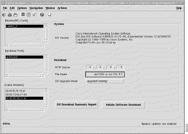
Table 3-18 describes the Software Download dialog box fields.
| Field | Description |
|---|---|
Modems (RF) Cards | Lists the cable modems. |
Upstream Ports | Lists the upstream connections to the current Cisco uBR7200 series universal broadband router. |
Cable Modem | Lists the cable modems connected to the current Cisco uBR7200 series universal broadband router. When mult-selecting cable modems, ensure all the selected modesm are of the same type and can use the specified TFTP server and file. Cable modems of different types will not receive the downloaded file. |
System | Current Cisco IOS image information for the selected cable modem(s). |
TFTP Server | IP address of the TFTP server used by the selected cable modem(s). |
File Name | Cisco IOS image name to be downloaded to the selected cable modem(s). |
SW Upgrade Mode | Mode used to download software images and then reboot the cable modem after the image is downloaded. |
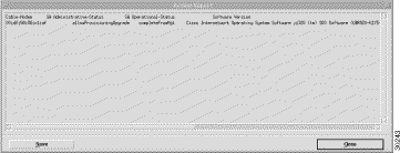
From this dialog box, Cisco Cable Manager allows you to display a software download summary report.
To display the software download summary report, click SW Download Summary Report.
Figure 3-15 shows the Download Software Summary Report dialog box.
 t
t
Cisco Cable Manager provides performance report capabilities for cable modems. Report data can be generated for the cable modems assigned to a Cisco uBR7200 series universal broadband router or individual cable modems. Report data can be exported in tab-delimited ASCII files.
Report data is available in predefined and customized reports. Predefined and customized report data is stored on a daily basis in /opt/AV/performance/[date] directories. If disk space becomes unavailable, these files may need to be archived to another location or deleted.
Cisco Cable Manager provides predefined cable modem performance reports to display a selected group of performance parameters for a selected cable modem or a group of cable modems.
The following predefined reports and parameters are available:
To display a cable modem predefined performance report, select the desired object that contains the cable modem(s) and from the right-click menu, select Open CM Predefined Performance Report. The date/time dialog box appears.
Figure 3-16 shows the Cable Modem Predefined Performance Report Date and Time dialog box.
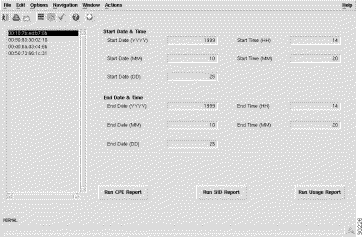
Enter the desired date/time intervals, click Save in the toolbar, and click Run Report. The CM Predefined Performance Report dialog box appears.
Figure 3-17 shows the CM Predefined Performance Report dialog box.
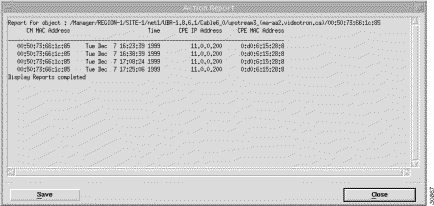
Table 3-19 describes the Cable Modem CPE Predefined report data.
| Field | Description |
|---|---|
Cable modem MAC address | Unique machine address of the cable modem. |
Timestamp | Date and time of the current report. |
CPE IP address | IP address(es) of the customer-provided equipment connected to the cable modem. |
CPE MAC address | Unique machine address(es) of the customer-provided equipment connected to the cable modem. |
Figure 3-18 shows the cable modem SID Predefined Performance Report dialog box.
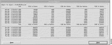
Table 3-20 describes the Cable Modem SID Predefined report data.
| Field | Description |
|---|---|
Cable modem MAC address | Unique machine address of the cable modem. |
Timestamp | Date and time of the current report. |
docsIfCmtsServiceInOctets | Total number of octets received on the interface, including framing characters. |
docsIfCmtsServiceInPackets | Total number of packets received on the interface, including framing characters. |
cdxIfCmtsServiceOutOctets | Total number of octets transmitted on the interface, including framing characters. |
cdxIfCmtsServiceOutPackets | Total number of packets transmitted on the interface, including framing characters. |
Figure 3-19 shows the cable modem usage Predefined Performance Report dialog box.
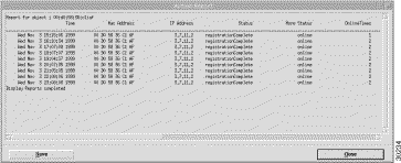
Table 3-21 describes the Cable Modem Usage report data.
| Field | Description |
|---|---|
MAC address | Unique machine address of the cable modem. |
Timestamp | Date and time data was generated. |
Status index | An unique identifier this cable modem. This value should not change during CMTS uptime. |
IP address | IP address assigned to the cable modem. |
statusdownChannelIfIndex | Current status of the registration process. |
statusUpChannelIfIndex | Additional registration status information. |
docsIfCmtsCmStatusRxPower | Receive power for upstream data from this cable modem. A value of zero indicates the receive power is unknown. |
docsIfCmStatusValue | Current Cable Modem connectivity state: |
cdxIfCmtsCmStatusOnlineTimes | Number of times the modem changes the connectivity state from offline to online over the time period from the modem's first ranging message received by CMTS until now. |
cdxIfCmtsCmStatusPercentOnline | Percentage of time the modem stays online over the time period from the modem's first ranging message received by CMTS until now. The value for this object is 100 times bigger than the real percentage value. For example, 32.15% will be value 3215. |
cdxIfCmtsCmStatusMinOnlineTime | Minimum period of time the modem stayed online over the time period from the modem's first ranging message received by CMTS until now. |
cdxIfCmtsCmStatusAvgOnlineTime | Average period of time the modem stayed online over the time period from the modem's first ranging message received by CMTS until now. |
cdxIfCmtsCmStatusMaxOnlineTime | Maximum period of time the modem stayed online over the time period from the modem's first ranging message received by CMTS until now. |
cdxIfCmtsCmStatusMinOfflineTime | Minimum period of time the modem stayed offline over the time period from the modem's first ranging message received by CMTS until now. |
cdxIfCmtsCmStatusAvgOfflineTime | Average period of time the modem stayed offline over the time period from the modem's first ranging message received by CMTS until now. |
cdxIfCmtsCmStatusMaxOfflineTime | Maximum period of time the modem stayed offline over the time period from the modem's first ranging message received by CMTS until now. |
docsIfCmStatusTxPower | Transmit power for upstream data from this Cable Modem. A value of zero indicates the transmit power is unknown. |
docsIfSigQUnerroreds | Codewords received on this channel without error. This includes all codewords, whether or not they were part of frames destined for this device. |
docsIfSigQCorrecteds | Codewords received on this channel with correctable errors. This includes all codewords, whether or not they were part of frames destined for this device. |
docsIfSigQUncorrectables | Codewords received on this channel with uncorrectable errors. This includes all codewords, whether or not they were part of frames destined for this device. |
docsIfSigQSignalNoise | Signal/Noise ratio as perceived for this channel. Only meaningful in Cable Modems. Returns zero for Cable Modem Termination Systems. |
Customized reports allow you to select a parameter from a list of available performance parameters and display data for the selected parameter. Data can be displayed for a selected cable modem or a group of cable modems.
To display a customized performance report for a cable modem, select the desired cable modem object and from the right-click menu, select Open Cable Modem Customized Report. The Customized Cable Modem Report dialog box appears.
Figure 3-20 shows the Cable Modem Customized Report dialog box.
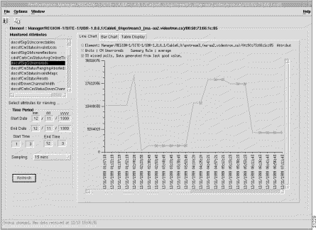
Select the desired object from the Managed Attributes list and enter the desired dates and times. Table 3-22 describes the cable modem performance attributes.
| Field | Description |
|---|---|
docsIfDownChannelId | CMTS identification of the downstream channel within this particular MAC interface. If the interface is down, this is the most current value. If the downstream channel ID is unknown, this is 0. |
docsIfDownChannelPower | At the Cisco uBR7200, the operational transmit power. At the cable modem, the received power level. This value may be zero at the cable modem if power level measurement is not supported. If the interface is down, this value may be either the configured value (Cisco uBR7200), the most current value (cable modem) or 0. |
docsIfDownChannelFrequency | Center of the downstream frequency associated with this channel. This is the current tuner frequency. If a CMTS provides IF output, this value will be 0, unless this CMTS is in control of the final downstream RF frequency. |
docsIfDownChannelWidth | Bandwidth of this downstream channel. Most implementations support a channel width of 6 MHz (North America) and/or 8 MHz (Europe). |
docsIfDownChannelModulation | Modulation type associated with this downstream channel. If the interface is down, this is the configured value (CMTS), the most current value (cable modem), or the value of unknown(1). |
docsIfDownChannelInterleave | Forward Error Correction (FEC) interleaving used for this downstream channel. Values are:
If the interface is down, this object either returns the configured value (CMTS), the most current value (cable modem), or the value of unknown(1). A value of other(2) is returned if the interleave is known but not defined in the above list. |
docsIfCmStatusLostSyncs | Number of times the cable modem lost synchronization with the downstream channel. |
docsIfSigQIncludesContention | True (1) indicates this CMTS includes contention intervals in the counters in this table. Always false (2) for cable modems. |
docsIfSigQUnerroreds | Codewords received on this channel without error. This includes all codewords, whether or not they were part of frames destined for this device. |
docsIfSigQCorrecteds | Codewords received on this channel with correctable errors. This includes all codewords, whether or not they were part of frames destined for this device. |
docsIfSigQUncorrectables | Codewords received on this channel with uncorrectable errors. This includes all codewords, whether or not they were part of frames destined for this device. |
docsIfSigQMicroreflections | Total microreflections including in-channel response as perceived on this interface, measured in dBc below the signal level. This object is not assumed to return an absolutely accurate value, but should give a rough indication of microreflections received on this interface. |
docsIfSigQSignalNoise | Signal/Noise ratio as perceived for this channel. Only meaningful for cable modems. Returns zero for CMTS. |
docsIfCmStatusValue | Current Cable Modem connectivity state, as specified in the RF Interface Specification. |
docsIfCmStatusResets | Number of times the cable modem reset or initialized this interface. |
docsIfCmStatusInvalidMaps | Number of times the cable modem received invalid MAP messages. |
docsIfCmStatusInvalidUcds | Number of times the cable modem received invalid UCD messages. |
docsIfCmStatusInvalidRangingResp | Number of times the cable modem received invalid ranging response messages. |
docsIfCmStatusInvalidRegistrationResp | Number of times the cable modem received invalid registration response messages. |
docsIfCmStatusT1Timeouts | Number of times counter T1 expired in the cable modem. |
docsIfCmStatusT2Timeouts | Number of times counter T2 expired in the cable modem. |
docsIfCmStatusT3Timeouts | Number of times counter T3 expired in the cable modem. |
docsIfCmStatusT4Timeouts | Number of times counter T4 expired in the cable modem. |
docsIfCmStatusTxPower | Operational transmit power for the attached upstream channel. |
docsIfCmStatusRangingAborteds | Number of times the ranging process was aborted by the CMTS. |
Cisco Cable Manager allows to you purge report data to avoid data storage limitations. Predefined and customized report data is stored on a daily basis in /opt/AV/performance/[date] directories. If disk space becomes unavailable, these files may need to be archived to another location or deleted.
Cisco Cable Manager allows you to save report data. To save report data, click Save. Cisco Cable Manager saves the report data in a tab-delimited ASCII file in the specified directory.
Cisco Cable Manager allows you to schedule when a report is run. To schedule a report to run sometime in the future, click Run Report and specify the desired date and time.
Cisco Cable Manager allows you to rehome or reassign cable modems to their master or primary Cisco uBR7200 series universal broadband router after they have been transferred to a secondary Cisco uBR7200 series universal broadband router due to router failover.
To rehome cable modems, select the desired Cisco uBR7200 series universal broadband router that contains the cable modem and from the right-click menu, select Open uBR Cable Modem Rehome. The Cable Modem Rehome dialog box appears.
Figure 3-21 shows the Cable Modem Rehome dialog box.
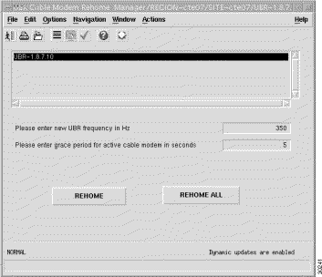
UBR-frequency is the downstream Radio Frequency to which the cable modem has to be rehomed.
Grace period for active cable modem is the time period in seconds that online cable modems can stay homed to the current Cisco uBR7200 series universal broadband router before they get rehomed.
Click Rehome and enter a date and time to rehome the modems to the primary Cisco uBR7200 series universal broadband router if the modem is not busy (no active dynamic SID) or a predetermined timeout has expired. The primary or master Cisco uBR7200 series universal broadband router information is be based on the data stored in the LDAP server.
Click Rehome All and enter a date and time to rehome all cable modems under the selected Cisco uBR7200 to the current Cisco uBR7200. This type of rehome moves all the routers without referencing the data stored in the LDAP server.
CiscoView displays the snapshot data and graph data of device-specific performance statistics and statuses. CiscoView currently supports the following real-time status data:
To launch CiscoView, select the desired device in a Map View or Object Tree and from the right-click menu, choose Launch CiscoView. The CiscoView application window appears with a chassis view of the selected device.
This section contains two sections:
Cisco Cable Manager provides the following tools for troubleshooting Cisco uBR7200 series universal broadband routers and cable modems:
Cisco Cable Manager displays a flapping modem list to provide early notification of potential cable modem failure and lost connectivity.
A polled cable modem is considered intermittent or flapping when any of the following occurs:
Figure 3-22 shows the Flapping Modem List dialog box.
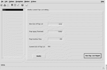
Table 3-23 describes the Flapping Modem List dialog box fields.
| Field | Description |
|---|---|
Max Size of Flap List | Maximum number of cable modems that can appear in the Flap list before the oldest data is overwritten with new data. |
Flap Aging Threshold | Interval in minutes during which the Flap list is refreshed. |
Flap Insertion Time | Timeout period in seconds for the cable modem registration process to complete. If the timeout period is reached before the registration process is complete, the cable modem is added to the Flap list. |
Current Size of Flap List | Number of cable modems currently listed in the Flap list. |
To modify the current Flap List settings, click Modify. To generate a Flap List, click Run Flap-List Report.
To find or ping a cable modem, select the desired group of Cisco uBR7200 universal broadband routers and from the right-click menu, select Find/Ping Cable Modem. The Find/Ping Cable Modem dialog box appears.
Figure 3-23 shows the Find/Ping Cable Modem dialog box.
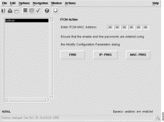
Table 3-24 describes the Find/Ping Cable Modem dialog box fields.
| Field | Description |
Find | Displays the containment path and object location in Cisco Cable Manager. |
IP Ping | Verifies IP network connectivity between the Cisco uBR7200 series universal broadband router and the cable modem. The results are returned to Cisco Cable Manager. |
MAC Ping | Tests the connectivity between Cisco Cable Manager and the specified cable modem. |
To verify Cisco Cable Manager server performance and reliability, use the troubleshooting procedures described in this section.
If available disk space on the Cisco Cable Manager server is low or unavailable, verify that only the desired report data is stored on the server. Predefined and customized report data is stored on a daily basis in /opt/AV/performance/[date] directories. To free disk space, these files may need to be archived to another location or deleted.
This brings up a shell window that has all the necessary Cisco EMF paths set. Run av backup. This command will backup the databases under ${AVROOT}/db and locate them under ${AVROOT}/backup/ with a note on the date on which it was backed up.
To perform a Restore, enter the command av restore. This command prompts for the date in the form of <mm-dd-yyyy> and -d <db1 [db2 ...]> to represent the databases that need to be restored.
The CEMF provides for logging information via log files located under the ${AVROOT}/logs. Of all the log files, the file named cblCtrl.log and cblCtrl.old are of primary importance. These log files are ASCII file that contain all Cisco Cable Manager application specific log messages.
By default, DEBUG entries are not included in these log files. In order to see log messages of DEBUG severity (this includes all other severities), a change needs to be made to the loggercommon.include file located in the /opt/AV/config/init directory. By default the loggingLevelMask is set to 10. Changing this setting to 15 causes all DEBUG level messages to be logged.
The size of the cblCtrl.log file can also be controlled via the cblCtrl.ini file located in the /opt/AV/config/init directory. Add an entry in the logger section of cblCtrl.ini for the size of the log file specified in KBytes. Then stop and re-start CEMF.
An example of a section of the cblCtrl.ini for the logger section in order to specify a 5 MB cblCtrl.log file:
[logger]
#include "loggercommon.include"
loggingName = cblCtrl
maxLogfileSize = 5000
Whenever the cblCtrl.log file reaches it maximum size as specified in the control file, it is archived to a cblCtrl.old file and a new cblCtrl.log file is created.
The numerous other log files also available for troubleshooting. Log files are stored in the /opt/AV/logs directory.
From time to time, it is best to run the script listCores provided in ${AVROOT/bin (typically /opt/AV/bin). This report displays any core files affected by any malfunctioning processes. Whenever an affected core file is seen, please report it to Cisco customer support.
![]()
![]()
![]()
![]()
![]()
![]()
![]()
![]()
Posted: Tue Feb 22 16:36:33 PST 2000
Copyright 1989 - 2000©Cisco Systems Inc.