|
|

This chapter explains how to install the following additional components in your LightStream 2020 enterprise ATM switch:
The procedures in this chapter assume that your LS2020 switch has been operational for some time and that you now wish to install new components in the chassis.
Additional components can be installed in the chassis and become fully operational without rebooting the system or disrupting normal operations. However, installing a switch card may present a special circumstance, as described in the section entitled "Installing Switch Cards."
 | Caution Before adding components to the LS2020 chassis, read the section "Observing Safety Precautions" in the chapter entitled "Installing LightStream 2020 Switch." If you handle components without taking appropriate ESD precautions, damage to the system may result. |
To install an additional switch card, perform the following steps:
Step 1 Remove the front and rear blank filler panels on the LS2020 chassis that correspond to the switch card slot (A or B) into which you intend to install the new switch card.
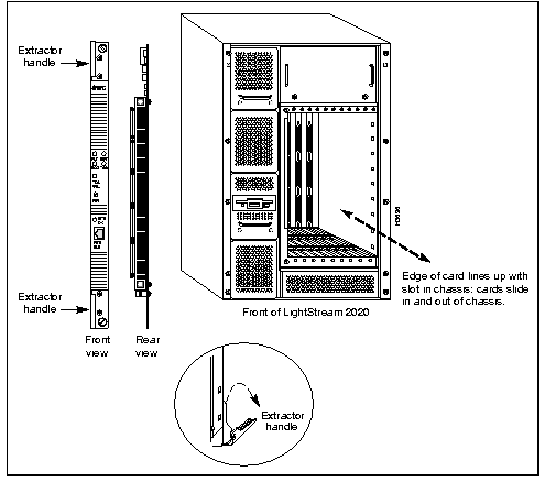
Step 2 Insert the new switch card into the unoccupied slot (A or B) in the front of the LS2020 chassis (see Figure 5-1). Seat the card firmly in the midplane.
Step 3 Lock down the extractor handles on the new switch card and tighten down the screws adjacent to the handles to secure the card in the chassis.
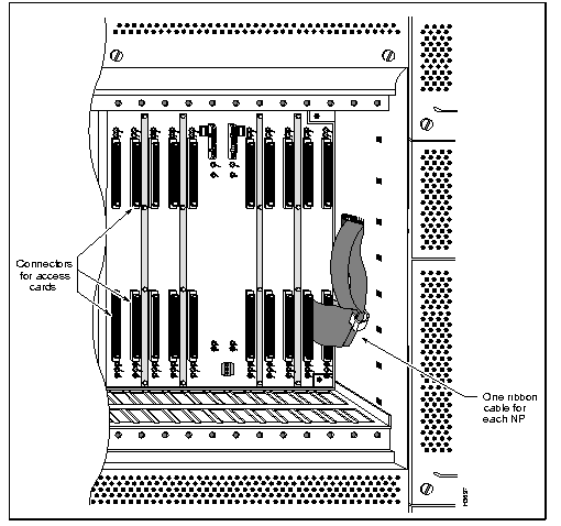
Step 4 To provide sufficient working space within the chassis to attach the free end of the modem/console assembly ribbon cable to its mating connector on the midplane (see Figure 5-2), you may have to temporarily remove one or more adjacent filler panels or access cards from the rear of the chassis.
Make this determination and proceed accordingly. Carefully set aside for the moment any removed filler panels or access cards.
Step 5 Attach the free end of the modem/console assembly ribbon cable to its mating connector on the midplane. Make sure the ribbon cable is firmly seated. Install the modem/console assembly into the appropriate slot in the rear of the chassis directly opposite the new switch card. Secure the modem/console assembly by tightening down the mounting screws.
Step 6 Re-install any filler panels or access cards removed in Step 4.
Step 7 Ensure that flash memory contents of the existing switch card and the newly installed switch card are at the same revision level. Flash memory contains executable code that is essential to proper switch card operation. Thus, flash memory of cards of the same type in an LS2020 chassis must be consistent with each other.
For detailed information about verifying and loading flash memory in a newly installed switch card, refer to the LightStream 2020 Hardware Reference and Troubleshooting Guide.

To install a backup NP module (consisting of an NP card, an NP access card, and a disk assembly), perform the following steps:
Step 1 Remove the front and rear blank filler panels from the slot in the LS2020 chassis into which you intend to install the new NP module.
Step 2 Insert the new NP module into the unoccupied slot (1 or 2) in the left front side of the chassis. Seat the card firmly in the midplane.
Step 3 Lock down the extractor handles on the NP card. Tighten the screws adjacent to the handles to secure the card in the slot.
Step 4 Insert the new access card into the unoccupied slot (1 or 2) in the right rear of the chassis directly opposite the new NP card. Seat the card firmly in the midplane.
Step 5 Lock down the extractor handles on the access card. Tighten the screws adjacent to the handles to secure the access card in the slot.
Step 6 Unscrew and remove the cover panel on the empty disk assembly slot on the left front of the chassis.
Step 7 Slide the new disk assembly into the enclosure. When the connectors pins begin to engage, push gently to avoid pin damage. Firmly seat the disk assembly in place.
Step 8 Tighten the two screws that secure the disk assembly into the chassis.
Step 9 Ensure that the platform software installed on each hard disk is identical.
It is possible, for example, for the new disk assembly you just installed to contain a later version of platform software than you are currently running in your LS2020 chassis. In this instance, you can either install the newer software on the disk for the first NP, or install older software on the new disk for the second NP.
Thus, when installing a backup NP in your LS2020 switch, the only requirement that you must observe is that the platform software on both hard disks be at the same revision level.
See the LightStream 2020 Network Operations Guide for instructions on installing switch software on a disk.
Step 10 Power-up and reactivate the backup NP slot. Refer to the LightStream 2020 Network Operations Guide for instructions regarding this task.
Step 11 Ensure that flash memory contents of the existing NP module and the newly installed NP module are at the same revision level. Flash memory contains executable code that is essential to proper NP operation. Thus, flash memory of cards of the same type in an LS2020 chassis must be consistent with each other.
For detailed information about verifying and loading flash memory in a newly installed NP module, refer to the LightStream 2020 Hardware Reference and Troubleshooting Guide.
Step 12 Install new platform software on the LS2020 hard disk, if necessary. Refer to the LS2020 Network Operations Guide for applicable procedures
Step 13 Follow the instructions in the chapter entitled "Installing LightStream 2020 Switch" to accomplish required basic NP configuration tasks from your NMS.
Step 14 Use the LS-Configurator program to add the new NP module to your LS2020 switch. Load the updated configuration information into the node. See the LightStream 2020 Configuration Guide for applicable information about using the LS-Configurator.
The procedures in this section explain how to install both AC and DC power trays. Figure 2-5 in the chapter entitled "Installing LightStream 2020 Switch" shows the location of power trays at the rear of the LS2020 chassis.
To install a second AC power tray, perform the following steps:
Step 1 Remove the cover panel on the empty power tray slot at the back of the LS2020 chassis.
Step 2 Slide the new power tray into the chassis. Ensure that the power tray seats snugly.
Step 3 Tighten the two screws that secure the power tray assembly to the chassis.
Step 4 Do the following, as appropriate:
Step 5 Turn on system power.
Step 6 Verify that the green LED power indicator is lit.
On power trays equipped with a circuit breaker, the LED is below the switch. On power trays not equipped with a circuit breaker, the LED power indicator is built into the power tray and is visible through the power tray cover.
To install a second DC power tray, you must first accomplish an orderly power shutdown, as described in the following section, "Performing Orderly Shutdown." After doing so, proceed to the section "Power Tray Installation" later in this chapter.
This section explains how to shut down an LS2020 switch gracefully. Two procedures are presented: one for LS2020 switches equipped with two NPs, and one for switches equipped with a single NP.
To shut down a system with two NPs, perform the following steps:
Step 1 Alert anyone who may be affected by a shutdown that you are planning to take the LS2020 system out of service.
Step 2 Log in to the root account on the LS2020 switch you want to shut down.
Step 3 Determine which NP is active (primary) by starting the CLI and issuing the command show chassis general. In the resulting display, look for the entry "Slot of Primary NP." Opposite this entry will be the number "1." This number identifies the NP that you will reboot last.
Step 4 Log into the backup NP (the one whose slot number was not displayed in Step 3 above and do the following:
'. to obtain the TCS hub prompt.
connect <slot#> to connect to the backup NP. (The example below assumes that you are connecting to the NP in slot 2.)
TCS hub<<A>> connect 2
Step 5 From the prompt, enter the following:
bash# reboot -n
Step 6 Enter '. to return to the TCS hub prompt.
Step 7 At the prompt, issue the command connect <slot#> to connect to the primary (active) NP. (The example below assumes that you are connecting to the NP in slot 1.)
TCS hub<<A>> connect 1
Step 8 If necessary, enter the quit command to exit from the CLI and return to the bash# prompt.
Step 9 From the prompt, enter the following:
bash# reboot -n
Step 10 Turn off system power.
To shut down a system with a single NP, perform the following steps:
Step 1 Alert anyone who may be affected by a shutdown that you are planning to take the LS2020 system out of service.
Step 2 Log in to the root account on the switch that you plan to shut down.
Step 3 From the bash# prompt, enter the following:
bash# reboot -n
Step 4 Turn off system power.
To install an additional power tray, perform the following steps:
Step 1 At the back of the LS2020 chassis, unscrew and remove the cover panel on the empty power tray slot.
Step 2 Slide the new power tray into the chassis. Ensure that the power tray seats snugly.
Step 3 Tighten the two mounting screws to secure the power tray assembly to the chassis.
Step 4 Reconnect the power wires and alarm wires (if any) to the terminals on the front of the power tray. (For detailed instructions, see the section "Wiring a DC-Powered System" in the "Installing LightStream 2020 Switch" chapter.)
Step 5 Turn on system power.
Step 6 Verify that the green LED power indicator below the circuit breaker switch on the power tray is lit.
Adding a new interface to an LS2020 switch requires that you install, in matching slots, both a line card in the front of the chassis and an access card in the back of the chassis.
This section describes how to install additional line cards. However, before performing this procedure, note the following installation considerations.
By default, an LS2020 switch is configured on shipment with a disk assembly ribbon cable attached to the rear of the midplane between the bottom connector of slot 2 and the associated disk assembly, whether or not a second disk and NP module are present in the chassis. The location of these disk assembly ribbon cables is illustrated in Figure 5-3.
In a single-NP LS2020 switch, Cisco Systems recommends that you not install an additional line card in slot 2 until all other slots are occupied.
However, if you choose to install an additional line card in slot 2 (either in place of an existing NP module or because all other slots are occupied), you must unplug the disk assembly ribbon cable from the bottom connector and position it between slots 1 and 2 in such a way that it will not interfere with the insertion of the new access card into the midplane.
To install an additional line card into the LS2020 switch, perform the following steps:
Step 1 Remove the front and rear blank filler panels on the LS2020 chassis that correspond to the line card slot(s) into which you intend to install the new switch card(s).
Step 2 Insert the line card(s) into the desired slot in the front of the chassis.
Step 3 Into the corresponding slot(s) at the back of the chassis, insert the associated access card(s) into the midplane and connect all cables, as required, to make appropriate connections to your LS2020 network. The back of the LS2020 chassis provides the necessary facilities for making these connections.
Step 4 Ensure that the contents of flash memory of all line cards in the LS2020 chassis are consistent with each other. Flash memory contains executable code that is essential to proper line card operation. Thus, all cards of the same type in the LS2020 chassis must be at the same revision level.
For detailed instructions about verifying and loading line card flash memory, refer to the LightStream 2020 Hardware Reference and Troubleshooting Guide.
|
|
