|
|

This chapter describes the interconnection facilities for the access cards that you can install in the LightStream 2020 multiservice ATM switch (LS2020 switch). These facilities are described in the following order:
Signal diagrams are provided for the I/O connectors and data cables described in this chapter. Figure 3-1 shows the conventions used in representing the signal paths in these diagrams.

For those interface cables offered for sale by Cisco Systems, a table in the body of each applicable section contains the following information for your convenience:
You can populate the front of an LS2020 chassis with a variety of line cards, depending on your particular communications requirements. Correspondingly, you can populate the opposite slots in the rear of the LS2020 chassis with matching access cards.
Each line card/access card combination in a given slot of an LS2020 chassis constitutes an operational/functional entity referred to as an interface module.
Interface modules support specific kinds of data transfer services in an LS2020 network and provide the means of interconnection and communication among network devices. Each line card is connected to its corresponding access card through the LS2020 chassis midplane.
If you remove an access card from the midplane, service to the corresponding line card is disrupted.
Table 3-1 lists the types of interface modules available for use in an LS2020 switch, together with the applicable line card, associated access card, and the number of ports supported by each module.
| Interface Module Type | Line Card Type | Access Card/Number of ports |
|---|---|---|
Serial modules: First-generation Second-generation1 |
Low-speed card (LSC) Packet line card (PLC) |
Low-speed access card (LSAC) — 8 ports Serial access card (SAC) — 8 ports |
T3/E3 modules: First-generation
Second-generation2 |
Medium-speed card (MSC)
Cell line card (CLC)
|
T3 medium-speed access card (MSAC) — 2 ports E3 G.804 medium-speed access card (MSAC) — 2 ports E3 PLCP medium-speed access card (MSAC) — 2 ports (First-generation T3/E3 cards are no longer orderable) T3 access card (T3AC) — 4 or 8 ports E3 access card (E3AC) — 4 ports |
Constant bit rate (CBR) modules | Packet line card (PLC) | T1 circuit emulation access card (CEMAC-T1) — 8 ports E1 circuit emulation access card (CEMAC-E1) — 8 ports |
OC-3 modules: First-generation
Second-generation
Multimode |
Cell line card (CLC) |
OC-3c single-mode access card equipped with ST connectors (OC3AC-SM) — 1 or 2 ports OC-3c single-mode access card equipped with SC connectors (OC3AC-SM) — 1 or 2 ports OC-3c multimode access card equipped with SC connectors (OC3AC-MM) — 1 or 2 ports |
FDDI module | Packet line card (PLC) | FDDI access card (FAC) — 2 ports |
Ethernet module | Packet line card (PLC) | Ethernet access card (EAC) — 8 ports |
Fiber Ethernet module | Packet line card (PLC) | Fiber Ethernet access card (FEAC) — 8 ports |
1. Upgrade option from first-generation, low-speed access card (LSAC) 2. Upgrade option from first-generation, medium-speed, two-port T3/E3 access cards (MSAC) | ||
This section describes the connectors and cables for the X.21, RS-449, and V.35 interfaces for the serial access cards available for use with the LS2020 switch. Figure 3-2 shows the bulkhead view of these serial interface cards. Such cards are of two types:

The low-speed access card (LSAC) and the serial access card (SAC) use the same types of connectors and cables for hookup. These interconnection facilities are described in the following order:
Figure 3-3 shows the X.21 fantail that you can use with either the low-speed access card (LSAC) or the serial access card (SAC).

Figure 3-4 shows the pin assignments for the eight X.21 interface DB-15 connectors (I/O ports) present on the X.21 fantail.
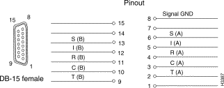
Interface connector type: DB-15 female
Connectors per fantail: eight (numbered 0 to 7)
Figure 3-5 shows the RS-449 fantail that can be used with either the low-speed access card (LSAC) or the serial access card (SAC).
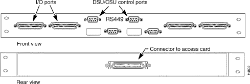
Figure 3-6 shows the pin assignments for the four RS-449 interface DB-37 connectors (I/O ports) present on the RS-449 fantail.
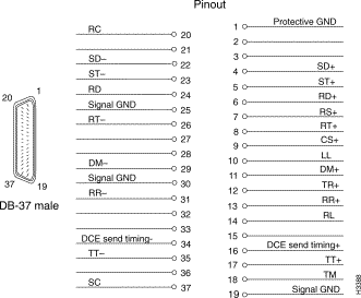
Interface connector type: DB-37 male
Connectors per fantail: four (numbered 0 to 3)
Figure 3-7 shows the V.35 fantail that can be used with either the low-speed access card (LSAC) or the serial access card (SAC).
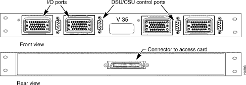
Figure 3-8 illustrates the pin assignments for the four V.35 interface ISO 2593 connectors (I/O ports) present on the V.35 fantail.
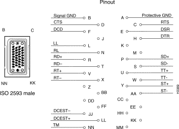
Interface connector type: ISO 2593 male (34-pin block type)
Connectors per fantail: four (numbered 0 to 3)
RS-232 DSU/CSU control ports are present on both the RS-449 and V.35 fantails. If you connect the control port to the craft port on a DSU/CSU device, you can use the csumon program to communicate remotely with the DSU/CSU from an LS2020 switch.
Figure 3-9 shows the pin assignments for the four RS-232 DSU/CSU control ports (DB-9 connectors) present on the RS-449 and V.35 fantail.

Interface connector type: DB-9 male
Connectors per fantail: four (numbered 0 to 3)
This cable incorporates high-density, 100-pin connectors for interconnecting the bulkhead of a low-speed access card (LSAC) or a serial access card (SAC) with the back of an X.21, RS-449, or V.35 fantail.
This fantail cable can be ordered from Cisco Systems in any of three lengths to suit your particular interconnection requirements.
For example, the cable is available in any of three lengths, enabling you to install serial interface fantails in racks adjacent to the one housing the LS2020 chassis and its serial interface cards.
Select the appropriate order number for the fantail cable from the following table.
| Manufacturing No. | Length | Order No. |
72-1117-01 | 4 feet (1.2 m) | L2020-CAB-F4= |
72-1118-01 | 8 feet (2.4 m) | L2020-CAB-F8= |
72-1119-01 | 12 feet (3.6 m) | L2020-CAB-F12= |
Two such data cables are required for the interconnection of an LSAC or SAC bulkhead to the rear of an X.21 fantail: one cable for ports 0 to 3 on the bulkhead, and another cable for ports 4 to 7 on the bulkhead.
Only one such cable is required for the connection of an LSAC or SAC bulkhead to an RS-449 or V.35 fantail.
This cable is used to interconnect an X.21 fantail with an external X.21 device.
The X.21 interface cable can be ordered from Cisco Systems in any of three lengths. Select the appropriate order number from the following table.
| Manufacturing No. | Length | Order No. |
72-0991-01 | 30 feet (9.1 m) | LS-CAB-X21-TC30= |
72-0992-01 | 50 feet (15.2 m) | LS-CAB-X21-TC50= |
72-0993-01 | 100 feet (30.5 m) | LS-CAB-X21-TC100= |
Figure 3-10 is a signal diagram for the X.21 interface cable.
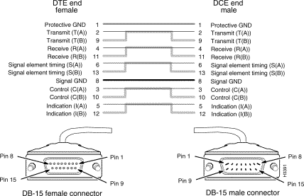
This cable is used to interconnect an RS-449 fantail with an external RS-449 DCE device.
The RS-449 interface straight-through cable can be ordered from Cisco Systems in any of three lengths. Select the appropriate order number from the following table.
| Manufacturing No. | Length | Order No. |
72-1002-01 | 30 feet (9.1 m) | LS-CAB-RS4-TC30= |
72-1003-01 | 50 feet (15.2 m) | LS-CAB-RS4-TC50= |
72-1004-01 | 100 feet (30.5 m) | LS-CAB-RS4-TC100= |
Figure 3-11 is a signal diagram for the RS-449 interface straight-through cable.
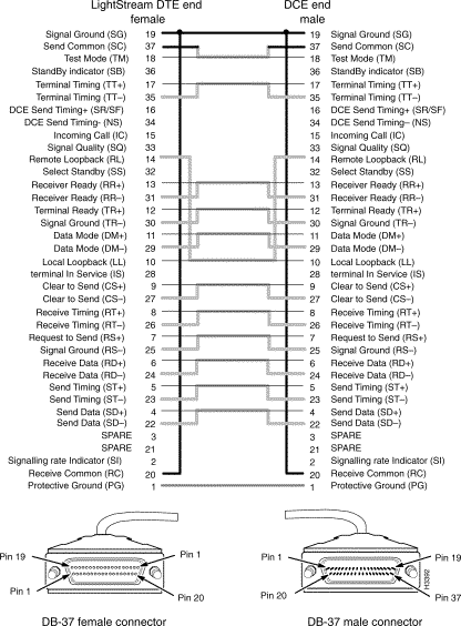
This cable is used to connect two LS2020 switches via their RS-449 fantail interfaces, or to interconnect an RS-449 fantail with an external RS-449 DTE device.
The RS-449 interface crossover cable can be ordered from Cisco Systems in any of four lengths. Select the appropriate order number from the following table.
| Manufacturing No. | Length | Order No. |
72-1008-01 | 8 feet (2.4 m) | LS-CAB-RS4-TT8= |
72-1005-01 | 30 feet (9.1 m) | LS-CAB-RS4-TT30= |
72-1006-01 | 50 feet (15.2 m) | LS-CAB-RS4-TT50= |
72-1007-01 | 100 feet (30.5 m) | LS-CAB-RS4-TT100= |
Figure 3-12 is a signal diagram for the RS-449 interface crossover cable.
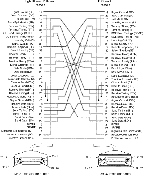
This cable is used to interconnect a V.35 fantail with an external V.35 DCE device.
The V.35 interface straight-through cable can be ordered from Cisco Systems in any of three lengths. Select the appropriate order number from the following table.
| Manufacturing No. | Length | Order No. |
72-1009-01 | 30 feet (9.1 m) | LS-CAB-V35-TC30= |
72-1010-01 | 50 feet (15.2 m) | LS-CAB-V35-TC50= |
72-1011-01 | 100 feet (30.5 m) | LS-CAB-V35-TC100= |
Figure 3-13 is a signal diagram for the V.35 interface straight-through cable.
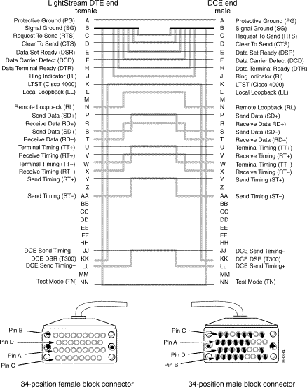
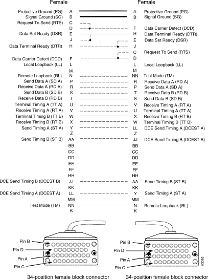
This cable is used to connect two LS2020 switches via their V.35 fantail interfaces, or to interconnect a V.35 fantail with an external V.35 DTE device.
The V.35 interface crossover cable can be ordered from Cisco Systems in any of four lengths. Select the appropriate order number from the following table.
| Manufacturing No. | Length | Order No. |
72-0997-01 | 8 feet (2.4 m) | LS-CAB-V35-TT8= |
72-0994-01 | 30 feet (9.1 m) | LS-CAB-V35-TT30= |
72-0995-01 | 50 feet (15.2 m) | LS-CAB-V35-TT50= |
72-0996-01 | 100 feet (30.5 m) | LS-CAB-V35-TT100= |
Figure 3-14 is a signal diagram for the V.35 interface crossover cable.
This section describes the connectors and cables for the T3/E3 access cards. These facilities are discussed in the following order:
Figure 3-15 shows the T3/E3, two-port medium-speed access card (MSAC). The MSAC is a first-generation card that is available in three versions:
Although three different versions of the MSAC are available, the bulkheads of these cards are identical in appearance (see Figure 3-15) and use the same cables for interconnection purposes.

Interface connector type: 75-ohm coaxial BNC jack
Connectors per MSAC card: four (two receive channels and two transmit channels)
Figure 3-16 shows the coaxial cable available for making external device connections for 75-ohm T3/E3 interface applications.

The 75-ohm coaxial cable can be used for the following purposes:
As is the case with the serial (X.21, RS-449, V.35) fantail cables, the 75-ohm coaxial cable for T3/E3 applications can be ordered from Cisco Systems in any of several lengths, allowing considerable latitude in making appropriate connections.
Select the appropriate order number from the following table.
| Manufacturing No. | Length | Order No. |
72-0998-01 | 3 feet (0.9 m) | LS-CAB-T3-CX3= |
72-0399-01 | 25 feet (7.6 m) | LS-CAB-T3-CX25= |
72-1000-01 | 50 feet (15.2 m) | LS-CAB-T3-CX50= |
72-1001-01 | 100 feet (30.5 m) | LS-CAB-T3-CX100= |
Figure 3-17 shows the T3/E3 access cards (T3AC/E3AC). These are second-generation ATM interfaces that operate in conjunction with cell line cards (CLCs).
The T3 access cards are available in either 4-port or 8-port versions, while the E3 access card is available only in a 4-port version, as shown in Figure 3-17.

Figure 3-18 shows the T3/E3 fantail (dressing panel), together with a cable harness that has been assembled into the T3/E3 fantail. The end of the cable harness that attaches to the fantail proper contains 16 BNC connectors for 75-ohm hookup to external devices. The other end of the cable harness connects directly to the SMZ connectors on the bulkhead of a T3AC or E3AC access card.
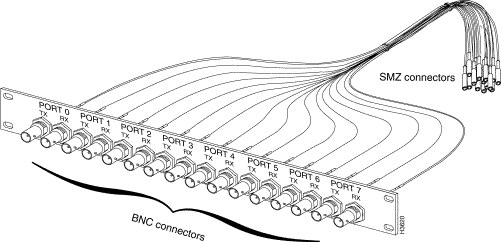
Interface connector type: SMZ connectors on the access card bulkhead; BNC connectors on the T3/E3 fantail proper (see Figure 3-18).
Connectors per access card: 8 or 16 SMZ connectors on the access card bulkhead, depending on the number of ports on the card (either 4 or 8). Each port has one receive (RX) connector and one transmit (TX) connector.
The T3/E3 fantail (dressing panel) and the T3/E3 cable harnesses are available as separate items for interconnecting patch panels or T3/E3 fantails to T3AC or E3AC access cards.
Use the following table for ordering information for the T3/E3 fantail (dressing panel).
| Manufacturing No. | Order No. |
700-00605-01 | LS2020-T3E3-FT= |
The T3 cable harness can be ordered from Cisco Systems in any of three lengths for the 4-port or 8-port version of the T3AC access card. A choice in cable length enables you to install T3/E3 fantails in a rack adjacent to the one housing the LS2020 chassis and associated T3AC access cards, or any other such arrangement that meets your T3 application requirements.
Use the following table for ordering information for the T3 cable harness.
| Manufacturing No. | Ports | Length | Order No. |
72-1097-01 | 4 | 4 feet (1.2 m) | LS-CAB-4T3-4B= |
72-1098-01 | 4 | 8 feet (2.4 m) | LS-CAB-4T3-8B= |
72-1099-01 | 4 | 12 feet (3.6 m) | LS-CAB-4T3-12B= |
72-1061-01 | 8 | 4 feet (1.2 m) | LS-CAB-8T3-4B= |
72-1062-01 | 8 | 8 feet (2.4 m) | LS-CAB-8T3-8B= |
72-1063-01 | 8 | 12 feet (3.6 m) | LS-CAB-8T3-12B= |
Likewise, the E3 cable harness can be ordered from Cisco Systems in any of three lengths for the 4-port E3AC access card.
Use the following table for ordering information for the E3 cable harness.
| Manufacturing No. | Ports | Length | Order No. |
72-1097-01 | 4 | 4 feet (1.2 m) | LS-CAB-4E3-4B= |
72-1098-01 | 4 | 8 feet (2.4 m) | LS-CAB-4E3-8B= |
72-1099-01 | 4 | 12 feet (3.6 m) | LS-CAB-4E3-12B= |
The circuit emulation access card (CEMAC) is available in two versions:
Figure 3-19 shows the bulkhead views of the T1 and E1 CEMAC cards. These cards are identical in appearance, except for the identifying "T1" or "E1" nomenclature at the bottom of the bulkhead.
The E1 CEMAC contains user-settable, on-board jumpers that are configured initially at the factory for 120-ohm operation without a fantail.
If you wish to configure the E1 CEMAC for 75-ohm operation with an E1 fantail, you must set these on-board jumpers accordingly. For detailed information about setting these jumpers, see the LightStream 2020 Hardware Reference & Troubleshooting Guide.

Figure 3-20 shows a component side view of the CEMAC card, together with its bulkhead connector and associated fantail cable.
To attach the fantail cable to the CEMAC card, seat the cable firmly in the bulkhead connector, secure the cable to the connector with the Velcro strip, and, optionally, add a cable tie to hold the cable to the bulkhead. These steps are illustrated in Figure 3-20.
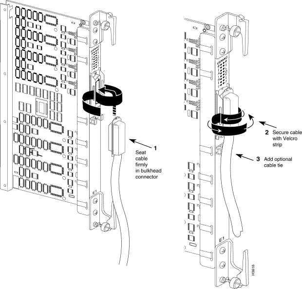
Table 3-2 shows the pin assignments common to the T1 and E1 CEMAC bulkhead connectors. The information in this table has been extracted from Figure 10 of American National Standard T1.403-1989. The T1/E1 CEMAC bulkhead connector is an RJ-48M connector.
| Port | Receive
| Transmit | ||
|---|---|---|---|---|
| Tip | Ring | Tip | Ring | |
0 | 26 | 1 | 39 | 14 |
1 | 27 | 2 | 40 | 15 |
2 | 28 | 3 | 41 | 16 |
3 | 29 | 4 | 42 | 17 |
4 | 30 | 5 | 43 | 18 |
5 | 31 | 6 | 44 | 19 |
6 | 32 | 7 | 45 | 20 |
7 | 33 | 8 | 46 | 21 |
8 - not used | 34 | 9 | 47 | 22 |
9 - not used | 35 | 10 | 48 | 23 |
10 - not used | 36 | 11 | 49 | 24 |
11 - not used | 37 | 12 | 50 | 25 |
When you use an E1 CEMAC in the 75-ohm mode, you must also use an E1 fantail and cable for interconnection with the bulkhead connector on the card. The fantail supports up to 12 ports. Figure 3-21 shows the E1 CEMAC fantail; Figure 3-22 shows the fantail cable.
To provide full compatibility with G.703 E1 interfaces, an E1 CEMAC fantail is available in either of two versions: one equipped exclusively with 12 BNC connectors, or one equipped exclusively with 12 SMZ connectors. For convenience, Figure 3-21 illustrates both types of connectors on the E1 CEMAC fantail.
When you interconnect the 8-port E1 CEMAC card to an E1 fantail using a fantail cable (see Figure 3-22), only the first eight transmit and receive ports (TX0 to TX7 and RX0 to RX7) on the fantail are used.
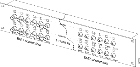
Refer to the LightStream 2020 Hardware Reference & Troubleshooting Guide for information about configuring the TX GND and RX GND jumpers on the E1 fantail.
A 50-pin cable is used to connect the bulkhead connector on the E1 CEMAC card and the back of the E1 fantail. This cable, illustrated in Figure 3-22, supports up to 12 ports.
The E1 fantail cable for a CEMAC card can be ordered from Cisco Systems in any of three lengths. Select the appropriate order number from the following table.
| Manufacturing No. | Length | Order No. |
72-1094-01 | 4 feet (1.2 m) | LS-CAB-8E1-4B= |
72-1095-01 | 8 feet (2.4 m) | LS-CAB-8E1-8B= |
72-1096-01 | 12 feet (3.6 m) | LS-CAB-8E1-12B= |
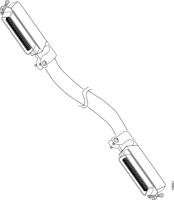
Figure 3-23 shows a bulkhead view of the following versions of the OC-3c access cards:
As shown in Figure 3-23, the bulkhead view of the second-generation, single-mode OC-3c card is identical to that of the multimode card, except that the former contains the nomenclature "OC3AC SM" at the top of its bulkhead.
The cables for the OC-3c access cards are described in separate sections below.
 | Caution Protective covers are provided for the connectors and cables associated with all the OC-3c access cards. Keep these covers in place on any OC-3c connectors or cables not in use to shield them from dust or damage, thereby minimizing the potential for optical signal attenuation or data loss. |

Multimode interface connector type: SC
Connectors per multimode access card: four (2 connectors per port; 2 ports, numbered 0 and 1)
Single-mode interface connector type: ST (SC connectors for second-generation, single-mode card)
Connectors per single-mode access card: four (2 connectors per port; 2 ports, numbered 0 and 1)
A single-mode OC-3c cable with simplex ST connectors is used to connect a first-generation, single mode OC-3c access card to a single-mode OC-3c interface. Cisco Systems does not provide this cable; it is readily available from other sources.
The single-mode OC-3c interface operates at a wavelength of 1300 nanometers.
Single-mode cables with ST connectors should conform to the following specifications:
Standard: EIA class IVa
Cabling: 8.3 micron core with a maximum attenuation at 1300 nanometers of .3 dB/km. Optical path loss should not exceed 12 dB.
Maximum path length (all cables in a connection from end to end): 22 km
Figure 3-24 shows the cable used with the first-generation, single-mode OC-3c access card. This cable is equipped with simplex ST connectors.

A single-mode OC-3c cable with SC connectors is used to connect a second-generation, single-mode OC-3c access card to a single-mode OC-3c interface. Cisco Systems does not provide this cable; it is readily available from other sources.
The single-mode OC-3c cable equipped with SC connectors is similar in appearance to the multimode OC-3c cable shown in Figure 3-26. However, the optical characteristics of the single-mode cable are different.
The single-mode OC-3c interface operates at a wavelength of 1300 nanometers.
The single-mode SC cables should conform to the following specifications:
Standard: EIA class IVa
Cabling: 8.3 micron core.
The path loss characteristics and maximum cable lengths for the single-mode OC-3c access card equipped with duplex SC connectors are discussed in the following section.
The Intermediate Reach (IR) transceiver used in the single-mode OC-3c access card equipped with duplex SC connectors has the power characteristics outlined in the table below.
| Transmit Power | Receive Power |
|---|---|
Minimum: -15 dBm Maximum: -8 dBm | Minimum: -31 dBm Maximum: -8 dBm |
1. The path loss (optical attenuation) characteristics of the fiber-optic cable selected for use with the access card
2. The number of segments (splices) in the overall (end-to-end) fiber-optic link
The supplier of the fiber-optic cable that you purchase for use with the single-mode OC-3c access card should be able to provide you with the path loss characteristics of the cable. With this information, you can use the maximum path loss value in the following table to determine whether the IR transceiver will meet your end-to-end optical transmission requirements.
| Transceiver Type | Maximum Path Loss |
|---|---|
Intermediate Reach (IR) | 16.0 dBm |
The maximum path loss value of 16.0 dBm is based on an assumed margin of 0 dB. This 16.0 dBm value is based on the transceiver's minimum optical input sensitivity and minimum optical output power. Hence, this value constitutes a "worst-case" path loss characteristic.
If you know the path loss characteristics of your selected fiber-optic cable and the number of splices contained in the end-to-end fiber-optic link, you can make a rough determination as to whether the single-mode IR transceiver will meet your optical transmission needs. Such a determination, however, must be based on the assumption that the optical attenuation characteristics of the cable are the same across all cable segments (or splices) in the entire end-to-end link.
In general, acceptable quality fiber-optic cable has a path loss characteristic of .3 dB/km or less. A path loss characteristic of .45 dB/km is considered quite poor.
If your overall fiber-optic link consists of link segments with different loss characteristics, you should regard each link as having the path loss characteristic of the worst link in determining aggregate attenuation losses.
Connector manufacturers specify the performance of a connector by measuring its "insertion loss." In calculating insertion loss, power flowing through a fiber-optic cable is measured. Next, the cable is cut in half and a connector is affixed. Power at the end of the cable is again measured. The difference in these two measurements are used to calculate the insertion loss.
This method eliminates losses caused by variations in cable diameters when cables from different vendors are spliced together. Typical insertion loss values range from .1 dB to .6 dB, depending on the quality and type of connector. In any case, you are advised to use a very conservative path loss value of 1 dB/km for fiber-optic links composed of multiple vendor or fiber types.
For the IR transceiver used in the single-mode OC-3c access card, consult either Table 3-3 or Table 3-4 to determine the maximum allowed cable lengths (in kilometers), given specific assumptions about the number of splices contained in the end-to-end link and the loss characteristics of each splice.
Table 3-3 shows the maximum cable lengths for end-to-end connections that incur a loss of .5 dB/splice.
| Fiber Loss (dB/km) | 2 Splices (1.0 dB loss) | 4 Splices (2.0 dB loss) | 6 Splices (3.0 dB loss) | 8 Splices (4.0 dB loss) |
|---|---|---|---|---|
.30 | 50.00 km | 46.67 km | 43.33 km | 40.00 km |
.35 | 42.86 km | 40.00 km | 37.14 km | 34.29 km |
.40 | 37.50 km | 35.00 km | 32.50 km | 30.00 km |
.45 | 33.33 km | 31.11 km | 28.89 km | 26.67 km |
Table 3-4 shows the maximum cable lengths for end-to-end connections that incur a loss of 1.0 dB/splice.
| Fiber Loss (dB/km) | 2 Splices (2.0 dB loss) | 4 Splices (4.0 dB loss) | 6 Splices (6.0 dB loss) | 8 Splices (8.0 dB loss) |
|---|---|---|---|---|
.30 | 46.67 km | 40.00 km | 33.33 km | 26.67 km |
.35 | 40.00 km | 34.29 km | 28.57 km | 22.86 km |
.40 | 35.00 km | 30.00 km | 25.00 km | 20.00 km |
.45 | 31.11 km | 26.67 km | 22.22 km | 17.78 km |
You can ascertain whether the single-mode OC-3c access card equipped with SC connectors will meet your optical transmission requirements by determining the overall path loss of your fiber-optic link and comparing this value against the following baseline:
If you cannot determine the overall path loss of your fiber-optic link, you must assume that the maximum transmit distance of the IR transceiver is no more than 50 km.
The transceivers on the second-generation, single-mode OC-3c access card are equipped with duplex SC connectors (see Figure 3-23). Note that you can attach either simplex or duplex SC optical cables to these bulkhead connectors.
Also, using an SC-to-ST optical cable adapter (see Figure 3-25), you can interconnect cables from a second-generation, single-mode access card with another OC-3c device equipped with ST connectors.
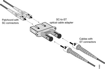
The following components are required for interconnecting the second-generation OC-3c access card equipped with SC connectors to another fiber optic device equipped with ST connectors:
Suggested patchcord vendors are listed in the following table.
| Vendor | Part Number | Quantity Required |
|---|---|---|
3M | ADADA-MK 0001 | Two (simplex) |
AMP | 503627-1 | One (duplex) |
This adapter is available from the vendor indicated in the following table.
| Vendor | Part Number | Quantity Required |
|---|---|---|
AMP | 503137-5 | One (duplex) |
This cable is used to connect a multimode OC-3c access card to another multimode OC-3c interface.
Cisco Systems does not provide this cable; it is widely available from other sources.
The OC-3c interface operates at a wavelength of 1300 nanometers.
A multimode OC-3c cable with SC connectors should conform to the following specifications:
Standard: ISO/IEC 9314-3
Cabling: 62.5 micron core with an optical loss of 0 to 9 dB, or 50 micron core with an optical loss of 7 dB. You should not mix 62.5 and 50 micron cables in the same fiber-optic link.
Maximum path length (all cables in a connection from end to end): 2 km
Figure 3-26 shows an OC-3c multimode cable equipped with simplex SC connectors.

Figure 3-27 shows the bulkhead view of an FDDI access card (FAC).
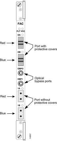
Interface connector type: media interface connector (MIC); two MIC connectors per port, one for transmit and one for receive
Connectors per access card: four, one labeled A (red) and one labeled B (blue) for each of two ports. The MIC connectors are keyed to ensure proper cable connections to the access card.
This cable is used to connect a multimode FDDI access card to another FDDI device. Cisco Systems does not provide this cable; it is widely available from other sources.
The FDDI interface operates at a wavelength of 1300 nanometers.
FDDI cables should conform to the following specifications:
Cabling: 62.5 micron core, graded-index fiber with an optical loss of 11 dB and a maximum cable attenuation of 1.5 dB/km at 1300 nanometers.
Maximum path length (all cables in a connection from end to end): 2 km
 | Caution Protective covers are provided for all FDDI access card connectors and cables. Keep these covers in place on any FDDI connectors or cables not in use to shield them from dust or damage, thereby minimizing the potential for optical signal attenuation or data loss. |
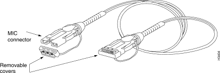
Figure 3-28 shows a physical representation of the FDDI cable.
This section describes the bulkhead connectors and cables for the Ethernet access card (EAC).
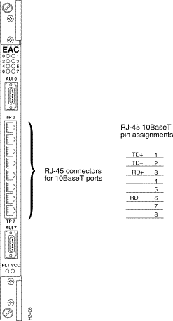
Figure 3-29 shows the bulkhead view of the Ethernet access card, which includes eight RJ-45 connectors and two attachment unit interface (AUI) DB-15 connectors. The RJ-45 connectors are used for the twisted pair Ethernet (10BaseT) ports.
 Connector Pin Assignments
Figure 3-29 shows the RJ-45 connectors and their pin assignments on the Ethernet access card. These connectors are used for Ethernet twisted pair (10BaseT) ports.
The cables used with the RJ-45 ports on the Ethernet access cards are described in the following sections.
This cable is used for the following purposes:
Cisco Systems does not provide this cable; it is widely available from other sources.
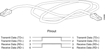
Figure 3-30 shows a physical representation of the Ethernet 10BaseT (twisted pair) straight-through cable and provides a schematic diagram of its pin assignments.
This cable is used to directly connect an Ethernet access card to another device on the Ethernet, such as a workstation.
Cisco Systems does not provide this cable; it is widely available from other sources.
Figure 3-31 shows a physical representation of the Ethernet 10BaseT (twisted pair) crossover cable and provides a schematic diagram of its pin assignments.
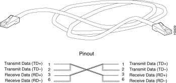
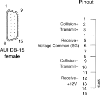
Figure 3-32 shows the pin assignments for the two 15-pin Ethernet AUI connectors on the Ethernet access card (EAC) and the same connector on the network processor (NPAC) card. The top AUI connector on the EAC is for port 0, and the bottom connector is for port 7.
The AUI DB-15 connector pin assignments shown in Figure 3-32 apply to the following access cards:
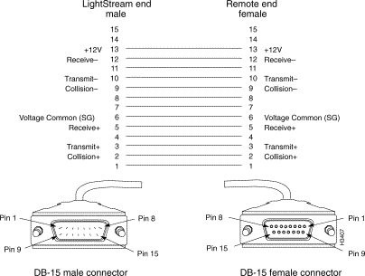
This cable connects an AUI port on the Ethernet access card to an Ethernet 10Base2, 10Base5, or 10BaseFL transceiver. This cable also works with the Ethernet (E-NET) port on the network processor access card (NPAC).
Cisco Systems does not provide this cable; it is widely available from other sources.
Figure 3-33 shows a schematic diagram of the Ethernet access card AUI cable.
This section describes the fiber Ethernet access card (FEAC) connectors and associated data cable.
Figure 3-34 shows the bulkhead view of the fiber Ethernet access card (FEAC).

This cable is used to connect a multimode fiber (10Base-FL) Ethernet access card to another fiber Ethernet device.
Cisco Systems does not provide this cable; it is widely available from other sources.
The fiber Ethernet interface operates at a wavelength of 850 nanometers.
Multimode fiber Ethernet cables should conform to the following specifications:
Standard: ISO/IEC 9314-3
Maximum path length (all cables in a connection from end to end): 2 km
Cabling: 62.5 micron core with an optical loss of 0 to 9 dB, or 50 micron core with an optical loss of 7 dB. You should not mix 62.5 and 50 micron cables in a single fiber optic link.
 | Caution Protective covers are provided for all fiber Ethernet access card connectors and cables. Keep these covers in place on any fiber Ethernet connectors or cables not in use to shield them from dust or damage, thereby minimizing the potential for optical signal attenuation or data loss. |
Figure 3-35 illustrates the multimode fiber Ethernet cable equipped with ST connectors.

Figure 3-36 shows the bulkhead view of the console/modem assembly. This assembly is installed in the rear of the LS2020 chassis.

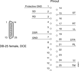
Figure 3-37 shows the pin assignments of the RS-232 modem port (DB-25 connector). This port is labeled "MODEM" on the bulkhead of the console/modem assembly (see Figure 3-36).
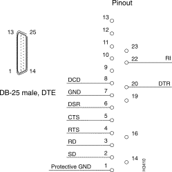
Figure 3-38 shows the pin assignments of the RS-232 console port (DB-25 connector). This port is labelled "CNSL" on the bulkhead of the console/modem assembly located (see Figure 3-36).
This cable is used to connect the console or modem port on the LS2020 console/modem assembly to an external console or modem.
Cisco Systems does not provide this cable; it is widely available from other sources.
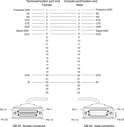
Figure 3-39 shows the DB-25 connectors associated with the RS-232 straight-through data cable and provides a schematic diagram of the pin assignments for the cable.
The Release 2 switch card incorporates a building-integrated timing source (BITS) interface for constant bit rate (CBR) applications. The BITS interface is a receive-only T1 line that extracts only the clock signal from a T1 line (data is discarded). The clock signal is used to support the Nettime network timing feature.
The clock signals provide a highly stable time reference for use in an LS2020 chassis or within the network. Figure 3-40 shows the bulkhead view of the Release 2 switch card and defines the pin assignments of the RJ-48C connector for the BITS CLK port.

If you are specifying a cordset as part of a new system order, refer to the LS2020 price list or the Cisco Systems Product Catalog and order the appropriate country power kit. Doing so ensures that you will also receive the appropriate labels and instructions for the country of destination.
If you want to check the cordset included in a specific country power kit, refer to Table 3-5, which cross-references cordset product numbers and country power kit models.
If you need to order a replacement cordset that is not part of a country power kit, you must reference the cordset's part number. This part number (P/N) appears above each cordset illustrated in the section below entitled "LightStream 2020 AC Power Cordsets."
A DC-powered system does not use a detachable power cord. Instead, a 48 VDC power source must be permanently wired to a DC power tray in the LS2020 chassis. This work should be done only by a licensed electrician or otherwise qualified individual.
For instructions on wiring a DC-powered system, see the LightStream 2020 Installation Guide.
Each LS2020 AC power tray is equipped with one recessed male power inlet. The power connectors conform to IEC Standard 320 C20 and require cordsets with an IEC 320 C19 female connector. (All cordsets offered by Cisco Systems for the LS2020 switch have IEC 320 C19 female connectors.)
Each AC country power kit consists of a plastic bag containing a country-specific AC power cordset and sufficient attachment hardware (screws, nutclips, and washers) for use in attaching hardware to any of the 12 slots in the mounting flanges of the LS2020 rack.
Table 3-5 summarizes the specifications of the AC power cordsets. The table lists the country of use, the cordset rating, its plug type, its manufacturing part number, and the country power kit order number for each cordset.
Following Table 3-5 is a series of illustrations summarizing the specifications of all the power cordsets available for the LS2020 switch. These summaries are arranged according to the cordset manufacturing part number.
| Country of Use | Cordset Rating | Plug Type | Mfg. Part Number | Country Power Kit Order Number |
Canada, Mexico, Japan, and USA | 125V @ 20A | NEMA 5-20P | 37-0037-01 | L2020-PWR-NA= |
Canada, Mexico, Japan, and USA | 125V @ 20A | NEMA L5-20P | 37-0038-01 | L2020-PWR-NA125= |
Canada, Mexico, Japan, and USA | 250V @ 20A | NEMA L6-20P | 37-0039-01 | L2020-PWR-NA250= |
Continental Europe, including Austria, Belgium, Finland, France, Germany, Holland, Norway, Portugal, Spain, and Sweden | 250V @ 16A | CEE 7/7 | 37-0040-01 | L2020-PWR-E= |
Argentina, Australia, New Zealand, and Papua New Guinea | 250V @ 15A | AS3112-1981 | 37-0041-01 | L2020-PWR-A= |
Denmark | 250V @ 10A | 107-2-DI | 37-0042-01 | L2020-PWR-D= |
England, Hong Kong, Ireland, Malaysia, Scotland, Singapore, and Wales | 250V @ 13A | BS 1363 | 37-0043-01 | L2020-PWR-U= |
India and South Africa | 250V @ 15A | BS 546 | 37-0044-01 | L2020-PWR-IN= |
Israel | 250V @ 16A | SI 32 | 37-0045-01 | L2020-PWR-IS= |
Italy | 250V @ 16A | CEI 23-16 | 37-0046-01 | L2020-PWR-I= |
Switzerland | 250V @ 10A | SEV 1011 | 37-0047-01 | L2020-PWR-CH= |
![]()
![]()
![]()
![]()
![]()
![]()
![]()
![]()
Posted: Wed Oct 2 06:04:30 PDT 2002
All contents are Copyright © 1992--2002 Cisco Systems, Inc. All rights reserved.
Important Notices and Privacy Statement.