|
|

The hardware elements of a LightStream 2020 multiservice ATM switch (LS2020 switch) are outlined in Table 1-1. This chapter describes each component of an LS2020 node, starting with the chassis and midplane. For a detailed description of line cards, access cards, and fantails refer to the chapter entitled "Interface Modules."
Table 1-1 LS2020 Hardware Components
| Hardware | Description |
|---|---|
Network Processor Card (NP card) |
|
Interface Modules (line and access cards) |
The LS2020 switch is a Class A device, as defined by FCC rules. For information about certifications, compliances, and standards met by the LightStream 2020, refer to the LightStream 2020 Site Planning and Cabling Guide.
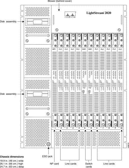
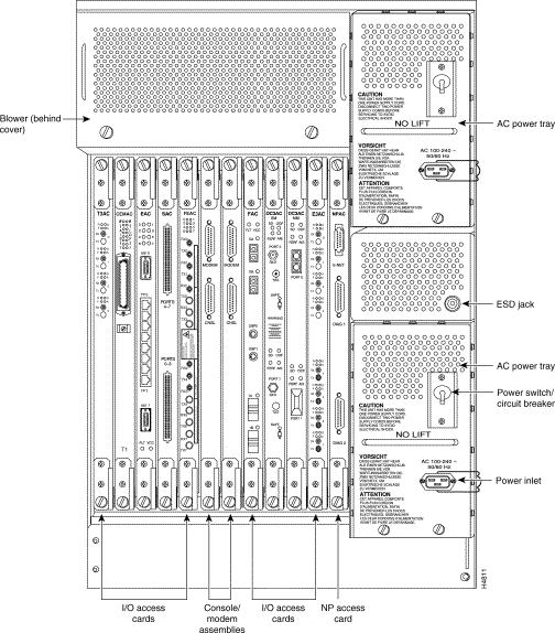
The chassis serves as a skeleton and container for the LS2020 system. It provides access to components from both the front and back. It contains all the hardware elements listed in Table 1-1. Figure 1-1 and Figure 1-2 show front and rear views of the chassis.
From the front of the LS2020 chassis, you have access to network processor cards, line cards, switch cards, disk drive units, and one of the two blowers. Power supplies, access cards, external cabling, connectors for consoles and modems, and the other blower are accessible from the rear of the chassis.
The 12 slots in the chassis are divided into function card slots, numbered 1 through 10, and switch card slots, designated A and B.
The LS2020 chassis can be mounted in a standard 19 inch wide rack. Guidelines for selecting racks are provided in the LightStream 2020 Site Planning and Cabling Guide; rack mounting instructions appear in the LightStream 2020 Installation Guide.
Each LS2020 node has a midplane that contains most of the internal wiring for the node. The midplane is a field-replaceable unit (FRU) that
The midplane is designed to simplify system assembly, increase reliability, and improve mean time to repair. Figure 1-3 shows a top-down conceptual view of a midplane with several cards connected.
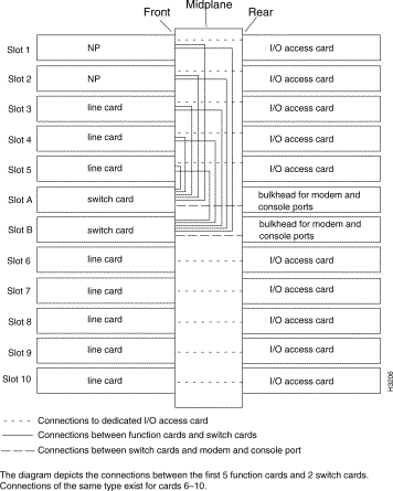
NPs, line cards, and switch cards plug into the front of the midplane, and I/O access cards associated with each function card plug into the rear of the midplane. Function cards and their I/O access cards are connected by connector pins that pass through the midplane (without making an electrical connection with the midplane). The midplane contains all the internal wiring to connect the function cards to the switch cards.
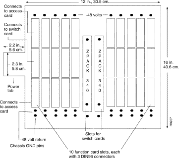
Up to ten function cards and two switch cards can be connected to the front of the LS2020 midplane. Figure 1-4 shows the connectors on the front of the midplane.
In a fully redundant system, the following items are connected to the midplane:
At a minimum, a system must have at least one of each item. On a system with only one NP card, the extra slot can be used for an additional interface module.
The function cards connect to the switch card by way of the center 96-pin DIN connector in each slot. The upper and lower 96-pin DIN connectors are used to connect the function card to the access card on the other side of the midplane.
| Caution Function card and switch card midplane connectors are different. Do not attempt to place a function card in a switch card slot or vice versa. Attempts to do so may result in damage to the connectors on the midplane or the cards. |
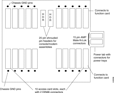
Up to ten I/O access cards, two console/modem assemblies, and two power supplies can be connected to the back of the midplane. Figure 1-5 shows the connectors on the back of the midplane.
The 96-pin DIN connectors in each slot connect the access card to the function card on the other side of the midplane.
Each bulk power tray connects to one connector on the rear of the midplane. The console and modem ports for each switch card share one shrouded-pin header connector located on the rear of the midplane behind the switch card.
On the midplane are two EEPROM chips whose contents, which are written in the factory, include
(A modem port is associated with each switch card.)
If you replace the midplane, you may need to program some of the information listed above into the EEPROMs on the new midplane. Refer to the midplane replacement procedure in the chapter entitled "Replacing FRUs."
The chassis IDs in the two midplane EEPROMs in an LS2020 switch must be identical, and they must be otherwise unique in your network. For this reason, Cisco assigns a unique chassis ID number to every LS2020 switch. To ensure that the correct chassis ID is restored in the event of an EEPROM failure, you should keep a record of the chassis ID for every system in your network.
| Caution You may wish to change the modem initialization string and modem password on your system. If you change these values for one switch card slot, be sure to change the values for the other slot to match. If modem information is not consistent across slots, you could have modem access problems if you move a switch card from one slot to another or if, in a redundant configuration, your backup switch card becomes active. |
The LS2020 chassis takes in cooling air from the front. Air is drawn up through the chassis and is exhausted at the back and the right side by blower units like the one shown in Figure 1-6.
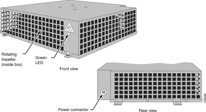
There are two blowers located at the top of the chassis in each LS2020 system. One blower is accessible from the front and the other from the rear. Each blower is an FRU. During normal operation, both blowers should be running. If one blower fails, the system can continue to operate; however, the failed blower should be replaced as soon as possible.
Each blower has a green LED that illuminates to indicate that the impeller is spinning at a rate of at least 1500 rotations per minute. On the rear blower, the LED is visible through the blower cover. You must remove the blower cover to see the LED on the front blower.
The blowers have two speeds and normally run at low speed. The blower speed is temperature controlled: the speed automatically varies as needed to maintain the temperature. The blowers run at the lower speed whenever possible, which provides the quietest operation.
The blowers run at high speed for 90 seconds after the system is first powered on, and then slow down. The decrease in speed is audible to anyone standing near the chassis.
In addition to the main air flow through the chassis, each bulk power tray in an AC-powered system contains its own fans.
The cooling system operates properly only when all cards, bulkheads, filler panels, covers, and components are in place. Removing these items disrupts the flow of air through the chassis. As a result, components may be shut down due to overheating.
In an LS2020 switch, a bulk power tray unit converts power from an external source to bulk DC voltage before distributing DC power to the individual function and switch cards. The nominal voltage of the bulk power unit is 48 volts.
LS2020 systems are available with two power options:
There are up to two power trays in each chassis; each power tray is an FRU. If there are two power trays, both are connected to a 48-volt rail so that either tray can drive the entire system.
The power tray slots, designated A (on top) and B (on the bottom), are accessible from the rear of the chassis. See Figure 1-2.
Each card in an LS2020 switch converts bulk power to its point-of-use voltages. The power converters on each card are controlled separately by the associated on-card TCS slaves. Each TCS slave can turn its converter on and off and voltage-margin the converter. This arrangement allows for a nondisruptive hot-swap capability and aids in fault diagnosis.
The TCS is powered independently from the rest of the system so that it can control power and run margining tests without impairing its own operation. TCS power is distributed from the switch card to all other cards in the chassis.
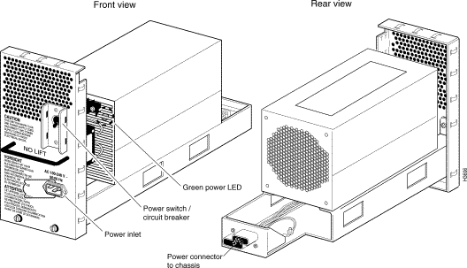
AC power supplies accept input power over a continuous range from 100VAC to 240VAC at 50 Hz or 60 Hz. No adjustment or configuration is required. An AC power supply is shown in Figure 1-7.
Each AC power tray has one recessed male power inlet that conforms to IEC standard 320 C20; it requires a power cord with an IEC 320 C19 connector. See the LightStream 2020 Site Planning and Cabling Guide for more information on power cords.
If a system has two power trays, the trays must be plugged into separate electrical circuits for true redundancy.
Each AC power tray has a circuit breaker that turns that power tray on and off; it can be tripped by an electrical event or operated manually.
Each AC power tray has a green LED that comes on when the system is powered up.
| Caution The handle on the AC power tray is designed to support the weight of the tray only. Do not use the power tray handle to lift the chassis. |
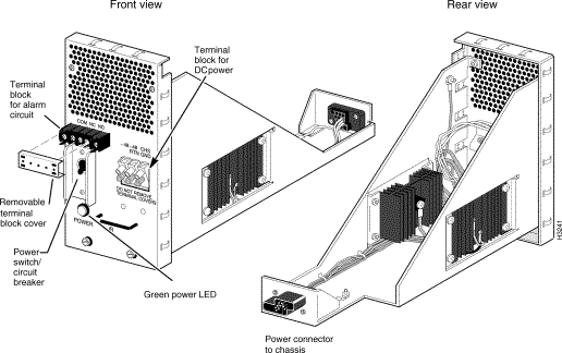
DC-powered LS2020 systems accept power over a continuous range from -43VDC to -60VDC. No adjustment or configuration is required. Power from an external -48VDC source is brought into the system by the DC power tray. A DC power tray is shown in Figure 1-8.
The green LED on each DC power tray illuminates to indicate the presence of DC power. The LED, which is mounted on the power tray and is visible from the rear of the chassis, is connected after the circuit breaker and before the isolation diodes. This allows the LED to indicate the presence or absence of power individually for each tray, prior to the or-ing of the power feeds.
DC-powered LS2020 systems do not use detachable power cords; they must be permanently wired to a DC power source by qualified service personnel. Systems with the optional second power tray can be wired from a dual power feed. (For more information on wiring DC-powered systems, refer to the LightStream 2020 Installation Guide.)
Each DC power tray has a circuit breaker that turns system power on and off; it can be tripped by an electrical event or operated manually.
| Warning To turn off power in a DC system with two power trays, you must set the circuit breakers on both trays to off. If only one is turned off, the system remains fully powered. |
The DC power tray is equipped with an optional circuit breaker alarm that can be connected to an external device such as a light panel.When the circuit breaker is tripped, the alarm is triggered, notifying you that the system is no longer receiving power through that power tray. The COM (common), NO (normally open), and NC (normally closed) contacts on the DC power tray provide the alarm signal by indicating whether the circuit breaker is open (off/tripped) or closed (on).
Table 1-2 summarizes the possible positions of the contacts.
Table 1-2 Circuit Breaker Alarm Conditions
The alarm contacts have a maximum rating of 10A at 250VAC (60 Hz) or 3A at 50VDC.
The LS2020 switch card, an FRU, provides the interconnection through which line cards and network processors (NPs) in the same chassis communicate with one another. Communications between NPs and line cards can take place over high-speed switch paths that carry payload traffic between LS2020 nodes. In addition, low-speed Test and Control System (TCS) data paths carry control and diagnostic information between the TCS hub on the switch card and the TCS slaves on the NP and line cards.
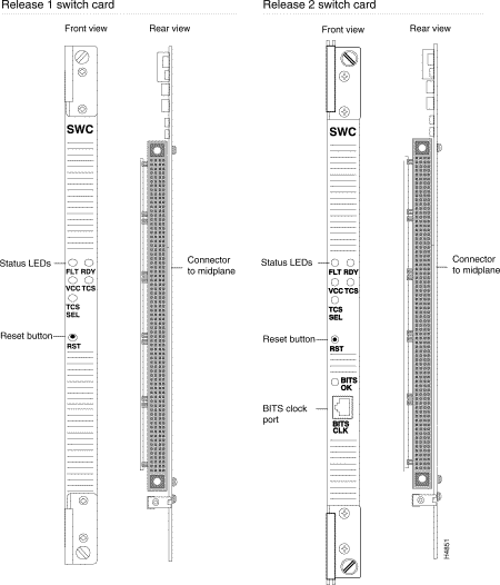
Two versions of the switch card exist: Release 1 and Release 2. Except as noted, functionality is identical on the two cards.
Switch cards are inserted in one or both of the dedicated switch card slots on the front of the midplane, slots A and B. A redundant system has two switch cards; a nonredundant system has one. In a redundant system, one switch card is active and the other serves as a hot spare, ready to take over if the active card fails.
There is a recessed reset pushbutton on the card's front bulkhead. Pushing it causes a full reset of the card. The LEDs on the switch card are described in the Appendix "LEDs."
Figure 1-9 shows the front view and rear view of Release 1 and Release 2 switch cards.
The switch card has four key functional areas:
Figure 1-10 shows a high-level functional block diagram of the switch card. Each of the functional areas shown in Figure 1-10 is described in the sections that follow.
The concurrent cell switch provides the connection through which NPs and line cards communicate, allowing them to transport cells of data between function cards within an LS2020 chassis. As shown in Figure 1-10, the concurrent cell switch has 10 ports, one per function card slot.
The concurrent cell switch on each switch card takes the place of a bus in a conventional computer system. It eliminates the need for high-power drivers for high-speed, high-fanout buses. It provides physical isolation between function card data paths for power-on, nondisruptive servicing. It also provides a very high aggregate bandwidth in the chassis without requiring each function card to accept data at the aggregate rate.
The switch carries cells in fixed length time slots, which are common to all the traffic. All function cards transmit their cells into the switch simultaneously and receive cells from the switch simultaneously.
In the time slot preceding the data transfer, the switch selects the transmitting function card that will get a connection with its requested receiving function card. Then, it sends an acknowledgment back to those transmitters whose transmission requests will be fulfilled. The transmitter begins the data flow as the next time slot begins.
The function cards are connected to the switch by private links. There are three paths between each function card and the switch. One is used to transmit cells from the function card to the switch, and two are used to deliver cells from the switch to the function card. Each of these data paths is eight bits wide and is clocked at 25 MHz, for a raw path bandwidth of 200 Mbps.
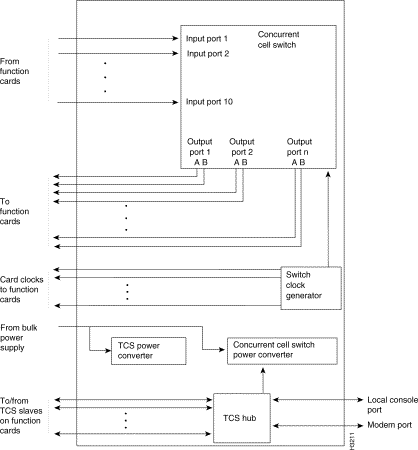
The data passing on these links is divided into cells. Each link is unidirectional, but the three data paths between the function card and the switch can all pass cells simultaneously. The double data paths flowing from the switch to the function cards reduce blocking probability so the switch delivers better performance than ordinary "nonblocking" switches. Under typical traffic loads, the concurrent cell switch delivers an average of 160 Mbps of cell payload throughput. This is more than enough to handle the 149.8 Mbps OC-3c SONET payload bandwidth, and sufficient to handle wire-speed FDDI traffic with enough margin to accommodate inefficiencies due to packet fragmentation.
Switch cards include a single-chip microcomputer that supports certain specialized functions, such as initialization routines and diagnostics. The microcomputer, which runs the integrated test and control system (TCS) is described in detail in the appendix "TCS Hub Commands."
The TCS hub is located on the switch card. (See Figure 1-10.) It controls the switch card and acts as a communications hub for the system-wide test and control system. It provides communication among the TCS slaves, the console, the TCS hub on the redundant switch card if one is present, and the modem. The TCS hub can monitor the "DC OK" signal on the bulk power supply.
The switch card provides power for the entire TCS system.
In a system with two switch cards, the TCS hub on one card is primary and the TCS hub on the other is secondary. The active switch card—that is, the switch card whose switching fabric is currently in use—is not necessarily the same card on which the primary TCS hub is located. Use any of the following methods to identify the switch card with the primary TCS hub:
For example, TCS HUB <<B>> indicates that the primary hub is on the card in switch slot B: and tcs hub <<a>> indicates that the secondary hub is on the switch card in slot A.
By way of the local console and modem ports, both TCS hubs can provide some access to function cards. For example, you can display the status of a function card from either hub. However, if you need to establish a console connection to a card—for example, to use the command line interface (CLI) or to run diagnostics—you must connect to the card via the console or modem port of the switch card with the primary TCS hub.
If the primary hub fails to poll the secondary hub within a specified time period, the secondary hub takes over and becomes primary. In addition, you can force the secondary hub to become primary, as described in the LightStream 2020 Network Operations Guide. Forcing the hubs to switch roles may be necessary, for example, if you need to remove a switch card from the chassis.
On the Release 1 switch card, there are two power supplies. One supplies TCS power for the entire LS2020 switch, and the other supplies power to the concurrent cell switch and clock circuitry. On the Release 2 switch card, a single power supply serves both purposes.
The switch card converts internally distributed bulk power to the voltages it needs to operate its switch circuitry and generates power for the TCS system on all the function cards.
A switch card generates a 25-MHz clock signal for the system and distributes it to all the function cards. (See Figure 1-10.)
The Release 2 switch card incorporates network synchronization logic. The BITS CLK port and the BITS OK LED are useful for constant bit rate applications. BITS (building-integrated time source) refers to a type of T1 line that carries a valid T1 signal, and may be used to provide a highly stable time reference for the LS2020 switch.
With appropriately configured hardware, software, and network management tools, an LS2020 switch can globally synchronize constant bit rate (CBR) interfaces in an LS2020 network to a single reference clock signal. This network timing distribution service, called Nettime, enables synchronous clocking and synchronous residual time stamp (SRTS) clocking functions to be accomplished through an LS2020 switch. This reference clock signal can be distributed throughout all trunks in an LS2020 network except for the low-speed access cards, the medium-speed access cards, and the serial access cards. For more information on Nettime, see the LightStream 2020 System Overview.
An LS2020 node's optional second switch card is used for redundancy rather than loadsharing. The two cards are configured identically.The switch card whose switching fabric is currently in use is called the active switch card. The other is the backup. When an active switch card goes out of service, the system automatically cuts over to the backup.
Cutovers are handled differently by Release 1 and Release 2 switch cards.
In a redundant system, the active switch card is in slot A unless that card is absent, off, has failed, or the operator has forced a cutover. You can identify the active switch card by issuing the show chassis primaryswitch at the CLI prompt.
The active switch card is not necessarily the card on which the primary TCS hub is located. (See the section "TCS Hub," above, for details.)
At the back of the chassis, behind each switch card, is a console/modem assembly consisting of a bulkhead with two connectors mounted on it. (See Figure 1-11.)

The connectors are labeled CNSL and MODEM. The console/modem assembly connects to the midplane via a ribbon cable. Its ports can be used to connect a terminal and modem to the TCS hub on the switch card; from there you can connect to the NP or to any other function card.
The NP card, an FRU, is the LS2020 system's primary computing and storage resource.
In conjunction with the line cards, network management systems, and NPs in other LS2020 nodes, the NP performs system-level functions for the LS2020 node. These functions include virtual circuit management, network management, maintenance of routing databases, distribution of routing information, and file system management.
Each NP is paired with an NP access card, which resides directly behind the NP in the chassis. The access card provides an Ethernet port that may be connected to carry network management traffic. Signals are carried from the NP to both the switch card and the NP access card by 96-pin DIN connectors on the midplane.
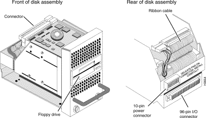
The NP card is connected to a disk assembly—a 3.5-inch floppy disk drive and a hard disk drive with at least 120 Mbytes of storage. The NP and the disk assembly are connected by a ribbon cable. See the section "Disk Assembly " for more information on the disk assembly.
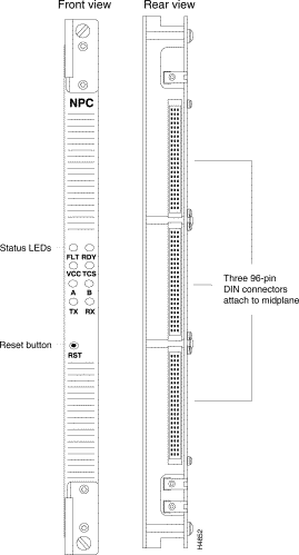
There is a recessed reset pushbutton on the card's front bulk-head. Pressing it causes a full reset of the card.
Note The reset button does not bring the NP down gracefully. You should reboot the NP to bring it down gracefully, as described in the "Performing an Orderly Shutdown" section of the "Replacing FRUs" chapter.
In addition, the NP card includes a single-chip microcomputer that supports certain specialized functions, such as initialization routines and diagnostics. The microcomputer, which runs the integrated test and control system (TCS) is described in the appendix entitled "TCS Hub Commands."
The LEDs on the NP are described in the appendix entitled "LEDs." Figure 1-12 shows front and rear views of the NP card.
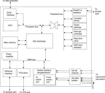
The network processor (NP) facilitates system operations. Its functions include call processing and rerouting, LAN bridging and address translation, CLI monitor and control functions, discovery of network topology, and maintenance of network statistics.
The NP is a single-card microcomputer with an interface to the concurrent cell switch. Each NP uses a Motorola 68040 CPU and has 32 megabytes (MB) of DRAM. In addition, the NP has an Ethernet interface to carry network management traffic to and from a network management station or other LS2020 nodes, and a SCSI interface for the NP's local hard disk and floppy drive. The NP also has a battery-backed clock/calendar, several counter/timers for performance measurements and event logging, and a TCS slave. Figure 1-13 is a functional block diagram of an NP. The components in Figure 1-13 are described below.
Note In Release 1, NPs had 16 MB of memory. 16-MB NPs are not capable of running software releases numbered 2.0 or higher. If you have Release 1 NPs in your network, you must upgrade them before upgrading your software.
A node's optional second NP serves as a backup. The two NPs are configured exactly alike. One NP operates as primary while the other is available as a hot spare. When a failure is detected in the primary NP or in its associated disk assembly, switchover to the backup card happens automatically.
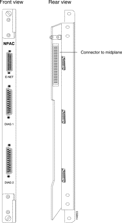
The NP access card supports one Ethernet port and a pair of serial ports. The Ethernet port can be used to connect the NP to an Ethernet for purposes of managing the LS2020 system. The two serial ports are used for module testing and debugging.
Figure 1-14 shows front and rear views of the NP access card.
Associated with each NP in an LS2020 chassis is a disk assembly (see Figure 1-15). The disk assembly is an FRU; it includes a 120-MB or larger hard disk drive, a 3.5-inch floppy disk drive, and a power supply.
The hard disk stores the node's system and application software, hardware diagnostics, and local configuration files.
The lower disk assembly is connected to the NP in slot 1; the upper disk assembly, if present, is connected to the NP in slot 2.
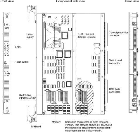
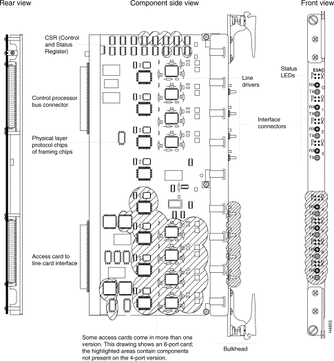
An interface module consists of a line card used in conjunction with an I/O access card. The line card provides higher layer data transfer functions. The access card provides the active logic for the physical layer interface for each port (line drivers/receivers, and so forth). In addition, certain interface modules support more ports than can be accommodated on the access cards. The necessary connectors are provided by fantail devices.
Interface modules allow LS2020 systems to connect to other networks and systems, including local area networks (LANs), wide area networks (WANs), metropolitan area networks (MANs), directly connected hosts, and other LS2020 systems. This section provides a overview of the interface modules. For detailed information, see the chapter entitled "Interface Modules."
Interface modules can be divided into two categories: trunk modules and edge modules. Trunk modules connect two LS2020 nodes and carry only cells.
Edge modules connect to devices outside of the LS2020 network and handle packet traffic, as well as ATM UNI cells, from another network or host to a LS2020 network.
Table 1-3 provides a descriptive summary of interface modules available for the LS2020.
Table 1-3 Interface Module Summary
Figure 1-16 shows a line card and identifies some of the elements common to all line cards, while Figure 1-17 does the same for access cards.
![]()
![]()
![]()
![]()
![]()
![]()
![]()
![]()
Posted: Wed Jan 22 23:47:18 PST 2003
All contents are Copyright © 1992--2002 Cisco Systems, Inc. All rights reserved.
Important Notices and Privacy Statement.