|
|

This chapter provides detailed descriptions of each line card, access card, and fantail supported by an LS2020 switch. For an overview, refer to the chapter entitled "Hardware Overview."
Interface modules consist of line cards, access cards, and, sometimes, cabling and fantails. In combination, these elements allow a LightStream 2020 multiservice ATM switch (LS2020 switch) to connect with other systems and networks. Table 2-1 lists each function card and its available access cards.
Table 2-1 Function Cards and Associated Access Cards
| Function Card | Access Card |
|---|---|
|
E3 Access Card (E3AC) T3 Access Card (T3AC) |
|
AUI/10Base-T Ethernet Access Card (EAC) Fiber Ethernet Access Card (FEAC) FDDI Access Card (FAC) AUI/10Base-T Ethernet Access Card (EAC) T1 and E1 Circuit Emulation Access Cards (T1 CEMAC and E1 CEMAC) Serial Access Card (SAC) |
|
Low-Speed Access Card (LSAC) |
|
E3 Medium-Speed Access Card (E3 MSAC) T3 Medium-Speed Access Card (T3 MSAC) |
For information about the network processor card and switch card, see the chapter "Hardware Overview."
A line card reformats each incoming unit of data as needed, makes the necessary low-level routing and congestion avoidance decisions, and directs the data to its destination. For each outgoing unit of data, a line card checks for errors, queues the data for transmission through the appropriate interface port, supplies the buffering needed to match the rate between the concurrent cell switch and the interface port, and handles congestion events. All line cards segment incoming data into cells; edge cards reassemble the cells into the format required by the external interface.
Since line cards must be capable of handling high data rates and the processing requirements are relatively simple, all routine packet and cell forwarding operations are handled by hardware and firmware. Each line card also includes a line card control processor that handles the more complex tasks that must be executed in a tens of milliseconds or less. The line card control processor acts as an agent for the NP when an NP needs to query or change the state of a line card. To gather statistics from a line card, for example, an NP sends a message to the line card control processor, and the line card control processor reads the appropriate hardware registers and returns a result to the NP.
Cell edge cards accept ATM cells from up to two OC-3c lines or up to eight T3 or E3 lines, update the cell headers, and forward them to the switch. They send cells received from the switch out of the network.
Packet and low-speed edge cards accept packets from up to eight lines, chop them into cells, and inject the resulting stream of cells into the switch. In addition, they receive cells from the switch, repackage the data as packets, and send them out of the network. Edge LSCs and edge PLCs also enforce the LS2020's backward congestion control scheme by discarding traffic on channels that send faster than their committed and excess rates allow. The cards smooth all datagram traffic that is injected into the switch. Isochronous traffic is injected into the switch on a fixed schedule to avoid statistical effects that result in unpredictable delays.
Medium-speed edge cards accept ATM cells from up to two T3 or E3 lines, update the cell headers, and forward them to the switch. They send cells received from the switch out of the network. MS cards do not enforce traffic shaping.
Trunk cards of all types accept LS2020 cells from trunk lines and replace their headers with new values for the next hop. The cells are then injected into the switch. Trunk cards also receive cells from the switch and send them on to the lines with no ATM header field replacement.
An LS2020 line card has two major logical portions: a line-specific portion and a generic portion. See Figure 2-1. The line-specific portion attaches to the external media or system and performs the functions required by that system.
The generic portions of line-card logic perform functions that occur regardless of the line type. These are the functions that allow packets or cells to be transferred through the LS2020 network. These functions are summarized below.
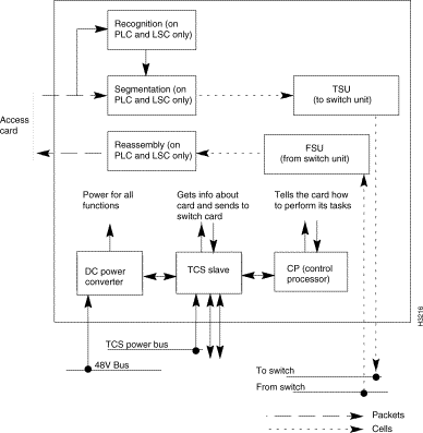
There are the following exceptions to these functions:
Each line card also has a TCS slave, which provides initialization and bootstrap for the line card. It performs local monitoring and power control functions required to support the mission critical features of the LS2020 node. The TCS slave communicates with the TCS hub through the midplane. For more information, see the appendix entitled "TCS Hub Commands."
Each line card is connected to an access card. Access cards, which are FRUs, provide the physical interface to which other devices can be connected. They are accessible from the rear of the chassis. Each access card connects to its function card through the midplane. If you remove or power down an access card, service is disrupted on the associated function card.
Certain interface modules support more ports than can be accommodated on the access cards. The necessary connectors are provided by fantail devices, shown in Figure 2-5, Figure 2-13, and Figure 2-15. Fantails, which are FRUs, provide connectors for four to 12 ports each. Up to two fantails per interface module may be required.
The cell line card (CLC) supports over 357K cells per second aggregate bandwidth and can handle bursts up to 893K cells per second. The CLC is designed to support up to 15 ports. The card is shown in Figure 2-2. The CLC supports the access cards shown in Table 2-2.

The CLC supports both trunk and edge interfaces. With the OC-3c access cards, it supports one trunk port or up to two edge ports. With the E3 and T3 access cards, it supports up to four trunk ports or up to eight edge ports.
The CLC is available with one or two TSUs (To Switch Units). The table shows those access cards supported by the both the 1- and 2-TSU CLCs and those supported by only the 2-TSU CLC.
Table 2-2 Access Cards Supported by CLCs
| Access Card | 1-TSU CLC | 2-TSU CLC |
The CLC's control processor is a 25-MHz Motorola 68EC030 microprocessor. Associated with the control processor are 4 MB of DRAM and 1 MB of Flash EPROM that stores bootstrap and POST code.
The LEDs on this card are described in the appendix "LEDs."
OC-3c access cards operate in conjunction with cell line cards. Four versions of the OC-3c access card are available, with the options shown in Table 2-3. The cards are labelled OC3AC MM (for multimode) or OC3AC SM (for single mode). All versions of the card operate at a wavelength of 1300 nanometers.
Note The 2-port OC3AC requires the 2-TSU cell line card. The 1-port OC3AC can use either the 1-TSU or 2-TSU cell line card.
Table 2-3 OC-3c Access Card Options
| No. of Ports | Fiber Type |
Connector Type |
Transmit Power |
Receive Power |
A one-port OC-3c access card can run at full duplex at full line speed. A two-port card handles cells as fast as the switch card can deliver and receive them. The maximum sustained rate is about 1.1 OC-3c's. Both ports can simultaneously receive bursts at full OC-3c speed, but the TSU cell buffers eventually fill, and TSU flow control forces the card to drop cells at the receive ports.
The LEDs on OC-3c access cards are described in the appendix "LEDs." Figure 2-3 shows front and rear views of the different types of OC-3c access cards.
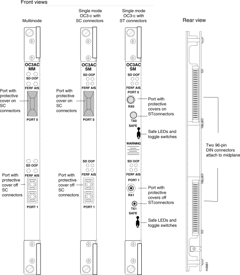
The power loss budgets for OC-3c connections are as follows:
Higher loss, which could result from passing the signal through overly long cables or through too many connectors, may cause signal attenuation and data loss.
Each port on the single mode version of the OC-3c access card with ST connectors has a toggle switch that turns the transmit laser on and off. For the card to function properly, the transmit laser should be turned on. Tests confirm that the amount of laser energy transmitted by this card is not dangerous.
We recommend that you attach a protective cover to any OC-3c port that will be unconnected for more than a brief period. (Covers are shipped with each OC-3c card.) The cover protects the optical media from dust and damage, which can cause signal attenuation and data errors.
Cell-based E3 access cards (which are labelled E3AC) operate in conjunction with cell line cards. The E3AC is available as a 4-port card for edge or trunk connections.
Figure 2-4 shows front and rear side views of the E3AC.
For each port, the E3AC has two SMB connectors. One connector is for the receive channel and one is for the transmit channel; this results in a total of 8 connectors. Each connector is cabled to a 75-ohm BNC coaxial connector on the fantail that provides G.703-compliant connections.
Each access card contains internal DSU/CSUs that can connect directly to an E3 line. E3 access card ports can also connect LS2020 nodes directly at distances up to 1250 feet (381 meters).
The E3AC supports either G.804 or PLCP. The framing method is under software control.
The LEDs on the E3AC are described in the appendix "LEDs."
T3 access cards (which are labelled T3AC) operate in conjunction with cell line cards. T3ACs are available in two versions:
Note The 8-port T3AC requires the 2-TSU cell line card. The 4-port T3AC can use either the 1-TSU or 2-TSU cell line card.
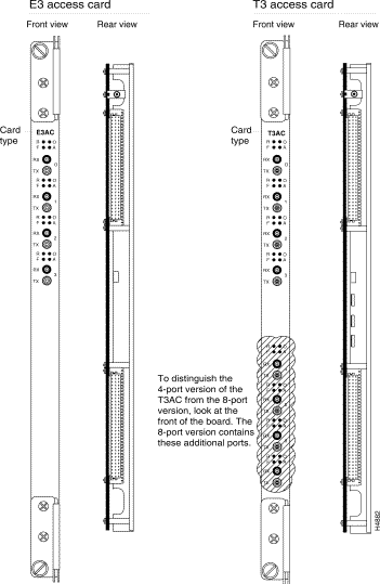
For each port, the T3AC has two SMB connectors. One connector is for the receive channel and the other is for the transmit channel; this results in a total of 16 connectors on an 8-port T3AC and 8 connectors on a 4-port T3AC. Each connector is cabled to a 75-ohm BNC coaxial connector on the fantail that provides DS3-compliant connections.
Each access card contains internal DSU/CSUs that can connect directly to a leased T3 line. T3 access card ports can also connect LS2020 nodes directly at distances up to 900 feet (274 meters).
The LEDs on the T3AC are described in the appendix "LEDs."
Figure 2-4 shows front and rear views of the T3AC.
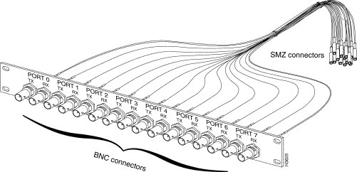
Certain interface modules support more ports than can be accommodated on the access cards. T3/E3 fantails (see Figure 2-5) provide ports for cell line card/T3 modules and cell line card/E3 modules.
Two T3/E3 fantails are available: A four-port version and an eight-port version
The fantail has 8 or 16 BNC connectors—one for transmitting (TX) and one for receiving (RX) on each port. The fantail measures 1.75 inches (1 rack unit, or 4.5 cm) high by 19 inches (48.3 cm) wide. It is designed to fit standard 19-inch equipment racks. Each T3/E3 fantail includes a special cable harness to connect the fantail to its access card.
| Caution The cables attached to the T3/E3 fantail are delicate. If they are allowed to hang unsupported, the weight of unconnected cables can damage cables already connected to the access card. As you connect the cables to the access card, support the loose cables. Tie any unused cables to the rack. In addition, to avoid damaging coax cables, do not bend them more than 90 degrees. |
Depending on the type of access card used, the packet line card (PLC) supports up to eight full duplex ports with over 100 Mbps of continuous aggregate packet bandwidth. The packet line card is shown in Figure 2-6. (For future expansion, the card is designed to accommodate up to 15 ports.)
The PLC supports the following access cards:
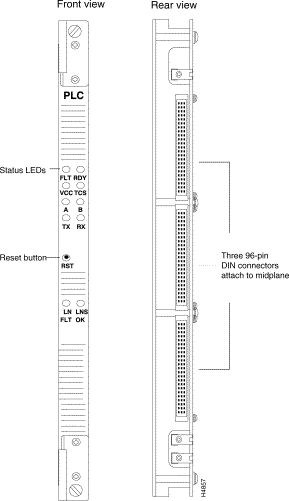
The PLC supports internetworking functions on the LS2020 switch. An important mechanism in this area is the PLC's ability to set up virtual circuits (VCs) on the fly when it encounters streams of traffic not associated with previously known VCs. The PLC's from-line unit (FLU) attempts to recognize incoming traffic as belonging to an established VC. When no match is detected, it buffers the incoming packets of unrecognized traffic and sends the NP the information it needs to set up the VC. Once the setup is complete, the FLU will recognize any subsequent packets for this flow and packet processing proceeds as usual.
The PLC's control processor is a 25MHz Motorola 68EC030 microprocessor. Associated with the control processor are 4 MB of DRAM and 1 MB of flash EPROM that stores bootstrap and POST code. The LEDs for this card are described in the appendix "LEDs."
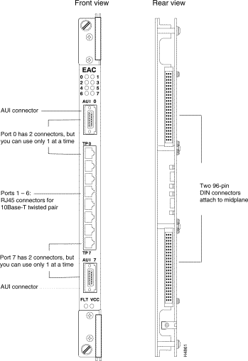
The Ethernet access card (EAC) operates in conjunction with a packet line card. Each EAC supports up to eight IEEE 802.3 Ethernet ports. The ports are of two types:
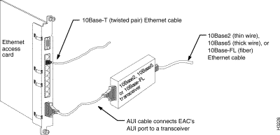
Although it supports eight ports, the access card has 10 I/O connectors. Ports 1 through 6 are female RJ45 connectors that support twisted pair only. Ports 0 and 7 each have two connectors: one female RJ45 for twisted pair connections and one female DB-15 for AUI (attachment unit interface) connections. Only one of the two connectors for each port may be used at a time.
A line attached to a twisted pair port on the EAC must be connected to a 10Base-T hub or concentrator. As shown in Figure 2-7, a line attached to an AUI port must be connected to a 10Base2, 10Base5, or 10Base-FL transceiver, or medium attachment unit (MAU).
The LEDs on the EAC are described in the appendix "LEDs." Figure 2-8 shows the front and rear view of an Ethernet access card (EAC).
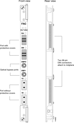
The fiber Ethernet access card (FEAC) operates in conjunction with a packet line card. Each fiber Ethernet access card supports up to eight 802.3 Ethernet 10Base-FL ports. Figure 2-9 shows front and rear views of the card. For each port, the FEAC has two ST connectors that support a multimode fiber interface. One connector is for the receive channel and the other is for the transmit channel; this results in a total of 16 connectors on the FEAC.
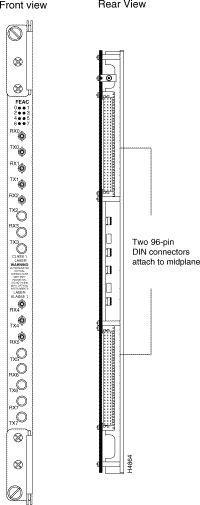
A line attached to a 10Base-FL port must be connected to a 10Base-FL hub or concentrator. The receive channel on the FEAC connects to the transmit channel of the hub or concentrator, and the transmit channel on the FEAC connects to the receive channel of the hub or concentrator. The LEDs on the FEAC are described in the appendix "LEDs."
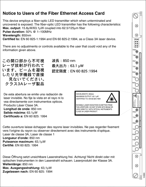
| Warning Unterminated optical connectors may emit radiation. Do not view them with an optical instrument. The transmit laser can damage your eyes. Be sure to read the information contained in Figure 2-10. |
The power loss budget for LS2020 fiber Ethernet connections is 12.5 decibels (dB). Higher loss, which could result from passing the signal through overly long cables or through too many connectors, may cause signal attenuation and data loss.
We recommend that you attach a protective cover to any fiber Ethernet port that will be unconnected for more than a brief period. (Covers are shipped with each fiber Ethernet card.) The cover protects the optical media from dust and damage, which can cause signal attenuation and data errors.
The FDDI access card (FAC) operates in conjunction with a packet line card. It allows the LS2020 node to connect to any network compliant with the ANSI standards for FDDI. Figure 2-11 shows front and rear views of the FDDI access card.
The LEDs on the FDDI access card are described in the appendix entitled "LEDs."
Each FDDI access card supports two multimode FDDI ports. Each port supports a single-MAC station that can function in either dual-attached mode or dual-homed mode. The station management task (SMT) facility adheres to SMT version 7.3 as defined in ANSI X3T9.5.
Each port consists of two media interface connectors (MIC), keyed and labelled as MIC A and MIC B. One 6-pin DIN connector per port is provided for an optional optical bypass cable. This connector lets you attach an external optical bypass relay to provide additional fault tolerance in the dual ring. The FAC senses the presence of the optical bypass relay and switches it in or out at the appropriate times.
The power loss budget for LS2020 FDDI connections is 11 dB. Higher loss, which could result from passing the signal through overly long cables or through too many connectors, may cause signal attenuation and data loss.
We recommend that you attach a protective cover to any FDDI port that will be unconnected for more than a brief period. (Covers are shipped with each FDDI card.) The cover protects the optical media from dust and damage, which can cause signal attenuation and data errors.
The FAC has two CAM (content-addressable memory) chips that filter out incoming packets that are addressed to stations on the same FDDI ring as the LS2020 FDDI interface (and hence do not need to be bridged). The CAMs relieve the packet line card of much of the filtering load.
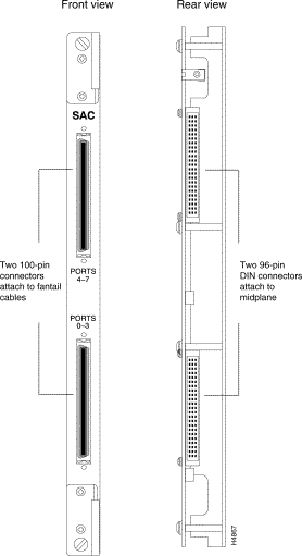
The serial access card (SAC) operates in conjunction with the packet line card. It supports up to eight full-duplex serial I/O ports that can be Frame Forwarding ports, Frame Relay ports, or a combination of the two. To accommodate those ports, the card has two 100-pin connectors. These connectors can be attached to interface-specific fantails (V.35, RS-449, or X.21) that hold the connectors for the I/O ports.
Figure 2-12 shows front and rear views of the card.
The SAC has a group of user-settable jumpers that allow you to select the card's interface type (V.35 or RS-449/X.21). For instructions on setting the jumpers, see the section "Setting SAC Interface Jumpers" in the "Hardware Configuration" chapter.
Access to T1 (DS1) or E1 lines is accomplished through the use of external data service units and channel service units (DSU/CSUs) connected to RS-232 ports on theV.35 or RS-449 fantails. DSU/CSUs are used primarily for long-distance connections with leased lines. A DSU/CSU is not generally necessary for connection to a device in the same building. It is the responsibility of the customer to provide DSU/CSUs; they are not available from Cisco Systems, Inc.
Line speed can be set to selected rates ranging from 55,854 bits per second (bps) up to a maximum of 6,144,000 bps, or to the rates supported by the external DSU/CSU. This arrangement provides support for fractional T1/E1 services.
Each line on the SAC includes a separate interface to control the external DSU/CSU. The interface allows setting loopbacks and carrier channel access configuration in the case of fractional T1. In addition, the interface is used to query traffic and error statistics as well as alarm conditions for local and remote carrier equipment. The control interface is supported by 9-pin male connectors for each port on the V.35 and RS-449 fantails. (X.21 lines do not require DSU/CSU control ports.)
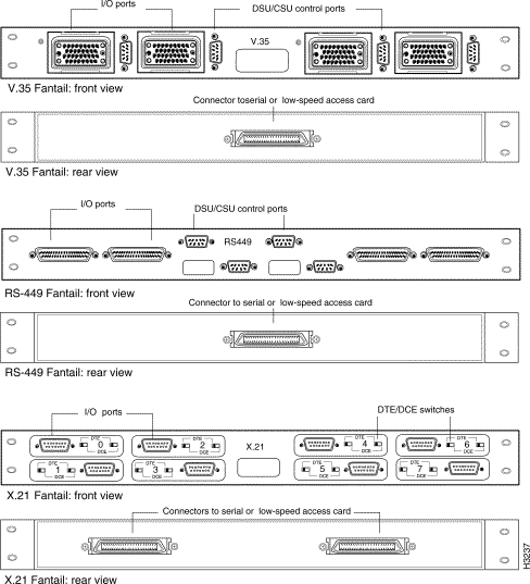
Certain interface modules support more ports than can be accommodated on the access cards. The necessary connectors are provided by fantail devices. Serial fantails (see Figure 2-13) provide ports for serial interface modules and low-speed interface modules. Three types of fantail are available for these modules:
Serial speed fantails measure 1.75 inches (1 rack unit, or 4.5 cm) high by 19 inches (48.3 cm) wide, and weigh 2 lb (0.9 kg). They are designed to fit standard 19-inch equipment racks.
Special 100-pin cables, supplied by Cisco Systems, Inc., are used to connect fantails to SACs and LSACs. To connect a V.35 or RS-449 fantail to its access card, one cable is required. To connect an X.21 fantail to its access card, you can use one or two cables, depending on the number of ports you wish to use.
Each of the connectors on the back of the X.21 fantail (see Figure 2-13) serves four ports on the front of the fantail. (The connector on the left serves ports 0 - 3; the connector on the right serves ports
4 - 7.) If you wish to use up to four ports on the X.21 fantail, you can connect it to the access card with a single cable. If you wish to use 5 or more ports, you must use two cables.
In addition to the four port connectors, each V.35 and RS-449 fantail has four 9-pin male D-type RS-232 connectors for DSU/CSU control ports (also known as craft ports). (X.21 fantails do not have DSU/CSU connectors.) If a port's DSU/CSU control port is connected to an external DSU/CSU device, you can use the csumon utility to set up and monitor the DSU/CSU from the LS2020 switch. See the LightStream 2020 Network Operations Guide for more information on csumon.
Using switches on the X.21 fantail, each X.21 port can be set to either DTE or DCE. The connectors on the fantail are female, the standard for DCE. If you set an X.21 port to be a DTE, you must attach a 15-pin male-to-male gender converter to change the connector on the fantail from female to male.
The X.21 cable available from Cisco Systems, Inc. can be used for both DTE and DCE X.21 ports. See the LightStream 2020 Site Planning and Cabling Guide for information on cables.
The circuit emulation access cards (CEMACs) operate in conjunction with packet line cards. The T1 CEMAC provides eight clear channel DSX-1 constant bit rate (CBR) interfaces at full T1 rates. The E1 CEMAC provides eight clear channel G.704 constant bit rate (CBR) interfaces at full E1 rates. (Fractional circuit emulation is not supported for either T1 or E1.) The CEMAC supports three clocking modes: adaptive, SRTS, and synchronous.
Figure 2-14 shows front, rear, and component side views of the T1 CEMAC. See Figure 5-2 for a similar view of the E1 CEMAC.
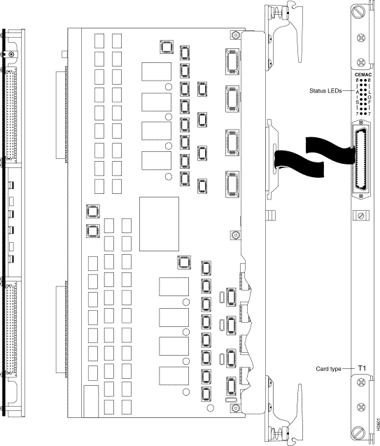
The CEMAC has a single 50-pin Champ (or "telco") I/O connector, to which you attach a fanout device to support up to eight ports. Pinouts and signals for the CEMAC connector are described in the LightStream 2020 Site Planning and Cabling Guide.
The LEDs on the T1 and E1 CEMACs are identical; they are described in the chapter entitled "LEDs." The jumpers on the E1 CEMAC are described in the section "Setting CEMAC Interface Jumpers" in the chapter "Hardware Configuration."
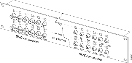
The necessary connectors are provided by fantail devices. The E1 fantail (see Figure 2-15) provides 75-ohm ports for E1 CEMAC modules. The fantail measures 3.27 inches (8.3 cm) high by 19 inches (48.3 cm) wide. It is designed to fit standard 19-inch equipment racks. Two versions of the E1 fantail are available:
Each E1 fantail supports up to 12 ports with 24 connectors—one for transmitting and one for receiving on each port. (E1 fantails currently support a maximum of eight ports because the CEMAC supports a maximum of eight ports.)
For information on the cable used to connect an E1 fantail to a CEMAC and to other devices, see the LightStream 2020 Site Planning and Cabling Guide.
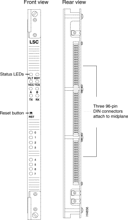
This section describes low-speed line cards. See Figure 2-16 for an illustration.
LS Edge Card—A low-speed line card configured as an edge card provides eight full-duplex serial lines. The card supports frame forwarding and frame relay interfaces, and a single card can have any mix of frame relay and frame forwarding ports. Physical line interfaces include V.35, X.21, and RS-449. Each port on this card operates at speeds up to 3.584 Mbps, although the ports are limited to a maximum aggregate speed of 6 Mbps per line card (regardless of where clock is sourced).
The LS edge card can clock in DCE mode. The card can source clock at the following speeds (bps): 56,000; 64,000; 128,000; 192,000; 256,000; 384,000; 448,000; 512,000; 768,000; 896,000; 1,344,000; 1,536,000; 1,792,000; 2,688,000; 3,584,000; 4,000,000; and 5,376,000.
Each LS edge card requires a low-speed access card for which separate fantails provide V.35, RS-449, or X.21 interfaces.
LS Trunk Card—The LSC configured as a trunk card uses the same hardware as the LS edge card, but different software. The number of ports, physical interfaces, line speeds, external DSU/CSU control ports, and access cards are identical to those for the LS edge card. Instead of handling Frame Relay and Frame Forwarding traffic, the LS trunk card carries ATM cells embedded in HDLC (High-Level Data Link Control) frames.
External DSU/CSU for the LS Line Card—Access to T1 (DS1) or E1 lines is accomplished through the use of external data service units and channel service units (DSU/CSUs) connected to fantails over V.35 or RS-449 serial interfaces. DSU/CSUs are used primarily for long-distance connections with leased lines. A DSU/CSU is not generally necessary for connection to a device in the same building. It is the responsibility of the customer to provide DSU/CSUs; they are not available from Cisco Systems, Inc.
Support of fractional T1/E1 services is provided by allowing line speed settings in selected increments of 56 kilobits per second (kbps) and 64 kbps up to a maximum of T1 and E1 rates supported by the external DSU/CSU.
Each line on the LS line card includes a separate interface to control the external DSU/CSU. The interface allows setting loopbacks and carrier channel access configuration in the case of fractional T1. In addition, the interface is used to query traffic and error statistics as well as alarm conditions for local and remote carrier equipment. The control interface is supported by 9-pin male connectors for each port on the V.35 and RS-449 fantails. (X.21 lines do not require DSU/CSU control ports.)
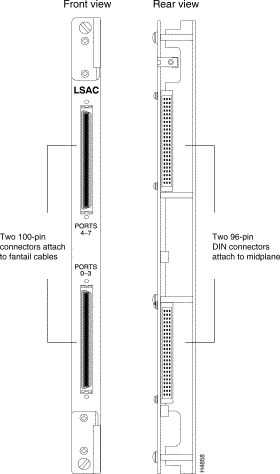
The V.35/RS-449/X.21 low-speed access card (LSAC) operates in conjunction with the low-speed line card. Figure 2-17 shows front and rear views of the low-speed access card.
The card supports up to eight I/O ports. To accommodate those ports, the card has two 100-pin connectors. These connectors can be attached to interface-specific fantails (V.35, RS-449, or X.21) that hold the connectors for the I/O ports.
In conjunction with external DSU/CSUs, low-speed access card ports can be connected to DS1 (T1) or E1 lines.
The low-speed access card has a group of user-settable jumpers that allow you to select the card's interface type (V.35 or RS-449/X.21). For instructions on setting the interface jumpers, see the chapter "Hardware Configuration."
The low-speed access card uses the same fantail as the serial access card. For more information, see the section "Serial Fantail" earlier in this chapter.
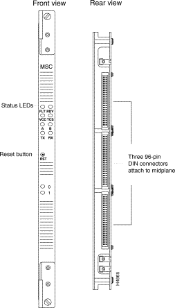
This section describes medium-speed line and access cards. See Figure 2-18 for an illustration of the medium-speed line card. The chief difference between medium-speed edge cards and medium-speed trunk cards is that they use different software. The number of ports, physical interfaces, VCCs, line speeds, and access cards are identical for MS edge and trunk cards.
MS Edge Card—The MSC configured as an edge card provides two full duplex lines, each of which can operate at DS3/T3 (45 Mbps) or E3 (34 Mbps) speeds in each direction.
A single access card for each MS edge card supports two ports. (No fantails are needed for MS edge ports.) Three MS access cards are available; one supports DS3/T3 lines and the other two support E3 lines. The MS edge card handles ATM UNI traffic between the LS2020 network and other ATM devices.
MS Trunk Card—The MSC configured as a trunk card provides two full duplex lines, each of which can operate at DS3/T3 (45 Mbps) or E3 (34 Mbps) speeds in each direction. ATM cells are carried over these lines.
A single access card for each MS trunk card supports two ports. (No fantails are needed for MS trunk ports.) Three MS access cards are available; one supports DS3/T3 lines and the other two support E3 lines. All cards labelled MSC on the bulkhead are functionally equivalent.
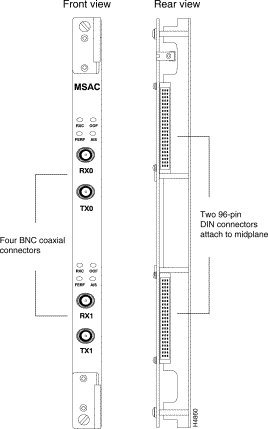
E3 medium-speed access cards (which are labeled MSAC) operate in conjunction with medium-speed line cards. E3 access cards support up to two ports each. Figure 2-19 shows front and rear views of an MSAC.
Each port has two 75-ohm BNC coaxial connectors that provide G.703-compliant connections. One connector is for the receive channel and the other is for the transmit channel.
Each access card contains internal DSU/CSUs that can connect directly to an E3 line. E3 access card ports can also connect LS2020 nodes directly at distances up to 1250 feet (381 meters). Two versions of the E3 access card are offered to support different methods of framing: G.804 and PLCP.
To distinguish between the versions of this card, look at the part number sticker located on the face of the board. The G.804 version of the card has part number 73-1440-xx and the PLCP version of the card has part number 73-1439-xx. The LEDs on the E3 access card are described on in the appendix "LEDs."
T3 medium-speed access cards (which are labeled MSAC) operate in conjunction with medium-speed line cards. T3 MSACs support up to two ports each. Figure 2-19 shows front and rear views of an MSAC.
Each T3 MSAC has four 75-ohm BNC coaxial connectors that provide DS3-compliant connections. Each port consists of two connectors: one for the receive channel and one for the transmit channel.
Each access card contains internal DSU/CSUs that can connect directly to a leased T3 line. T3 access card ports can also connect LS2020 nodes directly at distances up to 900 feet (274 meters).
To distinguish the T3 MSAC from the E3 MSACs, look at the part number sticker located on the face of the board. The T3 MSAC has part number 73-1438-xx. The LEDs on the T3 MSAC are described in the appendix "LEDs."
![]()
![]()
![]()
![]()
![]()
![]()
![]()
![]()
Posted: Wed Jan 22 23:43:12 PST 2003
All contents are Copyright © 1992--2002 Cisco Systems, Inc. All rights reserved.
Important Notices and Privacy Statement.