|
|

This chapter tells you how to perform configuration tasks for a LightStream 2020 multiservice ATM switch (LS2020 switch). It tells you how to create configuration objects (chassis, cards, and ports), how to provision for permanent virtual circuits (PVCs), and how to configure virtual LAN internetworking attributes. It also describes general database management functions, such as saving and backing up the global database and updating a local database.
This chapter does not define configuration attributes, nor does it recommend attribute settings: that material is provided in the following chapter, "Configuration Attributes."
To create a new configuration, you need information on each LS2020 switch. If the switch is already installed in the network, you can use the configurator's Verify function to obtain default settings for many attributes. The section entitled "Verifying a Database" later in this chapter has information on the verification procedures.
If the switch is not installed, you need to consider the following points:
Now you are ready to use the configurator to create and load a configuration database.
The StreamView configurator includes three separate configuration programs:
All of the configuration programs read from and write to the same database. A locking mechanism allows only one configurator to write to the global database at a time. (See the section entitled "Overriding a Configurator Lock " later in this chapter for information on the locking mechanism.)
You can start and run the configurator under HP OpenView or without it. The following sections describe both procedures.
You start each of the three configuration programs in much the same way. In the following procedure, Node Configure is used as an example, with any differences being noted. The assumption here is that HP OpenView is installed and functioning properly.
To start the configurators, use the following procedure:
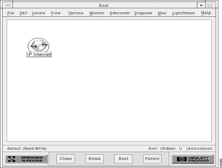
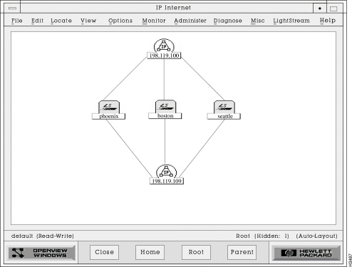
Step 2 Pull down the LS2020 menu on the menu bar, and click on Node Configure, PVC Configure, or VLI Configure.
Step 3 Select the database access mode on the pop-up dialog box that is displayed. If you select read/write, the database is locked to other users and you can make changes to the database file. If you select read only, the file is not locked but you can only examine the settings in the file. If the configurator reports that someone else is using the database, see the section entitled "Overriding a Configurator Lock " later in this chapter before proceeding.
Note The configurator automatically opens the default database file (defined by the LSC_DATABASE variable that is set during installation). You can open a different file, such as a backup file, using the procedure in the section entitled "Opening a Database File " later in this chapter.
To start the configurators without HP OpenView, use this procedure:
Step 2 Select the database access mode on the resulting pop-up dialog box. If you select Read/Write, the database is locked to other users, and you can make changes to the database file. If you select Read Only, the file is not locked, and you can only examine the settings in the file. If the configurator reports that someone else is using the database, see the section entitled "Overriding a Configurator Lock " later in this chapter before proceeding.
Note The configurator automatically opens the default database file that is set during installation. You can open a different file using the procedure in the section entitled "Opening a Database File " later in this chapter.
Table 3-1 summarizes steps for performing some frequently used configuration procedures.
Note The configurator uses standard Motif conventions for the graphical interface. See your Motif documentation for more detailed information.
Table 3-1 Frequently Used Configuration Procedures
Once you start the configurators, you can make entries or changes in the global configuration database. The information is not written to the global database until you perform the save operation. The save operation is discussed in the section entitled "Saving or Aborting Changes " later in this chapter. Information from the global database is not sent to a switch until you specify an update time.
This section tells you how to create and configure an LS2020 chassis object, starting at the Node Configurator dialog box. Use the Node Configure tool (cfg) to create a chassis object.
Note In order for the configurator to be able to access an LS2020 node through IP, your network administrator must establish and maintain the /etc/hosts file on the Sun workstation running the configurators. This file correlates the LS2020 node name with an IP address and is needed for communication between the NMS and the switches.
You can create a configuration file for a node before or after it is installed. In either case, the name given to the chassis during installation should be the same name used during configuration and the same name that is entered in the /etc/hosts file. (A chassis can be configured with the IP address being used as a name if the /etc/hosts file or name server is not available.)
Note This section does not give recommended settings nor does it describe the various attributes that you can configure using this procedure. See the following chapter, "Configuration Attributes," or the online help for that type of information.
In the Node Configurator dialog box (Figure 3-4), the Chassis Name list box gives the names of all LS2020 chassis that are currently entered in the global database file. This does not mean that the chassis have been installed; it simply means that someone has used the configurator to create database entries for them.
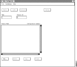
Here are the steps for creating a node configuration file. The attributes used in this task are described in the following chapter in the section "Chassis Attributes."
Step 2 If the chassis has not been installed yet, click in the Chassis ID field box and type in a unique ID number. You can use a temporary number. (Once the chassis is installed, you can use the Verify function to get the actual ID number.)
Step 3 Click on the Add push button, and the new chassis name is added to the list.
Step 4 Click on the entry in the Chassis Name list to select the chassis you are going to configure.
Step 5 If you are configuring a chassis that has already been installed, you can use the Verify function to retrieve the configuration attributes that were entered during installation (or set to default values by the software). This saves you from having to re-enter that information. The Verify function is discussed later in this chapter under the heading "Verifying CFG Attributes."
Step 6 Click on the Chassis button to reach the Chassis Configuration dialog box (Figure 3-5).
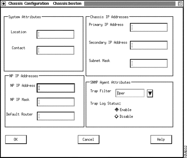
Step 7 The dialog box provides field boxes for the primary and secondary IP addresses, IP subnet mask, NP (Ethernet) IP address, NP IP subnet mask, and default router address attributes. You must set a primary IP address and subnet mask. Set any other address or mask attributes as required. (If you want more information on the attributes, click on the Help button.)
Step 8 The dialog box also contains two optional attributes, system contact and system location. Make entries as desired.
Step 9 You can set SNMP agent attributes in this dialog box: you can set the trap filter level or enable or disable the trap log.
Step 10 To store the changes you have made in this dialog box, click on the OK button. This returns you to the Node Configurator dialog box.
You have now created and configured a chassis object; you can go on to configure card objects, or you can delete, copy, or rename a chassis.
To delete a chassis, use the following procedure:
Step 2 Click on the Delete button.
Step 3 A pop-up dialog box is displayed asking if you want to delete the chassis. Click on the OK button to delete the chassis. The record is deleted and the entry is removed from the Chassis Name list. (Click on the Cancel button if you do not want to delete the chassis.)
Note You cannot delete a chassis that has been configured with PVCs. You must delete the PVCs and update the chassis before you can delete the chassis.
To copy a chassis, use the following procedure:
Step 2 Click on the Copy button. A pop-up dialog box is displayed.
Step 3 Enter a new chassis name and chassis ID in the field boxes provided. Make entries for the NP IP address and for the primary and secondary IP addresses.
Step 4 Click on the OK button to copy the chassis. All chassis, card, port, and bridging attributes are copied to the new chassis, and the entry is added to the Chassis Name list. (Click on the Cancel button if you do not want to copy the chassis.)
Step 5 Rename the cards and ports, if desired. The configurator does not do this for you.
To rename a chassis, use the following procedure:
Step 2 Click on the Rename button. A pop-up dialog box is displayed.
Step 3 Enter a new chassis name in the field box provided.
Step 4 Click on the OK button to rename the chassis. The new chassis name is added to the Chassis Name list, and the previous name is removed. (Click on the Cancel button if you do not want to rename the chassis.)
Note When you rename a chassis, the PVC and VLI attributes associated with the chassis are retained. You do not have to re-enter them.
This section describes the procedure for creating and configuring database objects for the following kinds of LS2020 card:
The NP has no ports and must be inserted in slot 1. (If you have a backup NP, insert it in slot 2.) The NP receives little attention in this manual because it lacks edge and trunk connections and so differs from the other cards discussed here. Switch cards have no configurable attributes and thus are not listed here at all.
Before executing this procedure, you must have created a chassis object. In this procedure, you are assumed to be starting out in the Node Configurator dialog box (Figure 3-4), where the last procedure, Creating a Chassis, ends.
Before you configure any cards, you need to know what cards are installed, their slot numbers, and their special (nondefault) configuration attributes. You use this information as you create the configuration file. If the switch has already been installed, you can use the Verify button on the Node Configurator dialog box to retrieve card configuration information from the switch. The information was entered during installation or set to default values by the software.
To configure cards, use this procedure. The attributes used in this task are described in the next chapter in the section "Card Attributes."
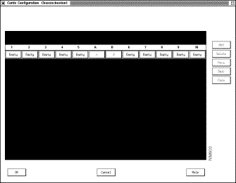
Note The NP card normally occupies slot 1; slot 2 holds either a backup NP card or a line card. Slots 3 through 10 are for line cards only. Slots A and B are for switch cards.
Step 2 Click on the push button below the number of the slot that you want to configure. This button is labeled Empty, or, if it has been previously configured, it is labeled with an abbreviation for the card type. After you click on a push button, card configuration attributes are displayed across the top of the dialog box (see Figure 3-7).
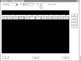
Step 3 To select a card type, pull down the Type button and click on the desired card type. The list closes, and the selected type is displayed on the Type option button.
Step 4 You can enter a name for the card by clicking in the Name field and then typing a name. (Naming a card is optional. Choose a name with no more than 19 characters, and do not use a name that begins with a number or includes quotation marks.) If you do not enter a name, the configurator provides a default name, which uses the switch name as a base. For example, if the chassis name is Boston1, the default name for the card in slot 4 is Boston1.4.
Step 5 To change the administrative status of a card, click on the appropriate radio button. The default card status is up. It is usually best to leave the status set to up in the configuration.
Step 6 To change the maximum number of virtual circuits allowed on the card, click on the Expert radio button. A default value is provided for this attribute, and in most cases you should not change it.
Step 7 Click on the Add push button. The push button below the slot number is filled in with an abbreviation for the card type that you configured. Push buttons (labeled with question marks) appear in the corresponding slot, the number of push buttons displayed indicating the number of ports available for that type of card.
You have now created and configured a card object. You can delete, move, swap, or copy a card, or you can create ports on the cards that you have configured.
To delete a card and its associated ports, use this procedure:
Step 2 Click on the Delete button. The card name disappears from the button and is replaced with the word Empty, and any port icons are removed.
Note If any PVCs are configured for the card, they must be deleted and the switches must be updated before you can delete the card.
To move a card and its associated ports from one slot to another, use this procedure:
Step 2 Click on the Move button. The dialog box displays the Selected Destination Slot field (see Figure 3-8).
Note If any PVCs are configured for the card, they must be deleted and the switches must be updated before you can move the card.
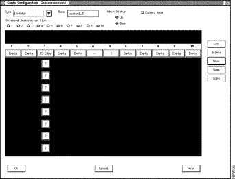
Step 3 Click on the radio button labeled with the destination slot number, and the dialog box is updated to show the card in its new slot. The old slot is labeled Empty.
Step 4 Rename the card and its ports, if desired. The configurator does not do this for you.
To swap two cards and their associated ports between slots:
Step 2 Click on the Swap button. The dialog box displays the Selected Destination Slot field.
Step 3 Click on the radio button labeled with the destination slot number, and the dialog box is updated to show the cards in their new slots.
Step 4 Rename the card and its ports, if desired. The configurator does not do this for you.
To copy a card and its associated ports to a slot:
Step 2 Click on the Copy button. The dialog box displays the Selected Destination Slot field.
Step 3 Click on the radio button labeled with the destination slot number. The dialog box is updated to show the same type of card and ports in the new slot.
Step 4 It is advisable to rename the card and its ports. (This eliminates the confusion that could easily result from the use of duplicate names.) The configurator does not do this for you.
This section explains how to create and configure LS2020 ports with the CiscoWorks StreamView configurator. A port's type is determined by its configuration settings and its interface module (line card and access card combination). To configure a port, you first select a card type in the Cards Configuration dialog box. This gives you access to individual port attributes.
The configurator card type names do not correspond directly to interface module names. Table 3-2 matches port types and interface modules with configurator edge card types. Table 3-3 matches port types and interface modules with configurator trunk card types.
Table 3-2 Configuring Edge Ports
| If you want to configure this type of port | And you have this type of interface module | You select this type of card in the configurator |
Table 3-3 Configuring Trunk Ports
Before creating a port, you must create at least one chassis object and one card object. The card must be the type that is appropriate for the port you want to create (see Table 3-2 and Table 3-3). (For example, if you want to create a frame relay port, you can select LS-Edge or SAC-Edge as the card type.)
If you are configuring the switch before it has been installed, you need to create the configuration file, where you enter the port types for each card as well as the card's nondefault configuration attributes. If the switch has already been installed, you can use the Verify function to retrieve previously set card and port configuration information. This information might have been entered during switch installation, or it could be based on default software values.
Be aware of two conventions used by the configurator, regardless of the type of port you are configuring:
The following procedure is for the creation of trunk and edge ports. The general procedure is the same, regardless of the interface type; only the attributes vary.
The port configuration procedure begins in the Cards Configuration dialog box. Figure 3-9 shows the Cards Configuration dialog box, configured with many of the card types described in this section.
Note Configure port 0 on all cards, even if it is not going to be used. Card type is derived from the setting for the lowest configured port. Configuring an unused port does not affect system operation.
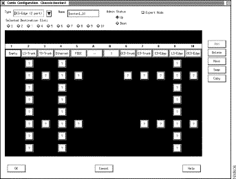
To create a trunk or edge port, use this procedure. The attributes used in this task are described in the next chapter in the section "Port Attributes."
Step 2 You can use the default name or enter a name for the port. (Naming ports is optional. Choose a name with no more than 19 characters, and do not use a name that begins with a number or includes quotation marks.)
Step 3 Examine the other default values and reset any that require adjustment. Click on the OK button at the bottom of the dialog box; you are returned to the Card Configuration dialog box. If you need information on attributes, click on the Help button on the dialog box or refer to the following chapter, "Configuration Attributes."
You have now finished configuring the physical-level components for your switch: chassis, cards, and ports. You can go on to configure network-level attributes (such as bridging and filtering) and internetwork-level attributes (such as PVC and VLI).
To change any port type except the LSC edge port, you must delete the card that the port is on, create the desired card type, and then configure the ports. For instance, to change an E3 edge port to an E3 trunk port, you must
1. Delete PVCs associated with the port and update the switches
4. Configure the E3 trunk ports
When you are changing between a frame relay port and a frame forwarding port on an LSC edge card, you must
1. Delete PVCs associated with the port and update the switches.
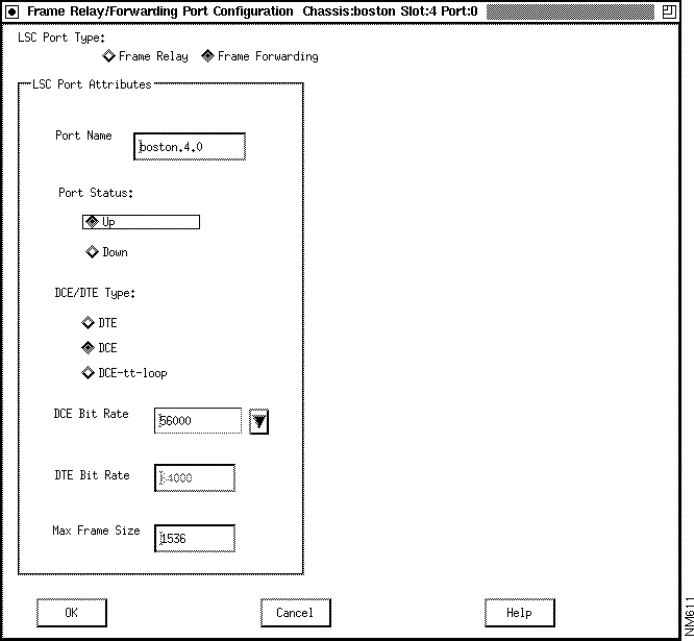
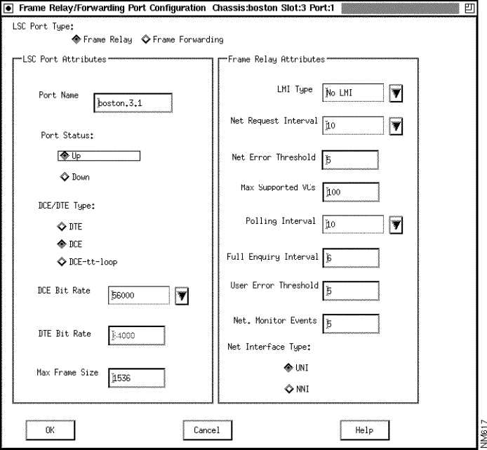
2. Click on the appropriate radio button at the top of the Frame Relay Port Configuration or Frame Forwarding Port Configuration dialog box. Figure 3-14 shows the frame forwarding port configuration dialog box, and Figure 3-15 shows the frame relay port configuration dialog box.
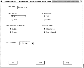
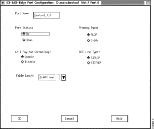
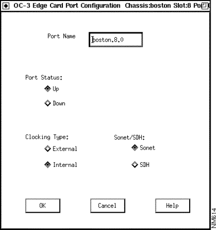
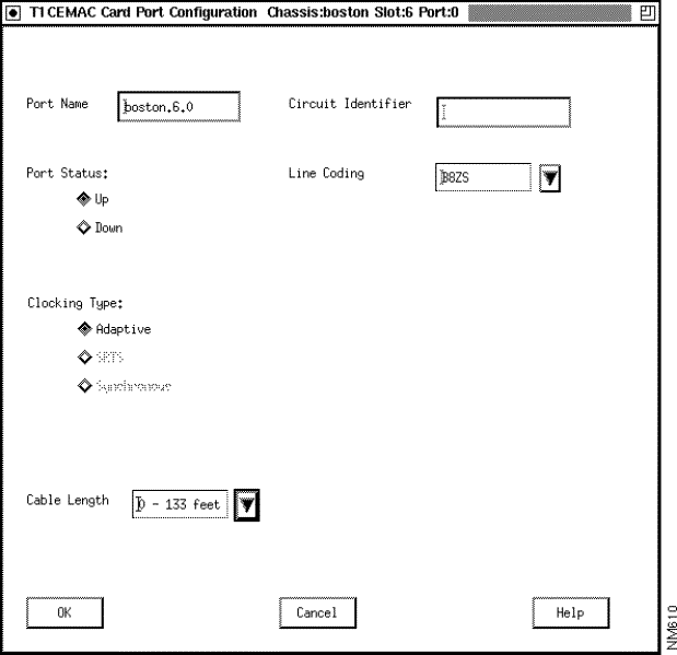
The screens in Figure 3-10 through Figure 3-13 show the trunk port dialog boxes.
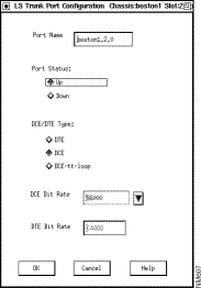
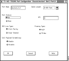
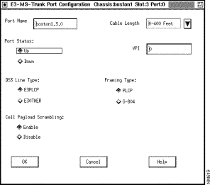
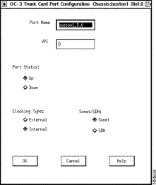
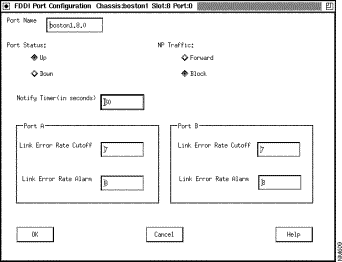
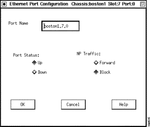
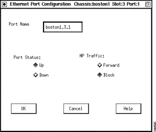
The screens in Figure 3-14 through Figure 3-22 show representative edge port dialog boxes. The full listing of all edge port types is available in the Type list box in the Cards Configuration dialog box. The following chapter, "Configuration Attributes," gives details about all fields for all cards.
At the top left of the Frame Relay/Frame Forwarding Port Configuration dialog box, there are two radio buttons for selecting frame relay and frame forwarding. Frame relay is the default setting. If you want to configure a frame forwarding port, click on that radio button; the dialog box is changed to show frame forwarding attributes. Figure 3-14 shows the frame forwarding dialog box, and Figure 3-15 shows the frame relay dialog box.
This procedure explains how to configure a prioritized list of timing sources for the node. This list, called the Preference Table, holds up to ten entries. The entries are listed in order from most desirable timing source to least.The Nettime (network timing) attributes are described in the next chapter in the section "Nettime Attributes."

Step 2 In the upper right corner of the Cards Configuration dialog box, click on the Nettime push button. The Nettime dialog box (Figure 3-24) appears. (If the Nettime button is grayed out, the system has detected one or more Release 1 switch cards in the target node and the network timing feature is therefore unavailable.)
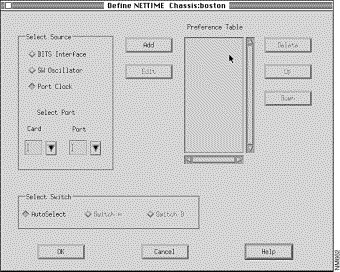
Step 3 To add an entry to the Preference Table, click on one of the timing sources in the Select Source portion of the dialog box. If you select BITS Interface or SW Oscillator, click on the Add button to add that source to the Preference Table. If you select Port Clock, you must specify the card and port from which the timing will be derived. Then click on the Add button to add that source to the Preference Table.
To delete an entry from the Preference Table, select it and click on the Delete button.
To move an entry up or down in the Preference Table, select it and click on the Up button or the Down button.
To replace an entry with a different entry in the same position in the Preference Table, select the entry. In the Select Source portion of the dialog box, click on the radio button for the replacement entry. Then click on the Edit button. The old entry is replaced with the new one in the Preference Table.
Step 4 In the Select Switch portion of the dialog box, you can select the switch card that will provide clocking to the node: Switch A, Switch B, or Autoselect.
If you have configured any FDDI or Ethernet ports (including fiber Ethernet ports) in your network, you can configure
The following sections describe the procedures you use to configure each of these entities.
Use the following procedure to configure spanning tree bridge attributes. The spanning tree bridge attributes are described in the following chapter, in the section "Spanning Tree Attributes."
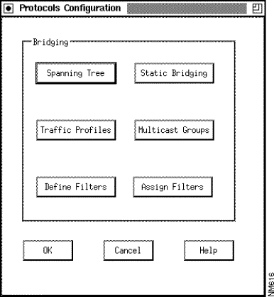
Step 2 Click on the Spanning Tree button. A dialog box like the one shown in Figure 3-26 is displayed.
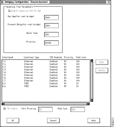
Step 3 The Spanning Tree Parameters portion of the dialog box defines chassis-level bridging attributes. To change an attribute, click in the field box and type in a new value.
Step 4 The Interface list in the lower half of the dialog box displays all configured bridge ports on the chassis with their default settings. If you want to change a value, click on a port to select it, and then type in the Port Priority or Path Cost field box to set the value for the port. You can also enable or disable spanning tree bridging on a per-port basis by clicking on the STB Enable check button.
Step 5 Click on the Edit button to store the changes. The parameters in the list box are updated to reflect the newly entered values.
Step 6 Repeat Step 4 and Step 5 for any other ports that have values you want to change.
Step 7 Store the changes you have made to this dialog box by clicking on the OK button. (You can also click on the Cancel button to discard the changes.)
You can use the custom filters capability to set up multiple per-port filters on a chassis. The filters applied to a port determine the action taken on incoming frames at that port.
You create custom filters on a per-port basis. Creating a custom filter consists of defining the filter and then assigning the filter to a port or ports. You can assign multiple filters to one port, and you can assign the same filter to multiple ports.
Before you can create custom filters, you must configure a chassis. Before you assign the filter to a port, you must configure at least one FDDI, Ethernet, or fiber Ethernet card with its associated ports.
Note Filters are optionally used to identify a flow for traffic profiles and multicast groups. (A filter can, of course, be used without a traffic profile or a multicast group.) The filter is assigned to the port where the traffic profile or multicast group is to be created. The profile or multicast group is thus said to be assigned to a filter-port pair. The filter specifies the packets to which the multicast group or traffic profile applies.
Use the following procedure to define a filter. The custom filter attributes are described in the following chapter in the section "Custom Filter Attributes."
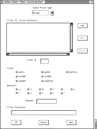
Step 2 In the Select Filter Type box, select the type of filter you want to create. The types are Bridge, IP, and IPX. Notice that the values in the Fields and Operators portions of the screen change according to the type of filter you specify.
Step 3 Enter an ID in the Filter ID box.
Step 4 Create the filter expression in the Filter Expression field by entering fields, constants, and operators in the Filter Expression field box. You can enter a maximum of 250 fields, constants, and operators. There are two ways to enter the values that you want to use:
Note In the Filter Expression field box, you can use the Backspace key to delete characters and the left and right arrows on the right keypad to move through the text. In the Filter Expression box, you can double-click on a constant, field, or operator to select it, or you can press the first mouse button and, while holding the button down, drag past the characters you want to select. You can then delete the selected characters.
Step 5 To add the filter you have defined, click on the Add button; the Filter ID list is updated with the new filter. (Be sure to click on Add rather than on OK. If you click on OK rather than Add, the filter you just defined disappears and you are returned to the Protocols Configuration dialog box.)
The dialog box in Figure 3-28 shows a switch that has been configured with a single custom filter (macProto == 6004).
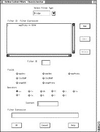
The procedure for entering the filter shown in Figure 3-28 has five steps:
Step 2 Click on the macProto radio button. macProto is added to the Filter Expression box.
Step 3 Enter 6004 in the Constant field box.
Step 4 Click on the == radio button and ==6004 is added to the Filter Expression box.
Note A constant is a decimal value by default unless it is preceded by 0x, in which case it is hexadecimal. Exceptions here include macDest and macSrc in the bridge category and ipxSrcNd and ipxDstNd in the IPX category.
Step 5 Click on the Add button to update the Filter ID list with the new filter.
Now you can assign the filter to a port, using the procedure described later in this chapter under the heading "Assigning a Filter ." (A defined filter does not take effect until it has been assigned to a port.) If you are not going to assign any filters right now, you can keep the changes you have made in this dialog box by clicking on the OK button at the bottom of the dialog box. (You can also click on the Cancel button to discard the changes.)
To edit or delete a filter, use the Define Custom Filters dialog box (Figure 3-27). To edit an existing filter, use this procedure:
Step 2 Change the expression in the Filter Expression field box as desired.
Step 3 Click on the Edit button. The Filter ID list is updated with the changed filter.
To delete an existing filter, use this procedure:
Step 2 Click on the Delete button. The filter ID is removed from the Filter ID list.
If you want to assign an edited filter to a port, use the procedure described in the next section. If you are not going to assign any filters right now, you can keep the changes you have made to this dialog box by clicking on the OK button at the bottom of the dialog box. (You can also click on the Cancel button to discard the changes.)
After you have created or modified a filter, you can assign it to a port or to multiple ports. The attributes used in this task are described in the following chapter in the section "Assigning Filters." To assign a filter, use this procedure:
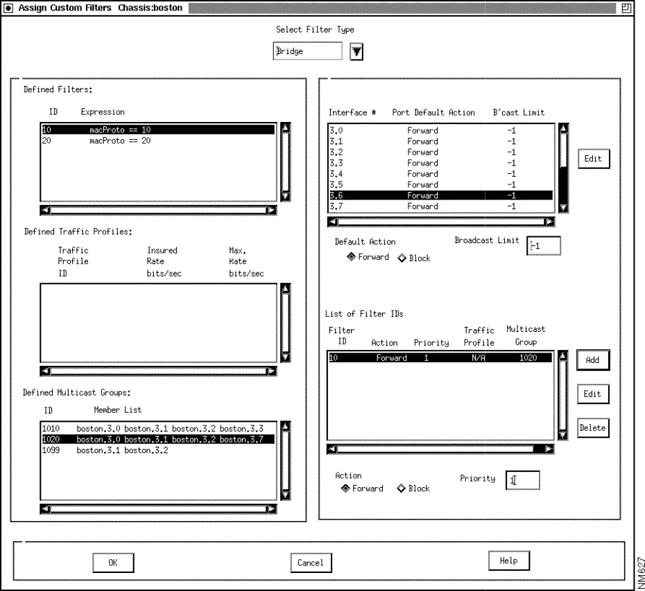
Step 2 In the list at the top of the screen, select the type of filter you want to assign.
Step 3 In the list of interfaces, click on the interface for which you want to assign a filter.
Step 4 In the Defined Filters list, click on the ID for the filter you want to assign.
Step 5 Below the List of Filter IDs, select Forward or Block.
Step 6 Enter the priority of the filter. Filters are executed in order of their priority settings. The lowest numerical value has the highest priority.
Step 7 Click on the Add button next to the list of filter IDs. The filter is assigned to the interface and is displayed in the list of filter IDs.
Step 8 Repeat the procedure in Step 2 through Step 7 for as many filters as you want to assign to the interface.
Step 9 When you are finished, click on the OK button at the bottom of the Assign Custom Filters screen. This assigns the filter(s) to the selected port(s). You are returned to the Protocols Configuration screen.
You have now defined and assigned your per-port custom filters. You can store the changes you have made in this dialog box by clicking on the OK button. (You can also click on the Cancel button to delete these changes.) Remember that these values are not written to the global database until you perform a Save operation (see the section entitled "Saving or Aborting Changes " later in this chapter).
After you have assigned a filter to a port, you can change its Action or its Priority setting, or you can remove it from among the active filters for the port. To edit a filter or cancel its assignment to a port, use the Assign Custom Filters dialog box (Figure 3-29).
To edit the filter, use this procedure:
Step 2 In the List of Filter IDs, click on the desired filter.
Step 3 You can change the Action or Priority setting and then click on the Edit button.
Step 4 To store the change you have made, click on the OK button at the bottom of the dialog box. (You can also click on the Cancel button to delete your change.)
To remove a filter from a port, use this procedure:
Step 2 In the List of Filter IDs, click on the desired filter.
Step 3 Click on the Delete button. The filter is removed from the list.
Step 4 To store the change you have made, click on the OK button at the bottom of the dialog box. (You can also click on the Cancel button to delete your change.)
You can use the Traffic Profiles option to set up one or more traffic profiles on a chassis. A traffic profile is a network-wide construct. After you define a profile, you can assign it to one or more ports.
Before you can create a traffic profile, you must configure one chassis and at least one FDDI, Ethernet, or Fiber Ethernet card with its associated ports.
To define a profile, use this procedure. The attributes used in this task are described in the following chapter in the section "Traffic Profiles."
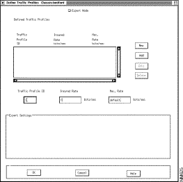
Step 2 Enter an ID, an insured rate, and a max rate for the profile, using the fields below the Traffic Profile list box. If you are an expert user, go to Step 3. Otherwise, go to Step 5.
Step 3 Click on Expert Mode. Five more options are displayed in the Expert Settings box.
Step 4 Choose values for the five Expert Settings options: Insured Burst, Max. Burst, Secondary Scale, Principal Service Type, and Transmit Priority.
Step 5 To enter the new traffic profile, click on the Add button. The profile appears in the Defined Traffic Profiles list.
Step 6 Repeat the procedure from Step 2 through Step 5 for each traffic profile you want to define.
Step 7 When you have finished defining traffic profiles, click on OK. The profiles are stored. You can also click on Cancel if you decide not to add the profiles you have defined.
You can edit or delete a traffic profile if it is not assigned to an interface. To edit a traffic profile, use this procedure:
Step 2 Make changes to the entries in the boxes below the list.
Step 3 Click on the Edit button. The Traffic Profiles list is updated with the new information.
Step 4 Click on the OK button to save the modified traffic profile information.
If you want to assign the edited profile to an interface, use the procedure described in the next section.
To delete an existing profile, use this procedure:
Step 2 Click on the Delete button. The traffic profile is removed from the Defined Traffic Profiles list.
Step 3 Click on the OK button to save the modified traffic profile information.
After you have created or modified a traffic profile, you can assign it to one or more filter-port pairs. To do so, use this procedure. The attributes used in this task are described in the following chapter in the section "Assigning Filters."
Step 2 In the list of interfaces in the upper right portion of the screen, select the interface for which you want to assign a profile.
Step 3 In the list of defined filters, select the filter that you want to use.
Step 4 In the list of defined traffic profiles, select the profile that you want to assign to the interface.
Step 5 Specify the priority level that you want to assign to this filter.
Step 6 Make sure that Forward is selected in the Action field beneath the list of filter IDs.
Step 7 Click on the Add button. The filter and traffic profile are displayed in the List of Filter IDs.
Step 8 Repeat the procedure in Step 3 through Step 7 for each profile you want to assign.
Step 9 When you have added all of the traffic profiles you wish to use, click on the OK button at the bottom of the screen. Once you click on that button, the traffic profile assignments are saved.
After you have defined a traffic profile and assigned it to a port, you can modify its priority level or cancel its assignment to the port.
Note You cannot modify the profile itself once it has been assigned. If you want to edit an existing profile, you must first cancel its assignment to any port.
To modify the priority level of a filter assigned to the profile, use this procedure:
Step 2 Select an assigned filter from the list of filter IDs. An entry is displayed in the List of Filter IDs showing the ID, priority, and traffic profile you have selected.
Step 3 Enter a new value in the Priority field beneath the List of Filter IDs box.
Step 4 Click on Edit. The new priority is assigned.
Step 5 Click on the OK button at the bottom of the screen to save your changes. Alternatively, you can click on Cancel to return the priority level to its previous setting.
To cancel the assignment of an assigned traffic profile, use this procedure:
Step 2 Select the interface and traffic profile whose priority you want to modify. An entry is displayed in the List of Filter IDs showing the ID, priority, and traffic profile you have selected.
Step 3 Click on the entry for the profile in the List of Filter IDs box.
Step 4 Click on the Delete button. The profile is deleted.
You can use the Multicast Groups option to set up one or more such groups. Multicast groups are network-wide constructs. They can be configured whether or not a chassis has been specified. Once you create a multicast group, you can assign it to one or more interfaces. The group is associated with (assigned to) a filter-port pair.
Use the following procedure to define a multicast group. The attributes used in this task are described in the following chapter in the section "Multicast Groups."
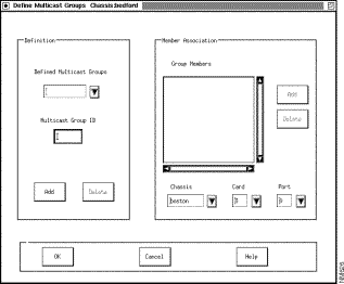
Step 2 Enter an ID for the multicast group you want to define.
Step 3 Click on Add in the Definition portion of the screen.
Step 4 Select a chassis, card, and port from the Member Association portion of the dialog box. This is the interface that you want to put in the multicast group.
Step 5 Click on the Add button in the Member Association portion of the dialog box. The port is entered in the Group Members list box.
Step 6 Repeat the procedure in Step 4 and Step 5 for each port that you want to add to the group.
Step 7 Repeat the procedure in Step 2 through Step 6 for each additional group that you want to define.
Step 8 When you have added all members of all groups that you want to define, click on the OK button at the bottom of the dialog box. Doing so stores your definitions in the database in run-time memory on the management station. You are returned to the Protocols Configuration screen.
After you have defined a multicast group, you can modify it by adding or deleting group members. You can also delete the entire group.
To delete a member from a group, use this procedure:
Step 2 Click on the group member (interface) that you want to delete.
Step 3 Click on the Delete button.
Step 4 Click on the OK button to activate your choice, or click on Cancel if you decide against the deletion.
To add a member to a group, use this procedure:
Step 2 Use the field boxes beneath the Group Members list area to specify the interface (chassis, card, and port) that you want to add to the group.
Step 3 Click on the Add button to the right of the Group Members list.
Step 4 Click on the OK button at the bottom of the screen. The interface that you have specified is added to the group member list.
To assign a defined multicast group to an interface, use this procedure. The attributes used in this task are described in the following chapter in the section "Assigning Filters."
Step 2 In the list of interfaces in the upper right portion of the screen, select the interface for which you want to assign a multicast group.
Step 3 In the list of defined filters, select the filter that you want to use.
Step 4 In the list of defined multicast groups, select the multicast group that you want to assign to the interface.
Step 5 Specify the priority level that you want to assign to this filter.
Step 6 Make sure that Forward is selected in the Action field beneath the list of filter IDs.
Step 7 Click on the Add button. The filter and multicast group are displayed in the list of filter IDs.
Step 8 Repeat the procedure in Step 3 through Step 7 for each multicast group you want to assign.
Step 9 When you have added all of the multicast groups that you want to use, click on the OK button at the bottom of the screen. Once you do that, the multicast group assignments are saved.
Figure 3-32 shows an example of a multicast group assignment. In the figure, multicast group 1020 is assigned to port 6 on card 3 in the chassis named Boston.

To cancel the assignment of an assigned multicast group, use this procedure:
Step 2 Select the interface and multicast group that you want to modify. An entry is displayed in the List of Filter IDs showing the ID, priority, and multicast group that you have selected.
Step 3 Click on the entry for the multicast group in the List of Filter IDs box.
Step 4 Click on the Delete button. The multicast group is deleted.
This section tells you how to create entries for static bridge filters in the bridge's filtering database. (This functionality is specified in IEEE 802.1d-1990.)
The filtering database matches a MAC destination address with (1) an LS2020 port that can receive frames with this MAC destination address and (2) a set of LS2020 ports on which the frames should be transmitted.
The bridge forwarding process uses the entries in the filtering database to determine the forwarding route for frames with a given MAC address. You create static bridge filters on a per-chassis basis.
To create a static bridge filter in the bridge filtering database, use this procedure. The attributes used in this task are described in the following chapter in the section "Static Bridge Filtering."
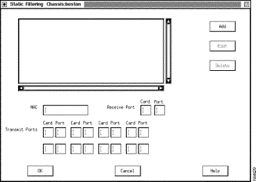
Step 2 Enter the MAC address, the receive port address, and the transmit port address(es) in the field boxes provided.
Step 3 Click on the Add button. The list box is updated with the new static bridge filter.
In the list, the first grouping of numbers is the MAC address. The second is the receive interface (card and port number). The next pair of numbers is the first transmit interface (card number and port number). Any other pairs of numbers are additional transmit interfaces. Figure 3-34 shows a Static Filtering dialog box with two multicast bridge filters defined.
Step 4 Click on the OK button to store the bridge filter.
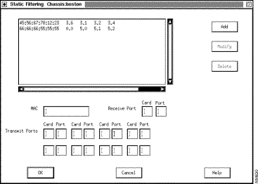
To edit an existing static bridge filter, use this procedure:
Step 2 Make your changes to the values in the individual card and port boxes.
Step 3 Click on the Edit button. The entry in the list box is modified to reflect your changes. (Remember that the first pair of boxes to the right of the MAC address refers to the receive interface.)
Step 4 Click on the OK button to save the changes you have made.
To delete an entire bridge filter, use this procedure:
Step 2 Click on the Delete button.
Step 3 Click on the OK button to confirm the action. The bridge filter is deleted.
You have now defined your per-port static bridge filters. Remember that the values you have entered are not written to the global database until you perform a Save operation (refer to the section entitled "Saving or Aborting Changes " later in this chapter).
In provisioning for PVCs, you must specify the endpoints and the characteristics of the circuit that you want to create. You can use the procedure given here to set up PVCs between
Although PVCs can be created for each of these port types, the circuits created differ in certain respects, depending on the type of card for which they are created (see Table 3-4).
Note To configure a PVC, you must have previously configured the two edge ports that it will connect.
Table 3-4 PVC Characteristics for Various Types of Interface Card
| Type of Card | Type of Circuit ID | Measure of Circuit Capacity | Other Circuit Characteristics |
|---|---|---|---|
To set up a PVC, use this procedure. The attributes used in this task are described in the following chapter in the section "PVC Attributes."
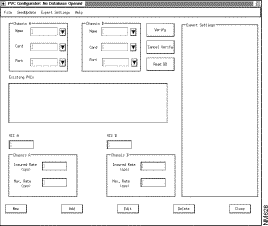
Step 2 Specify a name, card, and port for chassis A.
Note If you started the configurator from the IP Internet map (Figure 3-3) with two chassis selected, the names of those chassis are already in the chassis A and chassis B Name field boxes.
Step 3 Specify a name, card, and port for chassis B.
Step 4 Click on New at the bottom of the screen. The configurator supplies default transmission rates for the type of circuit involved. It also supplies DCLI or VCI values if those are relevant for the circuit.
Step 5 Enter the insured rate and the maximum rate for each chassis. The rates for chassis A need not match those for chassis B. Chassis A attributes are for the VC from chassis A to chassis B. Chassis B attributes are for the VC from chassis B to chassis A.
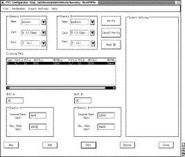
Step 6 Click on Add. Information about the new circuit is displayed in the Existing PVCs list box. Figure 3-36 shows an example of the PVC dialog box with one new frame relay circuit added.
Step 7 To save the PVC you have configured, click on Save from the File pull-down menu. If you do not want to save the circuit configuration, click on the Close button.
If you want to retrieve settings from the local database stored in run-time memory on the nodes, click on the Verify button. (For more information on Verify, see the section entitled "Verifying PVC Attributes " later in this chapter.)
To retrieve the settings in the global database for all PVCs configured between two chassis, use this procedure:
Step 2 Select All in the Card field for each chassis. (All is also displayed in the Port field for each chassis.)
Step 3 Click on the Read DB button. All PVCs defined in the database between the two chassis are listed in the Existing PVCs box.
To retrieve from the global database the settings of all PVCs for a given pair of ports, use this procedure:
Step 2 Click on the Read DB button. All PVCs between the two endpoints you have specified are displayed.
Using the PVC Edit feature, you can modify the insured and maximum rates for a given PVC.
| Caution If you click once to select a circuit and then click on Edit, all circuit parameters are removed, because the circuit edit fields have not been filled in. Be sure that you have entered the proper values in the fields before you click on Edit. |
There are two ways to modify a circuit. Here is the first way:
Step 2 Enter new values for fields you want to modify in the Chassis A and Chassis B blocks at the bottom of the screen.
Step 3 Click on Edit. The circuit is updated with the values you have specified.
Here is the second way you can modify a circuit:
Step 2 Modify the parameters as necessary.
Step 3 Click on Edit. The circuit is updated with the values you have specified.
If you want two or more circuits to have the same values, use this procedure:
Step 2 Change the values if necessary.
Step 3 In the Existing PVCs list, select the circuits to which you want to assign the values. (For adjacent circuits, single-click and drag; for nonadjacent circuits, press Control and hold it down while clicking on the target circuits.)
Step 4 Click on Edit. The new values are assigned to the selected circuits.
You can delete a PVC once it has been defined. To do so, use this procedure:
Step 2 Click on the Delete button at the bottom of the dialog box. The entry is deleted.
Step 3 To confirm (save) the deletion, click on Save from the File pull-down menu.
To copy a PVC, use this procedure (the PVCs, original and copy, must be for the same endpoints):
Step 2 Change the attributes as necessary.
Step 3 Click on the New button.
Step 4 Click on the Add button. The Existing PVCs list is updated with the new entry.
Step 5 To store the addition, click on Save from the File pull-down menu.
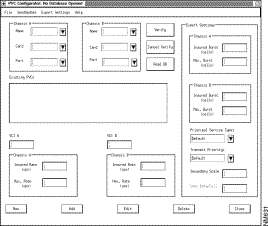
You can display expert mode settings in the PVC dialog box. To do so, click on the Expert Settings pull-down menu at the top of the screen and select Show. A screen like the one in Figure 3-37 is displayed. The appendix "Expert Mode" discusses expert mode fields and the options that they make available to you.
No expert mode settings are available for CEMAC circuits.
This section discusses virtual LAN internetworking (VLI), showing you how to set up the workgroups that are the basis for VLI configuration. In order to work with VLI configurations, you must configure at least one chassis and one Ethernet, FDDI, or fiber Ethernet card.
All interfaces in an LS2020 network belong to a default workgroup, which allows them to communicate with one another. Once you assign an interface to a workgroup that you define, however, that interface is removed from the default workgroup.
There are three main stages to setting up workgroups:
1. Creating the workgroup itself
2. Creating the lists of workgroup members
3. Assigning the members to the workgroup
These steps are discussed in the following paragraphs.
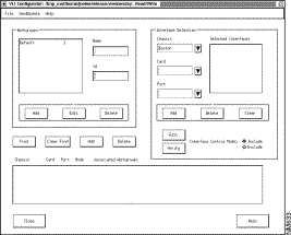
To create a VLI workgroup, use this procedure. The attributes used in this task are described in the following chapter in the section "VLI Attributes."
Step 2 Click in the Name field and enter a workgroup name.
Step 3 Click in the Id field and enter an ID. (Do not use 1, because that is the number for the default workgroup.)
Step 4 Click on the Add button. The workgroup name and ID are stored and displayed in the Workgroups list.
To change a workgroup name or ID, use this procedure:
Step 2 Click in the Name or Id field box (depending on which element you want to change), and make whatever change you wish.
Step 3 Click on the Edit button beneath the Workgroups list box. The workgroups list is modified according to the change you have made.
To delete a workgroup, use this procedure:
Step 2 Click on the Delete button beneath the list. The workgroup is deleted, and its name and ID are removed from the list.
To assign interfaces (ports) to a workgroup, use this procedure:
Step 2 Select an interface by specifying a chassis, card, and port. Use the list boxes in the Interface Selection portion of the screen.
Step 3 Click on the Add push button just below the list boxes in the Interface Selection section. The interface is listed in the Selected Interfaces box.
Step 4 Repeat Step 2 and Step 3 for each interface that you want to be a member of this workgroup.
Step 5 Click on the Add push button next to Clear Find (beneath the Workgroups listing). The button is just above the field box that lists associated workgroups. All entries from the Selected Interfaces list now appear in the Associated Workgroups list.
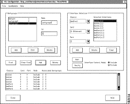
Step 6 Repeat Step 1 through Step 5 for each workgroup whose membership list you want to define. Figure 3-39 shows a VLI dialog box with members of two workgroups listed in the Associated Workgroups field box.
Even after the membership in a workgroup is defined, you can add members to or delete members from the group. First, though, you may want to check on group membership—confirm, that is, just which interfaces or ports belong to each group.
To determine the membership of a group, use this procedure:
Step 2 Click on the Find push button beneath the Workgroups box. A list in the Associated Workgroups box shows all interfaces in the workgroup that you have specified. It also shows any other workgroups that the various interfaces may belong to. At the same time, fields unrelated to your request for information are grayed out.
Step 3 When you have checked the membership list, click on the Clear Find push button. The screen is returned to its normal appearance.
To add one or more members to a group that has already been defined, use this procedure:
Step 2 In the Interface Selection block, press the Clear push button if any interfaces are listed there other than those you will want to add.
Step 3 Use the Chassis, Card, and Port list boxes to specify the interfaces that you want to add.
Step 4 When the list of interfaces is complete, click on the Add push button just above the Associated Workgroups box. The interfaces you have specified are added to the workgroup listings.
Step 5 Click on Save from the File pull-down menu to save the changes you have made.
To delete a member from a workgroup that has already been defined, you use one of two procedures, depending on whether the interface is in one workgroup (not counting the default workgroup) or more than one.
If the interface is in only the one workgroup, use this procedure:
Step 2 Click on the Delete push button just above the Associated Workgroups box. The interface is deleted from the list.
If the interface to be deleted is in more than one workgroup but you want to delete it from only one, use this procedure:
Step 2 Click on the Add push button in the Interface Selection box. The interface is listed under Selected Interfaces.
Step 3 In the Associated Workgroups list, click on the workgroup from which you want the interface to be removed.
Step 4 Click on the Delete push button that is above the Associated Workgroups list. The interface you have specified is removed from the selected workgroup.
After you add or delete an interface, select Save from the File pull-down menu to store the change you have made.
The default interface control mode is Include, and that is probably the choice you will use most often in defining workgroup membership. You can use Exclude, however, if you want a given interface (port) to be able to communicate with all but a few ports.
If you select a port and assign the Exclude control mode for one group, Exclude pertains to that port in any other workgroup to which it belongs. You cannot exclude an interface from some workgroups and include it in others. For example, if a port is a member of workgroups a, b, and c, you can change its control mode to Exclude for group b, but the same setting will then pertain for groups a and c.
To exclude an interface from a selected workgroup, use this procedure:
Step 2 In the Interface Selection block, specify the interface whose control mode you want to change. Use the Chassis, Card, and Port list boxes to specify the interface.
Step 3 Click on Exclude in the block for the interface control mode setting.
Step 4 Click on Edit in the Interface Selection block. The interface that you have specified now shows Exclude next to it in the Associated Workgroups list box. The Exclude setting pertains to all workgroups in the list for that interface.
Step 5 If you want this change to be permanent, select Save from the File pull-down menu,
Use the following procedure to exit from any of the configurators:
Step 2 Select Exit.
Step 3 If you select Exit without saving your changes first (see the following procedure), the configurator prompts you to save, discard, or cancel.
When the exit is complete, the configurator's dialog box closes.
Use the procedures described in the following paragraphs to save or abort changes made to a configuration database.
You can save changes periodically during your configuration session. To do so, pull down the File menu from the Node Configurator dialog box. Click on Save. Any changes made up to that point are saved to the global database.
Note Once you save changes, you cannot revert to the version of the database that existed before the save.
You can abort changes at the database level or at the dialog box level. At the database level, use this procedure:
Step 2 Click on discard if you do not want to save any changes.
Within a dialog box, if you want to negate the change you have just made, click on the Cancel button.
This section explains how to set update times for the configurator programs. Each configurator requires you to set update time attributes for each LS2020 node. (If you do not set these times, the nodes are not updated.) The update time attributes determine when the local databases will be updated and the type of update to be performed. Once you perform a save operation, the configurator updates the local databases at the times you have specified.
The update times for the different configurators need not coincide. The same switch can have different update times for its CFG, PVC, and VLI updates.
Note You may want to do a CFG update before a PVC/VLI update if the PVC/VLI values depend on node attribute values. Conversely, you should do PVC updates that involve PVC deletions before you do a CFG update if the node update involves deletion of cards with attached PVCs.
When an LS2020 switch is updated, the new configuration begins to take effect immediately, and the new data is completely distributed within a few minutes. If the update involves the reloading of an operating node, the flow of traffic may be briefly disrupted. (Only those ports or lines whose attributes are changed by the new configuration are affected.) If you are concerned about interrupting traffic, download configurations when the interruption will be least disruptive.
The following procedure is based on three assumptions:
Note If the update you are loading changes trunk parameters and if the update information is incompatible with the data it is replacing, update first the more distant nodes that have trunk parameter changes. (Distance here refers to the combined IP and LS2020 path from the NMS to the target node.) You will lose contact with those nodes until intermediate nodes receive the new parameters.
The CFG and VLI configurators have similar Update Time screens and similar update procedures, but the PVC configurator screens and procedures are different.
In order to schedule a CFG or VLI configuration update, use this procedure:
Step 2 Click on Update Time. The resulting dialog box displays the names of all chassis configured in the global database, as well as the update status and time for each chassis. (Figure 3-40 shows an example of this dialog box.)
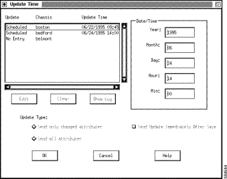
Step 3 Click on the name of the chassis that you want to update. You cannot select multiple chassis in this list.
Step 4 Select the type of update. Accept the default, which is to send only the changed attributes, or click on the Send all attributes radio button to select a full update.
Step 5 Select the date and time for the update. You have two options: (1) Click on Send Update Immediately After Save, or (2) select a year, day, and time for the update, using the field boxes and click on Edit. Clicking on Edit stores your changes so that they can be written to the global database. (The time is specified in 24-hour format.)
Step 6 Repeat the procedure in Step 3 through Step 5 for each chassis that you want to update.
Step 7 Click on the OK button to close the dialog box. After you save a configuration to the global database, the configurator updates each local database at the date and time you have specified.
The chassis list referred to in Step 3 includes (1) the status of the update at the time the dialog was displayed and (2) the timestamp of the currently configured update. The status is not updated while the dialog box is being displayed. Update status can be any one of the following:
Note If a chassis configuration is being updated and changes are made to a second chassis' configuration in the global database, those changes cannot be saved to the database while the download is in progress.
To enter an update time for a PVC pair, use this procedure:
Step 2 Click on UpdateTime. The resulting dialog box displays entries for chassis pairs whose update times are configured in the global database. The entry also gives the update status (in the column headed Update) and the update time. Figure 3-41 shows an example of the PVC Update Time dialog box.
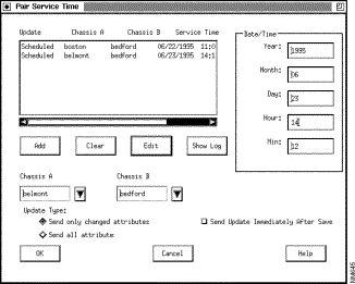
Step 3 Specify the chassis pair whose update time you want to set. Use the Chassis A and Chassis B list boxes to specify the two chassis.
Step 4 Select the type of update. Accept the default, which is to send only the changed attributes, or click on the Send all attributes radio button to select a full update.
Step 5 Select the date and time for the update. You have two options: (1) Click on Send Update Immediately After Save, or (2) select a year, day, and time, using the field boxes and click on Edit. (The time is specified in 24-hour format.)
Step 6 Repeat the procedure in Step 3 through Step 5 for each chassis pair that you want to update.
Step 7 Click on the OK button to close the dialog box. After you save the configuration to the global database, the configurator updates each local database at the time you have specified.
To change update time attributes for one pair, click on the desired entry in the list, make your changes, and click on the Edit button. The list is updated to show your changes.
Note Do not attempt to load PVC data during a CFG update. Before a PVC download, verify that both end ports are up and running and that the port types are correct.
To delete an entry, click on the desired entry in the list and click on the Clear button. The entry is removed from the list.
If you make changes to the update schedule, click on OK and then save the changes, so that the new values are entered in the global database.
This section tells you how to react to three error messages commonly encountered during an update. The error messages are recorded in the configurator's log files. See the following section for more information.
During the update, you may receive the following message:
If you receive this message, use Table 3-5 to determine the cause of the error. Reschedule the update after the problem has been corrected.
Table 3-5 Responding to Can't Get Lock on Chassis Error Message
During an update, you may receive the following message:
If you receive that message, use Table 3-6 to determine the cause of the error. Reschedule the update after the problem has been corrected.
Table 3-6 Responding to SNMP Timed Out Error Message
During an update, you may receive the following message:
If you receive that message, use Table 3-7 to determine the cause of the error. Reschedule the update after the problem has been corrected.
Table 3-7 Responding to No Such Item Error Message
The configurator creates a log file for each update of each switch. Use one of the following procedures to display the contents of a log file.
Use the following procedure to read log files from the CFG, PVC, or VLI configurator:
Step 2 In the Update Time dialog box, click on the chassis or chassis pair in the list box.
Step 3 Click on the Show Log button.
Step 4 Click on the desired log file from the list displayed in the pop-up dialog box.
Step 5 Click on the OK button in the pop-up dialog box; the contents of the file are displayed.
To display a different log file, click on the Another Log button and repeat Step 3 and Step 4. (If there are no other log files for the selected chassis or chassis pair, the button is grayed-out.)
To delete the log file, click on the Remove Log button. The file is deleted immediately.
To return to the dialog box, click on the Close button.
You can use a UNIX utility such as cat or more to display the contents of a log file. (Log files reside in a directory pointed to by LSC_LOGPATH variables.) See the appropriate UNIX documentation for information on using those utilities.
If you are running under HP OpenView, log files reside in the following path: /usr/OV/log. If you are running without HP OpenView, the log files reside in /usr/LightStream-2.1/log.
The configurator creates a subdirectory for each switch. The subdirectory is named with the switch's chassis ID. For example, log files for a switch that has chassis ID 5144 and that was created by a configurator running without HP OpenView are stored in /usr/LightStream-2.1/log/5144. PVC directory names consist of two node IDs with an underscore between them. The two IDs can be the same—for example, 5144_5144 is a valid name.
Log file names include the date, time, and configurator. See the following examples:
You can use a UNIX utility such as rm to delete a log file.
It is advisable to keep at least one up-to-date backup of your global configuration database on the NMS, disk space permitting. You should also make a copy of the global database on a tape or disk. See the documentation that came with your management station for information on how to copy to and restore from backup media.
Note If you need to restore a local database, simply update the switch from the global database. The procedure for doing so is described in the section entitled "Updating a Configuration " earlier in this chapter.
Use the procedure that follows to save a backup copy of your configuration database. Note that you can use either the Save As option or the Compress option in the File menu to accomplish this task. If you plan to put the backup file on tape, use Compress to ensure that the file will be small enough.
Note Backup files are meant to be used for archiving. They can be read and even changed, but they cannot be used to update a switch.
Step 2 Select either Compress or Save As. A dialog box like the one shown in Figure 3-42 is displayed.
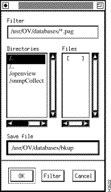
Step 3 Double-click in the Directories list to select a directory path. The path you select is shown in the Save File edit box.
Step 4 Click in the Save File edit box and enter a name for your backup copy. Use a name that is easily distinguished from the name for your operational copy.
Note After you enter a new file name in the Save file edit box, you may be asked to enter "an ordinary file name." This message is probably caused by your having entered a path for a file name that does not exist.
Step 5 Click on the OK button. The copy is written to the hard disk with the new name.
Note Actually two files are created—one with a .pag extension and one with a .dir extension. (If the file name you enter already ends in .pag, the name is not modified.) The .pag version is the only one that appears in the Files list, but the configurator uses both versions of the file.
To verify that the copy was created, you can pull down the File menu again and select Open. The pop-up menu that appears lists all database files that are present on the hard disk. Check that the backup file you just created is listed there. Click on the Cancel button.
In Step 3 above, there is a different way to specify a path name. You can also single-click in the Save File edit box and enter a file name. One problem with this approach, however, is that the cursor position is no longer visible. A "virtual cursor" exists at the point where the screen arrow was when you clicked the mouse button. As you start to type, new characters will appear, and from their position you will be able to tell where the cursor was and whether you placed it correctly.
You can also double-click in the Save File edit box at the point where you want to start entering a new file name. Doing so causes the path/file name already entered there to be highlighted in reverse video. The new path/file name that you enter then replaces the highlighted (existing) one.
Note You can use the Filter push button in combination with the Filter edit box to limit the display of file names to certain types. For example, suppose you enter a directory name in the Filter edit box followed by /*.pag and then click on the Filter push button. The only files displayed in the list box will be those in the directory you named that have a .pag file extension.
Use the procedure given here to open a configuration file. You can use this procedure to open a database file that is not specified by the LSC_DATABASE variable (for instance, a backup file).
Step 2 Select Open. A pop-up menu like the one shown in Figure 3-43 is displayed.
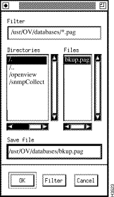
Step 3 In the Directories list on the menu, double-click on the correct path.
Step 4 In the File list, double-click on the name of the backup copy you wish to open.
Step 5 Click on the OK button. A pop-up dialog box is displayed.
Step 6 Select the database access mode. If you select read/write, the database is locked to other users and you can make changes to the database file. If you select read only, the file is not locked and you can only examine the settings in the file. If the configurator reports that someone else is using the database, you can override the configurator lock. (See the following section, "Overriding a Configurator Lock ," though, before proceeding.)
Changes you make during the configuration session are now saved to the file you have specified.
Note You cannot use a database unless it is specified by LSC_DATABASE to send the configuration to a chassis.
You can use the Filter button in the pop-up menu to search a directory for files with common strings in their names. For example, in the screen shown in Figure 3-43, the filter field shows as a default a search for files ending in .pag. To search for other files, you can click in the Filter field, change the search string, and then click on the Filter button to display files that correspond to the search string you have specified.
Do one of the following if you wish to use your backup files as your operational database files:
Use the following procedure to archive a backup copy of the database to a diskette:
Step 2 To compress the files, enter the following command at the system prompt:
Step 3 Insert a diskette into the disk drive attached to your workstation.
Step 4 Format the diskette by entering the following string:
You may need more than one diskette, depending on the size of the database.
Step 5 Once the floppy has been formatted, enter the following string:
If you are prompted for another diskette, remove the diskette from the drive and insert another one. If more than one diskette is required, number the diskettes in the order that you make them. When the copy is finished, remove the last diskette from the drive and number it. Store the diskette(s) in a safe place.
To recover the files from the floppy, use this procedure:
Step 2 Begin the recovery procedure by entering
If you are prompted for the next diskette, remove the diskette from the drive and insert the next one. When you have finished retrieving the files from diskette, remove the last diskette from the drive.
To uncompress the files, enter uncompress <filename>*.Z
If you want added backup protection, copy the backup database to another site. The configurator does not provide this function. Use the ftp command at the system prompt to transfer the .pag and .dir backup files to another site.
Each configurator provides a Verify function. Use the Verify function to
The Verify function retrieves information from the NP's run-time memory. The following sections discuss verification of CFG, PVC, and VLI attributes.
The Verify function does a node/global database comparison of parameters in eight groups:
1. Chassis level (for example, location, name, IP address)
To verify CFG attributes, use the following procedure:
Step 2 Click on the Verify button on the Node Configurator dialog box. All of the configuration settings are retrieved from the switch's run-time memory. The dialog box is updated to contain a summary of differences found between the global database and the switch database.
Step 3 Check the list to see the differences between the two databases.
| Caution If a card is down because of a fault or an administrative action, do not do an exhaustive card verify compare. Only the card type, slot number, and status are available to the Verify function. If you save the results of the Verify when a card is down, all of the other card and port attribute values in the configurator's temporary workspace are erased, and you will have to reconfigure them. If you accidentally save the results of the Verify (if you press Apply), you can either exit from the configurator without saving or you can wait until the card comes up and perform another Verify. (If you exit without saving, you lose any other changes you have made during the editing session.) |
Step 4 To store the settings from the local database in the configurator's temporary workspace, click on the Apply button. (This replaces any settings that were there.) If you don't want to incorporate the local settings, click on the Discard button.
Step 5 To save the settings from the local database in the global database, pull down the File menu and click on Save. Verifying more than eight nodes without saving can exceed the capacity of the switch's memory and result in failure of the save operation. It is therefore recommended that you save the global database after verifying eight nodes.
If you want to replace the local settings with the global settings, update the local database (see the section entitled "Updating a Configuration " earlier in this chapter).
You can retrieve configuration information for PVCs between switches, cards, or ports using the following procedure:
Step 2 Select the names of the chassis you want to verify in the Node A and Node B Name field boxes. You can refine your search further by selecting a card and/or port under the Node A and Node B field boxes.
Step 3 To retrieve configuration values from the switch, click on the Verify button. The configurator gets the current configuration from the local switch's run-time memory. It displays matching PVCs in the Existing PVCs list. Any differences between the global and local databases are displayed in a pop-up dialog box.
To retrieve the settings from the global database, click on Read DB. The Existing PVCs list is updated to show all PVCs currently configured between the specified endpoints in the global database.
| Caution If a card or port is down because of a fault or an administrative action, no PVCs are displayed. If you save the results of the Verify when a card or port is down, it erases all of the PVC attribute values for the selected endpoints in the global database. You must either reconfigure them or wait until the card/port comes up and perform another Verify. |
Step 4 To store the values from the local database in the global database, click on Save from the pop-up menu. The Verify function for the PVC configurator is different from that for the node and VLI configurators. It writes information from the switch directly to the global database, rather than to a temporary workspace. If you don't want to save the values, click on Cancel.
Verifying more than eight nodes without saving can exceed the capacity of the switch's memory and result in failure of the save operation. It is therefore recommended that you save the global database after verifying eight nodes.
Note Cancelling the verify operation discards all the PVCs read from the switch that appear in the list box and removes the pop-up menu from the screen.
To verify VLI attributes, use this procedure:
Step 2 Click on the interface that you want to verify in the Selected Interfaces list.
Step 3 To retrieve configuration values from the switch, click on the Verify button. The configurator gets the current configuration from the local switch's run-time memory and displays it in the Workgroups summary box.
| Caution If a card or port is down because of a fault or an administrative action, no workgroups are displayed. If you save the results of the Verify when a card is down, you erase all of the workgroup attribute values for that interface in the configurator's temporary workspace. You will have to reconfigure them. If you accidentally save the results of the Verify, you can exit from the configurator without saving or you can wait until the card/port comes up and perform another Verify. (If you exit without saving, you lose any other changes you made during the configuration session.) |
Step 4 To store the values from the switch in the configurator's temporary workspace, click on Save from the pop-up menu. This replaces any values that were in the temporary workspace with the information from the switch. (Click on Cancel if you do not wish to store the values.) Verifying more than eight nodes without saving can exceed the capacity of the switch's memory and result in failure of the save operation. It is therefore recommended that you save the global database after verifying eight nodes.
When the configuration database is locked, the database is in read-only mode. You should not edit it without investigating the reason for the lock. A database can become locked for either of two reasons:
When you open the database file, one of two messages is shown:
| Caution If another user is editing the database, do not override the lock or you will corrupt the database. Wait until the other user exits and the configurator automatically removes the lock, or use the database in read-only mode. |
There is one lock for the database, regardless of the tool used to access the database (Node Configure, PVC Configure, or VLI Configure). Use of any one of the configurators in read/write mode precludes the use of either of the others. For example, if someone is using the node configurator in read/write mode, the database is reported as locked if you try to open the file with PVC Configure or VLI Configure.
If you discover that the database is being edited simultaneously by two configuration tools, complete your edits with the second tool invoked, save, and exit. Then reopen the database with the remaining tool before editing.
![]()
![]()
![]()
![]()
![]()
![]()
![]()
![]()
Posted: Wed Jan 22 23:51:31 PST 2003
All contents are Copyright © 1992--2002 Cisco Systems, Inc. All rights reserved.
Important Notices and Privacy Statement.