|
|

This chapter provides troubleshooting information about connectivity and performance problems in the Layer 3 network connections of the switch router.
The chapter includes the following sections:
 |
Note For detailed cabling and hardware information for each port adapter, refer to the Catalyst 8540 CSR Route Processor and Interface Module Installation Guide. |
This section provides an overview of Layer 3 switching using the switch router. It shows how a switch router fits into the network, the architecture of the switch router, and the course of a Layer 2 and Layer 3 packet through the switch router. Also included is a list of Layer 3 switching software features with brief descriptions of selected features.
Layer 3 switching refers to a class of high-performance switch routers optimized for the campus LAN or intranet, providing both wirespeed Ethernet routing and switching services.
A Layer 3 switch router performs the following three major functions:
Compared to other routers, Layer 3 switch routers process more packets faster by using application-specific integrated circuit (ASIC) hardware instead of microprocessor-based engines. Layer 3 switch routers also improve network performance with two software functions—route processing and intelligent network services.
To simplify forwarding of the IP packets, route processing is usually executed during the initial call or session setup. At that point, the Layer 3 enabled ATM switch router determines the appropriate route, and forwards to the interfaces information describing the path to be used. In fact, data exchanged between the communicating source and destination end nodes may never need to flow to or through a conventional router.
Frame forwarding on subsequent packets in the same flow is performed using the Layer 3 switch functions at the line card. Once the route has been determined, all subsequent frames in the flow are simply switched or forwarded across the chosen path. This takes advantage of the high throughput and low latency characteristics of switching by enabling the traffic to bypass the route processor once a path calculation has been performed.
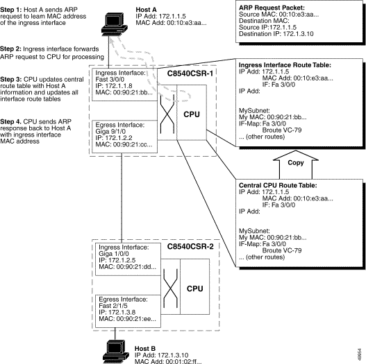
Figure 11-1 shows and describes, in Steps 1 through 4, how the initial packet travels through the switch Layer 3 route processor to set up the network route.
|
Note When making Layer 3 switching decisions, the route processor does not reference the switch fabric, (that is, the PVC configuration). The interface map (where the switch maps an egress interface to a Broute VC) is programmed when the switch is booted up. At that time, the PVCs are automatically configured. |
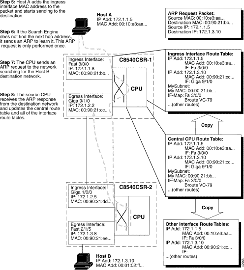
Figure 11-2 shows and describes, in Steps 5 through 7, how the route processor sends the ARP and propagates the updated routing tables to the interfaces.
|
Note In Figure 11-2, the ARP requests are described only for illustration purposes. In most cases, if you are running a dynamic protocol, the switches will have already sent and received ARP packets, and built the route tables. |
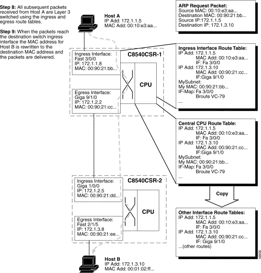
Figure 11-3 shows and describes, in Steps 8 and 9, how subsequent packets sent by Host A, to Host B, are switched without the help of the route processor.
By using CEF, each of the line cards maintains a Forwarding Information Base (FIB) table downloaded from the switch processor. Any changes made to the route processor routing table, caused by additions or deletions of routes or route flaps, are updated in the central FIB, which in turn updates the line card FIBs. This means that, at all times, all line cards have a correct map of the network topology.
Packet switching in the Layer 3 enabled ATM switch router takes place as follows:
Step 2 As soon as the first 64 bytes of the frame are read, the microcode running on the microcontroller reads the source and destination IP addresses, or IPX network information. If the destination MAC address belongs to the switch router, the packet is routed. If not, it is bridged.
Step 3 The destination IP address information is used by the search engine to begin a lookup, in the CAM table, for the longest match entry.
Step 4 The destination network is matched within 64 clocks (or approximately 2.5 microseconds). The match is returned to the microcontroller, which in turn moves the frame from the internal memory to the Fabric Interface frame FIFO buffer. At the same time, the search engine returns relevant information such as quality of service (QoS) classifications, and MAC header rewrite information, to the Control FIFO buffer.
Step 5 Packet rewrite and QoS classifications take place at the input Ethernet processor interface or Cisco Express Forwarding ASIC (CEFA).
Step 6 The VPI and VCI are attached at the beginning of the packet. The VPI and VCI used corresponds to the particular QoS being requested. The packet then goes through the SAR (Segmentation and Reassembly), which segments the packet into 48-byte payloads. The previously retrieved VPI and VCI-value is written into the cell header to complete the 53-byte ATM Cell.
Step 7 As soon as the entire frame is received into the Frame FIFO buffer, the frame moves into the shared fabric and is stored with a pointer to the output port.
Step 8 If that output interface is currently busy transmitting a frame, the scheduler uses WRR to determine which packet should be sent next.
Step 9 The destination port is signaled, by the switching-fabric ASIC, to take the frame out of a known memory location. The destination port knows that it is receiving the correct frame because of the internal routing tag corresponding to a particular, internal, port-to-port circuit.
Step 10 The frame is sent out to the network.
When a port or group of ports are running in bridging mode, the search engine initiates a lookup, in the CAM table, based on the Layer 2 MAC address. Because the Layer 3 enabled ATM switch router is a distributed switching system, each port (or in this case, CEFA) maintains a list of addresses and ports of exit that are of local significance. For example, if Address A is a destination learned on interface FastEthernet 0/0/1, the remaining interfaces on the switch do not have to have that address stored in their CAM tables unless they have a packet to send to Address A.
If the destination MAC address is a broadcast address (FFFF.FFFF.FFFF), the packet is tagged with the destination set as all ports in that bridge group, and it is sent out to the switching fabric. The fabric ASIC creates a pointer from that point in the memory to all ports in that bridge group. For example, if there were eight ports in a bridge group, all eight ports would receive that broadcast.
The following steps describe the MAC address learning process used by the switch router.
Step 2 The receiving port also sends a LightStream InterProcess Communication (LSIPC) message to the route processor to allow it to update the bridging table on the route processor.
|
Note This bridging table in the route processor is only used to allow you check the learned MAC addresses using the show bridge command. |
Step 3 All ports in the bridge group receive a copy of the "unknown unicast" and forward the packet.
Step 4 The receiving ports learn the new source address of the packet as a "remote entry."
Step 5 These receiving ports determine which interface sent the packet, based on the VPI and VCI header that points to a P2MP leaf, and the port already knows the corresponding P2MP root.
Step 6 Now all ports in the bridge port have learned the new source MAC address.
Step 7 The destination station for that frame responds.
Step 8 The port that receives the response learns the MAC address of the destination station (now the source address in the response). It has already learned the destination address, allowing it to forward the packet to the correct port.
Step 9 Only that egress port will then learn the new source address.
Step 10 The route processor is also notified of the new destination station source MAC address.
Step 11 Layer 2 switching then occurs between the two ports.
|
Note After 5 minutes of inactivity, MAC addresses are deleted from the CAM. The port sends another message to the route processor to remove the MAC from the bridging table. |
After both the source and the destination MAC address have been learned, the following procedure occurs during Layer 2 frame switching:
Step 2 As soon as the first 64 bytes of the frame are read, the microcode running on the microcontroller reads the MAC source and destination addresses. If the destination MAC address is not that of the interface, Layer 2 switching is required. This information can now be used by the search engine.
Step 3 Because the packet has been received on a particular VLAN, the search engine begins a search for the MAC address and its corresponding port of exit.
Step 4 The destination MAC address is found. The microcontroller moves the frame from the internal memory to the switching fabric. At the same time, the search engine returns relevant information such as QoS classifications or ISL information to the switching fabric.
Step 5 The VPI and VCI are attached at the beginning of the packet. The VPI and VCI that are used correspond to the particular quality of service being requested, the appropriate port of exit. The packet then goes through the SAR (Segmentation and Reassembly), which segments the packet into 48-byte payloads. The previously retrieved VPI and VCI values are written into the cell header to complete the 53-byte ATM Cell.
Step 6 The frame moves into the shared fabric and is stored sequentially.
Step 7 The destination port is signaled by the switching-fabric ASIC to take the frame out of memory. The destination port knows that it is receiving the correct frame because of the internal routing tag.
Step 8 The frame is re-encapsulated via ISL, if necessary, and sent out to the network.
The best way to understand the architecture of the Layer 3 enabled ATM switch router is to divide the switch into the following three distinct, functional segments:
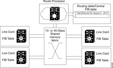
The switch route processor engine, show in Figure 11-4, is responsible for all address and route learning and distribution. Because the Layer 3 enabled ATM switch router is designed as a distributed switching system, the route processor (CPU) needs to ensure that all Layer 3 routes and Layer 2 MAC addresses are maintained and the line cards are updated as needed. The route processor is also responsible for handling all system management, including SNMP and remote monitoring (RMON) statistics.
The switching fabric or shared memory fabric, show in Figure 11-4, differs for the two Catalyst 8500 CSR switches. The Catalyst 8540 includes 12-MB shared memory while the Catalyst 8510 includes 3-MB of shared-memory. This shared memory is dynamic, meaning that a packet stored in memory takes only as much memory as it needs. Access into and out of the shared memory is dynamically allocated by the direct memory access (DMA) ASIC. Because the switch fabric is nonblocking, it does not require per-port buffers; the fabric speed is faster than the combined speed of all the ports. Congestion, therefore, only occurs when an individual output port is congested.
The line cards, show in Figure 11-4, are designed to carry considerable intelligence for the switching system. Each line card contains ASICs designed to provide input and output into the fabric as well as to maintain a Layer 3 FIB or a Layer 2 MAC address table. These tables allow the Layer 3 enabled ATM switch router to make switching decisions very quickly prior to transmission across the switching fabric. The line cards, therefore, must work closely with the route processor to ensure that all address tables and routing information is current. The line cards are also responsible for presenting a uniform frame to the switching fabric for effective buffering, QoS policy enforcement, and packet switching.
Each of the three main components of the Catalyst 8540 CSR are described in detail in the following sections.
The system route processor is the first element of the Layer 3 enabled ATM switch router architecture and resides at the core of the switch. The route processor resides on the switch route processor (SRP) module, along with the shared memory fabric, described in the "Switching Fabric and Arbitration" section. The route processor for the Catalyst 8510 CSR is a 64-bit 100Mhz R4600 RISC processor. Its architecture is very similar to that of the Cisco 7500 Route Switch Processor (RSP). The route processor for the Catalyst 8540 CSR is a 200Mhz R5000 RISC processor, very similar to the RSP-4 engine. The Layer 3 enabled ATM switch router SRP runs the Cisco IOS Release 12.0 or later software.
The route processor is responsible for running all of the routing protocols shown in Table 11-1<Xref_Color> on the Layer 3 enabled ATM switch router. Other protocols, such as AppleTalk, DECNet, and VINES are bridged in the switch.
|
Note The Catalyst 8540 CSR is designed to support multiprotocol routing. |
Most importantly, the route processor is responsible for maintaining the routing table. By using Cisco Express Forwarding, the route processor creates a FIB, which contains a subset of the routing table. The FIB is based on a topology map of the network, allowing routing to take place via the network topology at high speed. The FIB is then downloaded to the line cards, allowing the line cards to make Layer 3 routing decisions without having to interrupt the route processor. This capability allows the Layer 3 enabled ATM switch router to forward all frames at wire speed for all ports. The FIB and Cisco Express Forwarding are also described in the "Line Card Architecture" section.
The route processor is also responsible for maintaining state information regarding multicast routing. The Layer 3 enabled ATM switch router supports PIM (sparse mode and dense mode) as well as Distance Vector Multicast Routing Protocol (DVMRP) interoperability. The route processor is responsible for responding to and forwarding joins and leaves as well as responding to pruning messages sent by PIM. Multicast forwarding takes place at the line card level.
Although the switching decisions are made at the line cards, the route processor is still responsible for maintaining Layer 2 information. The route processor is responsible for bridge group configuration and spanning tree calculation.
Bridge groups are configured on the Layer 3 enabled ATM switch router in the same way they are in other Cisco routers. Instead of routing traffic to an outgoing interface, the traffic is bridged via its Layer 2 address. Integrated Routing and Bridging (IRB) is also supported in the Layer 3 enabled ATM switch router in order to support both bridging and routing at the same time.
Spanning tree information within the switch is maintained by the route processor. This includes calculation of the root bridge, optimum path determination to the root, and determining the forwarding and blocking links.
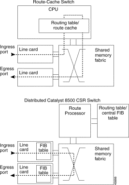
Cisco Express Forwarding (CEF) evolved to best accommodate the changing network dynamics and traffic characteristics resulting from increasing numbers of short-duration flows typically associated with Web-based applications and interactive multimedia sessions. Other Layer 3 switching paradigms use a route-cache model to maintain a fast lookup table for destination network prefixes (see Figure 11-5). The route-cache entries are traffic driven, in that the first packet to a new destination is routed via routing table information, and as part of that forwarding operation, a route-cache entry for that destination is added. This process allows subsequent packet flows to that same destination network to be switched based on a route-cache match. These entries are periodically aged out to keep the route cache current and can be immediately invalidated if the network topology changes.
This "demand-caching" scheme used by other Layer 3 switches is optimized for networks where the majority of traffic flows are associated with a subset of destinations. Since the traffic profiles at the core of the Internet (and potentially within some large enterprise networks) no longer resemble this model, CEF was introduced. CEF eliminates the increasing cache maintenance problem resulting from growing numbers of topologically dispersed destinations and dynamic network changes.
CEF avoids the potential overhead of continuous cache churn by using a FIB on the line card for the destination switching decision. The FIB mirrors the entire contents of the IP and IPX routing table. This means that there is a one-to-one correspondence between FIB table entries and routing table prefixes; therefore, a route cache does not need to be maintained.
|
Note Although CEF has been specified for IP, it also applies to IPX as well. |
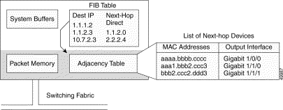
CEF provides features comparable to fast switching, including load sharing, recursive route resolution, and access lists. CEF uses two tables maintained in the SRP and downloaded to the line cards: the FIB and adjacency table. The FIB table is used for making forwarding decisions. The adjacency table maintains the adjacent nodes, and the link-layer information (such as packet rewrite information) necessary to reach that adjacent node. Every entry in the FIB table has a pointer to a corresponding entry in the adjacency table shown in Figure 11-6.
The FIB table is populated by callbacks (inputs) from the routing table. After a route is resolved, it points to a next hop, which should be an adjacency. This step is done at the SRP and then downloaded to the line cards, allowing the line cards to maintain a current topology of the network, which enables rapid switching decisions (within 10 ms) as well as fast convergence in the event of a routing topology change. The FIB is modified when a route is added, removed, or changed in the routing table. This information is immediately downloaded to the line cards.
The adjacency table is also populated by callbacks from the routing protocols, which include information such as next-hop information and (source, group [S,G]) interfaces for multicast groups. Adjacencies are added when a protocol detects that there is an adjacent node via the routing protocol. When a packet arrives at the ingress port, the CEF ASIC performs a FIB lookup based on the destination IP address. The matching FIB entry points to an adjacency entry, which in turn provides the valid link layer rewrite and outgoing interface. The packet is forwarded based on this information. Figure 11-6 shows the relation of the FIB to the adjacency table.
The Catalyst 8540 and Catalyst 8510 CSRs have different shared-memory architecture and system bandwidth. The Catalyst 8540 is based on a 12-MB shared-memory architecture with a total system bandwidth of 40 Gbps. The Catalyst 8510 is based on a 3-MB shared-memory architecture with a total system bandwidth of 10 Gbps. Both systems shared memory is completely nonblocking, meaning that all input ports have equal and full access into the shared memory for packet switching. The Layer 3 enabled ATM switch router also provides four queues per port, allowing the Frame Scheduler to make intelligent QoS decisions based on the priority of each queue.
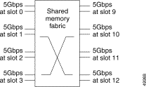
In the Catalyst 8540, each line card has 5-Gbps access into the shared memory fabric as shown in Figure 11-7. This bandwidth is also divided into 2.5 Gbps transmit and 2.5 Gbps receive paths into the fabric. This allows for nonblocking switching capacity within the switching system by ensuring that each line card is given more bandwidth than all of the ports on the line card can generate. Each of the line cards in the Catalyst 8510 is allotted 2.5 Gbps of capacity into the fabric. The 2.5-Gbps bandwidth is divided into transmit and receive paths, each of 1.25 Gbps, to ensure that both reads and writes to the shared memory can be accomplished simultaneously.
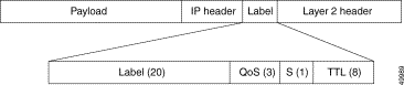
Because the Layer 3 enabled ATM switch router includes nonblocking memory, every port in the switch has full access to every other port. Each packet entering the switch fabric is tagged with an internal routing tag. This routing tag provides the switching fabric with the appropriate port of exit information, the QoS priority queue the packet is to be stored in, and the drop priority, shown in Figure 11-8.
The 4 byte routing tag contains a 20-bit label value, a 3-bit QoS value, a 1-bit stack indicator, and an 8-bit TTL value.
The Fabric-Switching ASIC (FSA) then queues each packet into memory and creates a pointer, based on the internal routing tag, to the appropriate destination port. The Frame Scheduler is then responsible for scheduling the frame out of memory based on the queue where the packet is being stored.
Each port transmitting through the fabric is, by default, placed in the lowest-priority queue. This places all traffic at a "best-effort" QoS level. When you configure a policy, that traffic is transmitted in the queue corresponding to the specified IP precedence. That queue is granted more service, thereby reducing latency and the possibility that traffic on that queue will be dropped.
|
Note All management and control plane traffic, such as BDPU information, routing protocol updates, and management frames are placed in the highest-priority queue for transmission to the route processor. |
The Frame Scheduler has two main responsibilities within the Layer 3 enabled ATM switch router: first, to schedule frames into the switching fabric based on the priority queue being requested, and second, to schedule frames out of the switching fabric based on the Weighted Round Robin (WRR) scheduling algorithm.
At the input to the switching fabric, the CEF ASIC posts a request to the Frame Scheduler for access to the fabric. The Frame Scheduler handles each request in a time-division multiplexing (TDM) fashion, meaning that each CEF ASIC will have the opportunity to clock an entire frame into the fabric when access has been granted. Because each CEF ASIC handles four ports, the Frame Scheduler allows the CEF ASIC to clock in a maximum of four packets into memory (see the "CEFA" section).
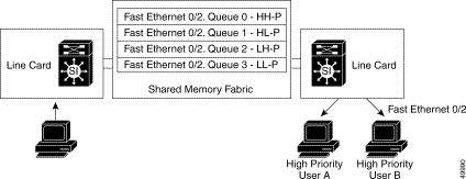
Each packet in memory has an internal routing tag added to the beginning which, as mentioned earlier, contains the port of exit, queuing priority, and drop priority. Based on the routing tag, the input Frame Scheduler places the packet in the correct queue (see Figure 11-9).
The "HH," "HL," "LH," and "LL" designations refer to the IP precedence fields used by the Layer 3 enabled ATM switch router to determine the appropriate queue.
|
Note Although not shown, a fifth, critical high-priority routing tag is added to the beginning of all management and control plane packets for immediate delivery to the route processor. |
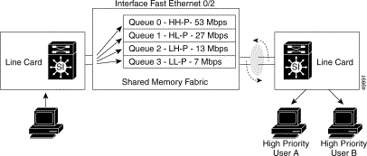
On the output side, the Frame Scheduler is responsible for servicing each queue based on the WRR priority scheme. WRR allows the network manager to configure how much service each queue receives. In a situation where there is no congestion, WRR and the weights provided do not play a real part on how packets are switched out of the fabric, because there is plenty of bandwidth available. However, if a link is congested, WRR services each queue per port based on the priority set by the network manager. For example, look at the weights assigned by a network manager in Table 11-1<Xref_Color>.
| Quality of Service Priority | Weight Given by Network Manager | Bandwidth Assignment Calculation | Bandwidth Assigned |
|---|---|---|---|
Based on the priorities and weights provided, the Frame Scheduler services QoS-0 more often, granting queue 53 Mbps out of the 100 Mbps possible on the output link. The second queue, QoS-1, receives 27 Mbps of the bandwidth, and so forth. These commands are set globally on the switch router and function the same for all ports on the switch.
The switch router also allows you to override the global QoS settings by allowing port-to-port communications to have a different level of priority. You have the option of configuring bandwidth based on a source-destination, destination, or source basis and provide weights based on certain IP addresses having more bandwidth then others.
|
Note This feature is available with the hardware access list daughter card installed on an Ethernet interface module installed in the Catalyst 8510 CSR. |
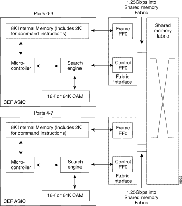
The last major component of the Layer 3 enabled ATM switch router architecture is the line cards. Because the switch uses a distributed architecture, the line cards must be intelligent enough to make both Layer 3 and Layer 2 forwarding decisions at wire speed for all media types, as well as enforce QoS policies. Figure 11-11 details the architecture of the Layer 3 enabled ATM switch router line cards. In Figure 11-11, notice that the Catalyst 8540 uses four CEFAs per line card.
The Layer 3 enabled ATM switch router line cards are based on the Cisco Express Forwarding ASIC (CEFA). The CEF ASIC is based on the MMC Ethernet processor interface ASIC. It is called the CEF ASIC since the Cisco Express Forwarding mechanism is programmed into the ASICs. This ASIC is responsible for the Ethernet MAC layer functions, address or network lookup in the content-addressable memory (CAM) table, and forwarding of the packet with its correct rewrite information to the Fabric Interface. The Fabric Interface is also resident on the line card and is responsible for the packet rewrite, QoS classification, and signalling to the Frame Scheduler.
The CEFA is at the heart of the line card architecture. This ASIC has several key components that will be discussed in detail. Each CEFA services four ports on the line card. In order to service eight ports, two CEFAs are used per line card. On the Catalyst 8540, four CEFAs are used in order to service 16 ports. Although not shown in Figure 11-11, the CEFA is responsible for all MAC layer functions. The MAC is 10/100 autosensing and autonegotiating, if so configured. The MAC can also be run in either full or half duplex mode.
Packets entering the switch port and having passed though MAC functions are stored in an internal block of SRAM. This memory is 8 kilobytes in size, with 2K reserved for command instructions. This memory is used to hold the packet while the appropriate lookups take place.
The CEFA microcontroller is a mini-route processor that is local to four ports on the Layer 3 enabled ATM switch router line module. The microcontroller is designed to handle the traffic on each of the ports in a fair manner. This means the CEFA must ensure that all packets have equal access into internal memory and that lookups via the search engine are done fairly by arbitrating service between the four ports. This is handled in a round-robin manner, meaning that the microcontroller cycles between each port, processing requests as needed.
The microprocessor also has the critically important task of forwarding system messages such as spanning tree BPDUs, routing advertisements, Cisco Discovery Protocol (CDP) packets, Address Resolution Protocol (ARP) frames, and other control-type messages back to the route processor. Those messages are forwarded by the CEFA to the route processor.
The search engine in the CEFA performs the address lookup or network output interface lookup. It performs its lookup in the CAM table, which can hold either 16,000 or an optional 64,000 entries. The search engine can make two types of switching decisions: Layer 2 based or Layer 3 based. With the hardware-based access list feature card, the search engine can also perform lookups based on Layer 4 information. The search engine is therefore responsible for maintaining the Layer 2 MAC address table and the Layer 3 FIB.
An incoming packet is placed into the internal memory. As soon as the first 64 bytes of the frame are read into memory, the microcode signals the search engine with the relevant source or destination MAC address, destination network, or Layer 4 port information. The search engine can then conduct a lookup in the CAM table for the corresponding entry. Using a binary tree lookup method, the search engine can hit a MAC address or perform a longest match on the destination network address very quickly. The corresponding rewrite information, which is stored in the CAM table, is then delivered to the control FIFO buffer of the Fabric Interface.
The final stage in packet switching within the Layer 3 enabled ATM switch router can now occur. The switching CEFA now knows the port-of-exit for the packet based either on its MAC address or on the Layer 3 IP or IPX network numbers. The packet must now be transferred across the switching fabric to the destination. The Fabric Interface is responsible for preparing the packet for its journey across the switching fabric.
The Fabric Interface consists of two main components: the frame FIFO buffer and the control FIFO buffer. Figure 11-11 shows the internal memory of the CEFA, its direct connection into the frame FIFO buffer, and the direct connection from the search engine into the control FIFO buffer. When the search engine completes the lookup, the packet moves from internal memory into the frame FIFO buffer. In parallel, the search engine returns to the control FIFO buffer all of the relevant rewrite and QoS information.
The Fabric Interface then rewrites the packet with the appropriate information and calculates the checksum. At the same time, the Fabric Interface adds to the beginning of the packet the internal routing tag containing port of exit, the QoS priority, and drop priority (see Figure 11-8). Once completed, the Frame Scheduler is signaled to place the frame into the fabric.
At the output port, the Fabric Interface forwards the packet to its output MAC. Since all rewrite and error checking has been done at the ingress port, no additional work needs to be performed on that frame.
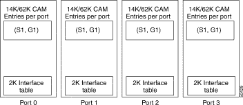
Private CAM describes where each interface has its own CAM. The CAM space is used to store direct lookup tables, Layer 2 and Layer 3 forwarding tables that assist in the ASIC hardware forwarding. See Figure 11-12.
The various CAM types are described as follows:
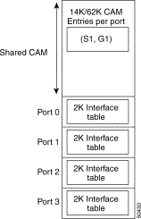
The shared CAM allows one single CAM space per Ethernet processor interface, and this CAM space is physically shared among all four ports within this interface. See Figure 11-13. Shared CAM space has implications in the way the direct lookup table and Layer 3 database are maintained in the CAM.
|
Note A shared CAM board and non-shared CAM board can co-exist in the same switch router. |
There are always five P2MP VCs in the switch router:
With shared CAM, Gigabit processor interface P2MP remains the same. However, for Ethernet processor interfaces with shared CAM, only channel-0 leaf is created. Other channel leaves are not created. This allows a mix of private, shared, and dual CAM interfaces in the switch router.
To determine what type of CAM is installed on your interface use the show hardware detail command as shown in the following example:
In the previous example, the CAM Type field lists the CAM type for the ARM module in slot 2/* as Dual and the CAM type for the Ethernet module in slot 3/* as Private.
Data plane traffic is traffic between two endpoints (for example, a host on subnet A communicating with a host on subnet B). This data plane traffic will be typically switched by the Ethernet processor interface or Gigabit processor interface. Control Plane traffic is traffic which is handled by the route processor, typically Layer 2 and Layer 3 protocol updates.
The following is a list of traffic considered to be Control Plane traffic and handled by the route processor:
IP packets are sent to the route processor in the following situations:
IPX packets are sent to the route processor in the following situations:
The following packets are sent to the route processor on the control plane:
Autonegotiation converges to using the minimum capability of the local interface and the peer interface. For example, if the local interface is capable of full-duplex transmission and the peer interface is only capable of half-duplex transmission, after the local interface performs autonegotiation the interface changes to operate in half-duplex mode.
If the peer interface does not have transmission mode autonegotiation capability, but the local interface has transmission mode autonegotiation capability and the local interface receives no response to its negotiation requests, the local interface changes to operate in half-duplex mode.
To Support half-duplex and full-duplex autonegotiation, your interface must confirm to the following:
Other interfaces (10/100Mbps Ethernet processor interface versions less than C1) have a default speed of 100Mbps, full duplex, and are not capable of autonegotiation.
To determine the installed interface version, use the show controllers {fastethernet | gigabitethernet} slot/subslot/port command and find the EVER field under the Slicer registers. The Ever field should be EVER 0x1704 (C1); or if it is not, your interface is not capable of autonegotiation.
To troubleshoot half- and full-duplex negotiation problem, use the following commands:
| Command | Purpose |
|---|---|
show interfaces {fastethernet | gigabitethernet} slot/subslot/port |
|
show controllers {fastethernet | gigabitethernet} slot/subslot/port |
Follow these steps to troubleshoot the half- and full-duplex negotiation problem on an interface:
Step 2 Check the Auto-duplex, Auto Speed, 100BaseTX fields. They should have the following default configuration:
If they do not, check the peer interface and determine whether it is capable of this configuration.
Step 3 Use the show controllers fastEthernet card/subcard/port command to check the half-duplex and full-duplex autonegotiation configuration.
|
Note The show controllers command for a specific interface has different information depending on the IOS software version running on your Layer 3 enabled ATM switch router. |
Step 4 Use the show controllers fastEthernet card/subcard/port command to check the configuration. The following example uses the Cisco IOS Release 12.0(5)W5(13b) and later display:
Use the show controllers fastEthernet card/subcard/port command to check the configuration. The following example uses the Cisco IOS Release 12.0(5)W5(13) and earlier display:
Step 5 Check the Auto Neg. Advertisement Register (Reg 0x4). If it is set to 1, the following are the capabilities:
Step 6 Check the Auto Neg. Partner Ability Reg (Reg 0x5). If it is set to 1, the following are the status and capabilities:
Step 7 Check the Chip Status Register field. It should match the link status, duplex mode, and speed shown in the show interface command in Step 2.
The Layer 3 enabled ATM switch router uses Cisco Express Forwarding (CEF). Much of the internal troubleshooting determines whether the central CEF information in the route processor is consistent with the distributed information in the content addressable memory (CAM) on the interfaces.
Troubleshooting an IP Layer 3 connection is separated into the following processes:
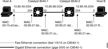
Figure 11-14 shows the example network used to troubleshoot an IP Layer 3 connection in the following examples.
In Figure 11-14, Host A is the source end station trying to communicate with Host B, the destination end station.
To troubleshoot an IP Layer 3 connection problem, use the following commands:
Follow these steps to verify the IP routing tables in the IP Layer 3 connection shown in Figure 11-15.
|
Note All the networks are directly connected except for 10.85.45.0, which was learned through EIGRP, via interface Gigabit Ethernet 0/0/0. |
Step 2 From the Catalyst 8540-1, use the show ip route command to display the network connecting Host B to Catalyst 8540-2 with IP address 10.85.45.0.
The display confirms the route to network 10.85.45.0, which exists in the routing table and was learned via IP address 10.85.66.5 through Gigabit Ethernet interface 0/0/0.
|
Note If there are routes missing, continue with normal IP routing troubleshooting for the routing protocol you are using. |
If you determine that the interface is configured incorrectly, refer to the "Configuring Interfaces" chapter in the Layer 3 Switching Software Feature and Configuration Guide .
Follow these steps to verify the interface status in the IP Layer 3 connection shown in Figure 11-16.
Step 2 From the Catalyst 8540-1, use the show controllers c8500 status command to display the status of the interfaces used in this example.
The OK in the show controllers c8500 status command display indicates the microcode was successfully downloaded to the Fast Ethernet processor interface and Gigabit processor interface.
Step 3 From the Catalyst 8540-1, use the show controllers c8500 counters command to display the status of the interfaces and the Input and Output Packet numbers.
Step 4 Check the Interface State field. It should indicate the interfaces are up.
Step 5 Check the Input Packets and Output Packets fields. The show controllers c8500 counters command should be entered at least twice. The counters in the Input Packets and Output Packets fields should be incrementing. This information can also be displayed using the show interfaces command.
|
Note The clear counters command does not clear the show controllers c8500 counters command display. |
If you determine that the interface is configured incorrectly, refer to the "Configuring Interfaces" chapter in the Layer 3 Switching Software Feature and Configuration Guide .
Follow these steps to verify the IP CEF adjacencies in the IP Layer 3 connection shown in Figure 11-17.
The information in the show ip cef command display is built from the IP routing table and resides on the route processor.
The following is an explanation of the information in the Next Hop Column:
Step 2 From the Catalyst 8540-1, use the show ip cef command with the destination network IP address to display the CEF FIB table entry for the network connecting Host B to Catalyst 8540-2 with IP address 10.85.45.0.
The display confirms that the next hop IP address 10.85.66.5 is valid and has a valid cached adjacency.
Step 3 From the Catalyst 8540-1, use the show adjacency command to display the MAC address rewrite information for the connection from Catalyst 8540-1 to Catalyst 8540-2 with IP address 10.85.66.5.
The display confirms the MAC address rewrite information as:
If the next hop interface does not display the correct MAC address rewrite information, use the show arp command to confirm the MAC addresses.
Step 4 From the Catalyst 8540-1, use the show arp command to display the ARP table.
The first entries in this ARP table are, from top to bottom:
If you confirm the information is wrong using the show adjacency command to display the MAC address rewrite information, this might indicate a problem with CEF. You should confirm the interface CAM table entries using the following troubleshooting procedure.
If you determine that the interface is configured incorrectly, refer to the "Configuring Interfaces" chapter in the Layer 3 Switching Software Feature and Configuration Guide .
Follow these steps to verify the interface CAM table entries in the IP Layer 3 connection shown in Figure 11-18.
The Prefix/Masklen indicates the IP addresses and subnet masks of connections in the interface CAM table.
The Not configured field indicates no default route is known. If you added IP route 0.0.0.0 20.0.0.1 to that configuration, the display would change to include the following:
|
Note Since there is only one route, the Load Balancing field is Off. |
The next hop column contains the following descriptions:
All interfaces should have the same CAM entries, since the forwarding decision is made based on the information contained in the CAM table. This table is based on the network topology, not traffic flows. The show epc ip-prefix command used with any other interface on the switch should contain the same number of entries in the Total IP Prefix Entries in the CAM field (in this example, 25).
Additionally, you can use other show epc ip-prefix interface command parameters to check the cam-summary as well as the fail-entries and fail-summary.
Step 2 From the Catalyst 8540-1, use the show epc ip-prefix interface command to display the connection ingress interface to IP address 10.85.45.0.
The Gateway IP address should match the next hop IP address in the show epc cef command output in Step 2 in the section "Checking the IP CEF Adjacencies" section.
To remove inconsistencies between the CEF table and the IP prefix table, use the clear ip route command to rebuild these tables. You can either clear a specific route or use an asterisk (*) to clear all routes.
 |
Caution Use the clear ip route command carefully. It causes a temporary increase in switch router activity which can lead to traffic disruptions. |
Step 3 From the Catalyst 8540-1, use the show epc ip-address command with the IP address of the egress interface to display the status of the MAC address rewrite.
The information in this display should match the information shown using the show adjacency command to display the MAC address rewrite in Step 3 of the "Checking the IP CEF Adjacencies" section.
The display confirms the MAC address rewrite information as 0090.21dd.dddd, the Catalyst 8540-2 destination MAC address, and provides the interface index number, in this example "(4)", to use in the command in Step 5.
Step 4 From the Catalyst 8540-1, use the show epc lsipc command to display the status of the interprocess information between the route processor and the Ethernet processor interfaces and Gigabit processor interfaces.
Check the Bcast fields for any failures. If messages are getting dropped, that could cause inconsistencies in the routing table transfers between the route processor and Ethernet processor interfaces and Gigabit processor interfaces. For example, the IPC communications could have failed.
Step 5 From the Catalyst 8540-1, use the show epc ifmapping command to display the status of the interface mapping of the egress interface.
The IF number field, in this example "(4)", indicates the interface index number is mapping correctly.
Step 6 From the Catalyst 8540-1, use the show epc patricia interface command with the ipucast detail parameters on the ingress interface to display the status of the Host Entry CAM location for the connection to Host B.
The Mac Addr field in the command display indicates the correct MAC address for IP address 10.85.66.5, the next hop, is at the CAM entry location with hexadecimal address 0x102D.
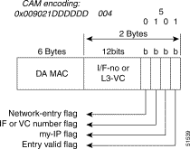
Step 7 From the Catalyst 8540-1, use the show epc cam interface command with the CAM location hexadecimal address 0x102D and the CAM word 2 parameters to display the status of the MAC rewrite for this interface.
Figure 11-19 describes the CAM encoding information shown in the show epc cam interface command, using the CAM location hexadecimal address 0x102D and the CAM word 2 parameters.
The Data fields in the display indicate the MAC address is written to the following:
|
Note The interface or VC number flag indicates the 12 bits are interpreted as either an interface
or ATM VC number. If this were an ATM router module, you could configure the VC to
transmit on the ATM side. The VC is then one of the following: — a data direct VC for ATM LANE — a PVC or SVC for 1483 or 1577, respectively |
Step 8 If this process has not resolved the IP Layer 3 connection failure, repeat this same process for the reverse path from the destination host, and verify that all other interfaces have similar CAM table entries.
|
Caution Be aware that asymmetrical routing could lead to multicast delivery on an alternate, unintended path, if a forwarding algorithm based on Reverse Path Forwarding is used. |
Step 9 From the Catalyst 8540-1, use the show epc if-entry interface command with the entry interface parameters to display the status of the Broute VC.
For inconsistencies between the adjacency table and the EPC IP address table, use the clear arp or clear adjacencies commands to rebuild the table. When you use one of these commands, the switch router sends an ARP request for all entries in the ARP cache. As replies come back, it will refresh the cache. If any entries time out, they will be cleared from the table. The switch router will then build the adjacency table using this information, and then populate the interface EPC IP address table.
If you find inconsistencies between the IP route table, CEF table, and the epc ip-prefix table, the clear ip route command will rebuild the entries in these tables. You can either clear a specific route using the clear ip route ip-address command or use the clear ip route * command to clear all routes. The routing protocol should relearn the routes and then rebuild the CEF table. The switch router then passes this information to the interfaces and into the ip-prefix tables.
|
Caution There will be a momentary spike in route processor activity and a corresponding traffic disruption. Use caution when performing the previously described workarounds in a production network. |
If you determine that the interface is configured incorrectly, refer to the "Configuring Interfaces" chapter in the Layer 3 Switching Software Feature and Configuration Guide .
Similar to troubleshooting IP Layer 3 routing connections, the key to troubleshooting IPX Layer 3 routing is to check on consistency between information contained in the route processor and what is in the CAM tables on the ports.
Troubleshooting an IPX Layer 3 connection is separated into the following processes:
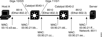
Figure 11-20 shows the example network used to troubleshoot an IPX Layer 3 connection in the subsequent examples.
In Figure 11-20, Host A is the source end station trying to communicate with the Novell Server that is part of IPX network 8511, the destination end station.
IPX troubleshooting is similar to IP troubleshooting. The key is to check the consistency between the route processor table information and CAM tables on the ports.
To troubleshoot IPX Layer 3 connection problems, use the following commands:
Follow these steps to verify the IPX routing tables in the IP Layer 3 connection shown in Figure 11-21.
Step 2 Check the Connected primary network (indicated with a "C"). The Novell network numbers 8511 and 8512 should appear as connected through interface Gigabit Ethernet 11/0/1.
Step 3 From the Catalyst 8540-1, use the show ipx servers command to verify the connection to the server in Novell network 8511, in the example network shown in Figure 11-21.
Step 4 Confirm that the network (Net) number 8511 appears in the Periodic (indicated with a "P") row of the connection list.
|
Note SAP entries reside in route processor Memory, not on the CAM tables. |
Follow these steps to check the IPX CEF adjacencies in the IPX Layer 3 connection shown in Figure 11-22.
Step 2 Confirm the following:
Step 3 This interface CAM information should match the information shown in Step 1 of the "Checking the IPX Routing Table" section.
Step 4 Use the show ipx cef command with the source network number (8541), netmask, and interface parameters to display the status of the CAM table on the egress interface.
Step 5 Confirm the same parameters as in Step 3.
Step 6 From the Catalyst 8540-1, use the show epc ipx-node command with the IPX network and node addresses to display the status of the IPX network to node mapping.
Step 7 From the Catalyst 8540-1, use the show epc ifmapping command to display the IF number mapped to the egress interface GigabitEthernet 11/0/1.
The IF number field (in this example "39") is used in Step 9.
Step 8 From the Catalyst 8540-1, use the show epc patricia interface command with the ipx detail parameters on the egress interface to display the status of the Host Entry CAM location for the connection to Host B.
Look at entry 2#. The word "dirty" in the display is a normal entry type. The prefix (IPX network number) and node numbers are displayed. The entry marked "My-Node Valid" is for the directly connected interface on Catalyst 8540-1. The other node entry, marked Valid, is for host A on the network. Make a note of the hexadecimal address 0x101B (converted to decimal 4123). You need that hexadecimal address, converted to decimal 4123, in Step 9.
Entries 3 and 4 are remote entries. NHOP1 means these are pointers to the adjacency entry for the next hop to get to the IPX networks Prefix 0x8512 and Prefix 0x8511. These are not the MAC addresses of the next hop. Valid means the entry is valid and usable.
Step 9 From the Catalyst 8540-1, use the show epc cam interface command with the CAM location hexadecimal address 0x101B (converted to decimal 4123) and the CAM word 2 parameters to display the status of the MAC rewrite for this interface.
The ingress interface fields in the display indicate the MAC address is written to the following:
Step 10 From the Catalyst 8540-1, use the show epc if-entry interface command with the entry interface parameters to display the status of the Broute VC.
Step 11 Check the following:
If you have any problems with these fields, check the interface configuration. For information about configuring interfaces, refer to the Layer 3 Software Feature and Configuration Guide.
IP multicast allows IP traffic to be sent from one source or multiple sources and delivered to multiple destinations. Instead of sending individual packets to each destination, which is highly taxing to the switch fabric, a single packet is sent to a multicast group, which is identified by a single IP destination group address. That IP destination group consists of a number of IP destinations that require that frame. From a router perspective, an input multicast feed from a given source must be sent out through (possibly) multiple output interfaces based on the information received by the multicast routing protocols such as PIM.
The Layer 3 enabled ATM switch router supports IP multicast at wire speed for all ports, allowing for high-speed switching of packets from input source ports to multiple destination ports. The Layer 3 enabled ATM switch router also supports IP multicast routing protocols such as PIM dense and sparse modes, as well as DVMRP interoperability.
The Internet Group Management Protocol (IGMP) provides a method for end stations to request multicast traffic as well as for switch router to determine who on a locally attached segment is requesting traffic. IGMP uses IP datagrams to allow IP multicast applications to join a multicast group. IGMP relies on Class D IP addresses for the creation of multicast groups and is defined in RFC 1112. Membership in a multicast group is dynamic, meaning that it changes over time as hosts join and leave the group. Multicast switch routers use IGMP host-query messages (sent to the group address 224.0.0.1 with a TTL of 1) to keep track of the hosts that belong to multicast groups. When switch router receives a packet addressed to a multicast group, it forwards the packet to those interfaces that have hosts belonging to that group. Switch routers periodically send host-query messages to refresh their multicast group membership knowledge.
The Catalyst 8500 supports both IGMP version 1, which most end stations currently support, and IGMP version 2, which, unlike version 1, provides support for clients informing the network that they are leaving a multicast group.
As networks increase in size, multicast routing becomes critically important in order to determine, in a large routed network, which segments require multicast traffic and which do not. PIM is a routing protocol for multicast that uses existing unicast routing protocols such as RIP or OSPF for path forwarding determination and network location. PIM can be operated in two modes. PIM dense mode and PIM sparse mode. The mode selected determines how the switch router populates its multicast routing table, and how the it forwards multicast packets it receives from its directly connected LANs.
|
Note Enabling PIM on an interface also enables IGMP operation on that interface. |
In dense mode, a switch router assumes that all other switch routers want to forward multicast packets for a group. Therefore, interfaces with PIM dense mode enabled receive the multicast feed as soon as a single user requests one. That segment will continue to receive the multicast until it times out. If a Catalyst 8500 receives a multicast packet and has no directly attached members or PIM neighbors present, a prune message is sent back to the source. Subsequent multicast packets are not flooded to this pruned branch. PIM builds source-based multicast distribution trees. PIM dense mode is most useful when:
In sparse mode, a switch router assumes that other switch routers do not want to forward multicast packets for a group, unless there is an explicit request for the traffic. When hosts join a multicast group, the directly connected switch routers send PIM join messages to the rendezvous point (RP). The RP keeps track of multicast groups. Hosts that send multicast packets are registered with the RP by that host's first-hop switch router. The RP then send joins toward the source. At this point, packets are forwarded on a shared distribution tree. When the data stream begins to flow from sender to RP to receiver, the switch routers in the path optimize the path, automatically, to remove any unnecessary hops. Sparse mode assumes that no hosts want the multicast traffic unless they specifically ask for it.
Sparse mode PIM is optimized for environments where there are many multipoint data streams and each multicast stream goes to a relatively small number of LANs in the internetwork. PIM sparse mode is most useful when:
There are two types of rendezvous points: statically configured and Auto-RP.
A statically configured PIM rendezvous point (RP) address is used by first-hop switch routers to send Register packets on behalf of source multicast hosts. The RP address is also used by switch routers on behalf of multicast hosts that want to become members of a group. These switch routers send Join and Prune messages toward the RP. A single RP can be configured for all multicast groups or a subset of the Class D address range as described by the access-list pointer.
Auto-RP automates the distribution of group-to-RP mappings in a PIM network. This feature has the following benefits:
Multiple RPs can be used to serve different group ranges or serve as hot backups of each other. To make Auto RP work, a Layer 3 enabled ATM switch router must be designated as an RP-mapping agent, which receives the RP-announcement messages from the RPs and arbitrates conflicts. The RP-mapping agent then sends the consistent group-to-RP mappings to all other switch routers. Thus, all switch routers automatically discover which RP to use for the groups they support.
One way to start is to place (preserve) the default route processor for all global groups at or near the border of your routing domain, while placing another route processor in a more centrally located switch router for all local groups using the administratively scoped addresses (239.x.x.x).
|
Note If you configure PIM in sparse mode or sparse-dense mode and do not configure Auto-RP, you must statically configure an RP. |
DVMRP is the first-generation multicast routing protocol most known for its use in the Multicast Backbone (MBONE). DVMRP uses a flood-and-prune approach to multicast packet delivery. This means that DVMRP assumes that all other switch routers in a network want to forward multicast packets for a group. This creates huge scalability problems, as switch routers must now maintain state for multicast paths that may not require or want to handle multicast traffic. For that reason, the Cisco switch router does not support DVMRP, but does support DVMRP interoperability with PIM. This allows the Cisco switch router to interoperate with non-Cisco multicast switch routers that use DVMRP.
Cisco IOS software in the Catalyst 8500 supports dynamic discovery of DVMRP switch routers, and can interoperate with them over traditional media or over DVMRP-specific tunnels. When a DVMRP neighbor has been discovered, the switch router periodically transmits DVMRP report messages advertising the unicast sources reachable in the PIM domain.
When a Cisco switch router runs DVMRP over a tunnel, it advertises sources in DVMRP Report messages much as it does on real networks. In addition, the software caches DVMRP Report messages it receives and uses them in its Reverse Path Forwarding (RPF) calculation. This allows the software to forward multicast packets received over the tunnel.
Essential to multicast routing is the idea of spanning trees. Multicast routing procedures, for example PIM, construct these trees (with receivers as leafs), while multicast forwarding forwards multicast packets a long the trees.
To support a multicast forwarding function with tag switching, each tag switch associates a tag with a multicast tree as follows. When a tag switch creates a multicast forwarding entry (either for a shared or for a source-specific tree), and the list of outgoing interfaces for the entry, the switch also creates local tags (one per outgoing interface). The switch creates an entry in its TIB and populates (outgoing tag, outgoing interface, outgoing MAC header) with this information for each outgoing interface, placing a locally generated tag in the outgoing tag field. This creates a binding between a multicast tree and the tags. The switch then advertises over each outgoing interface associated with the entry the binding between the tag (associated with this interface) and the tree.
When a tag switch receives a binding between a multicast tree and a tag from another tag switch, if the other switch is the upstream neighbor (with respect to the multicast tree), the local switch places the tag carried in the binding into the incoming tag component of the TIB entry associated with the tree. When a set of tag switches are interconnected via a multiple-access subnetwork, the tag allocation procedure for multicast has to be coordinated among the switches. In all other cases tag allocation procedure for multicast could be the same as for tags used with destination-based routing.
Cisco Group Membership Protocol (CGMP) addresses the issue of efficiently forwarding IP multicast packets across Layer 2 switches. CGMP allows Layer 2 switches to leverage IGMP information recorded on the Catalyst 8500 to make intelligent Layer 2 forwarding decisions based on the destinations requesting the multicast traffic. The net result is that with CGMP, IP multicast traffic is delivered only to those Layer 2 switch ports that are interested in multicast traffic. All Layer 2 switch ports that have not requested the traffic do not receive it. When a Layer 3 enabled ATM switch router receives an IGMP join message, it records the source MAC address of the IGMP message, and turns around and issues a CGMP join message downstream, to a Layer 2 switch. The switch uses the CGMP message to dynamically build an entry in the switching table that maps the multicast traffic to the client switch port.
The Catalyst 8500 uses PIM, not CGMP, for multicast forwarding determination. However, the Catalyst 8510 does function as a CGMP server, meaning that on a per-interface basis, it informs the connected LAN switch of multicast groups that it needs to be aware of. The Catalyst 8500 responds to IGMP version 1 and 2 multicast join and leave (for IGMP v2) requests and forwards them on the multicast tree via PIM.
The Cisco IOS software running on the switch router uses PIM and DVMRP interoperability to exchange IP multicast network information. Each routing protocol runs as a separate IOS process in the SRP. The multicast routing table is a centralized routing information database that is resident on the SRP. The packet forwarding engine consults the routing table to route the packets to appropriate destinations.
A multicast routing table is different than a unicast routing table. A multicast routing table maps an ordered pair consisting of a source IP address and a multicast group to an ordered pair consisting of an input interface and a set of output interfaces. Packets from the given source to the given multicast group that arrives over an input interface are appropriate output interfaces.
Packets that arrive on the wrong input interface are discarded.
The switch router maintains the central multicast routing table at the SRP. By using CEF and the associated distribution of the forwarding information base (FIB), the line cards can forward multicast traffic intelligently, based on the multicast topology of the network. This feature allows the input port to decide which output interfaces require the multicast traffic, and inform the switching fabric about which output ports to direct that packet to. Any change in the multicast routing table is instantly downloaded to the line cards, allowing the switch router to maintain a constant, up-to-date map of the network.
In the PIM-SM model, multicast sources and receivers must register with their local RP. Actually, the switch router closest to the sources or receivers registers with the RP, but the key point to note is that the RP knows about all the sources and receivers for any particular group. RPs in other domains have no way of knowing about sources located in other domains. MSDP solves this problem.
MSDP allows RPs to share information about active sources. RPs know about the receivers in their local domain. When they hear about active sources through MSDP, they can pass on that information to their local receivers and multicast data can be forwarded between the domains directly. A useful feature of MSDP is that it allows each domain to maintain an independent RP that does not rely on other domains.
The RP in each domain establishes an MSDP peering session using a TCP connection with the RPs in other domains, or with border switch routers leading to the other domains. When the RP learns about a new multicast source within its own domain (through the normal PIM register mechanism), the RP encapsulates the first data packet in a Source Active (SA) message and sends the SA to all MSDP peers. The SA is forwarded by each receiving peer using a modified RPF check, until the SA reaches every MSDP switch router in the interconnected networks—theoretically the entire multicast internet. If the receiving MSDP peer is an RP, and the RP has a (*, G) entry for the group in the SA (there is an interested receiver), the RP will create (S, G) state for the source and join to the shortest path tree for the source. The encapsulated data will be decapsulated and forwarded down that shared tree of that RP. When the packet is received by the last-hop switch router of a receiver, the last-hop switch router may also join the shortest path tree to the source. The MSDP speaker periodically sends source addresses that include all sources within that RP domain.
For detailed configuration information see the IOS document, Configuring IP Multicast Routing.
To troubleshoot an IP multicast problem, use the following commands:
IP multicast troubleshooting is similar to IP troubleshooting. The key is to check the consistency between the route processor table information and CAM tables on the interfaces.
Follow these steps to troubleshoot IP multicast problems:
Step 2 Check the following:
If you have any problems with these fields, check the interface configuration. For information about configuring interfaces, refer to the Layer 3 Software Feature and Configuration Guide .
Step 3 Display the IP multicast entries contained in the route processor using the show ip mroute command.
Step 4 Use the address and interface information from the show ip mroute command output in Step 3 to display the CAM information with the show epc ipmcast command.
Step 5 Check the following:
Step 6 Display the status of the VC for the incoming interface displayed in the show ip mroute command output in Step 3 using the show atm vc cast-type p2mp interface command.
Step 7 Check the following:
If there are inconsistencies or non-zero invalid entries in the tables, you can use the clear ip mroute * command to rebuild the tables.
|
Caution Use the clear ip mroute command carefully. It causes a temporary increase in switch router activity, which can lead to traffic disruptions. |
The Layer 3 enabled ATM switch router currently supports only two paths for IP and IPX. If there are more than two paths in the FIB table the switch router uses the first two.
|
Note To reduce the number of unnecessary IPC messages, use a maximum paths statement of two for both IP and IPX. |
For IP: Load balancing is accomplished by using the Boolean function XOR on the least significant bit (LSB) of the source and destination IP addresses. If the bit is set, use the second path; if not, use the first path.
For IPX: Load balancing is accomplished by using the Boolean function XOR on the LSB of the IPX source network and destination IPX network. If the bit is set, use the second path; if not, use the first path.
By default IPX will only maintain one path in the IOS IPX routing table.
To get IPX to use more than one path use the global configuration command ipx maximum-paths number.
|
Note Even if you set the ipx maximum-paths command number to a number greater than two the interface module CAM still only maintains two paths. |
To display the interface configuration, use the following commands:
| Command | Purpose |
|---|---|
show epc ip-prefix interface {fastethernet | gigabitethernet} slot/subslot/port all-entries |
|
Displays all IPX prefix entries for the specified interface. |
Follow these steps to troubleshoot IP load balancing:
Step 2 Check the Not configured field. This indicates no default route is known. If you added IP route 0.0.0.0 20.0.0.1 to that configuration, the display would change to include the following:
|
Note Since there is only one route in the example, the Load Balancing field is Off. |
Follow these steps to troubleshoot IPX load balancing:
Step 2 Confirm that the load balancing enabled "L" code appears in the output.
The following list describes common symptoms of high route processor utilization. If you notice any of these symptoms, follow the troubleshooting steps in this section to fix the problem.
For additional information about troubleshooting route processor problems, see the IOS document Troubleshooting High CPU Utilization on Cisco Routers .
To display the route processor route table statistics, use the following commands:
This section describes common symptoms and causes of, and solutions to, high route processor utilization on your switch router.
For additional information about high route processor utilization, refer to the
Follow these steps to troubleshoot route processor route table problems:
Step 2 Check the CPU utilization for five seconds field. In this example, it indicates the CPU has spiked to 99% with 24% at the interrupt level, where 99%/24% is equal to the following:
|
Note If the CPU utilization in the example indicated 99%/24%, that means the route processor is being consumed by interrupt-driven processes. |
Step 3 Scan down the process list to identify which process is contributing to the 75% CPU process utilization. From this example of EIGRP convergence, you can see that the IP- EIGRP Router process is accounting for 66.72% of the 75% CPU process utilization. Use this same process to identify other processes.
Step 4 Use the show ip traffic command to check whether the packets sent to the route processor are being processed.
Step 5 Check, for example, TCP packets with options set, UDP broadcasts or packets with checksum errors, and ARP packets.
Step 6 For IPX routing, use the show ipx traffic command to check if the packets sent to the route processor are being processed.
Step 7 Check Bcast, Get Nearest Server (GNS), checksum errors, bad hop count.
Selective Packet Discard (SPD) is used in the Layer 3 enabled ATM switch router when the following occurs:
SPD avoids dropping high precedence packets:
Some of the information does not apply to CEF based forwarding which the Layer 3 enabled ATM switch router uses. However, you can use this information to see what is being dropped by the Fast Ethernet interfaces and the route processor.
|
Note SPD is enabled by default on the switch router. |
Follow these steps to troubleshoot SPD:
Step 2 Check the Queue min/max thresholds field. This determines when the lower-priority packets are discarded. Typically, lower-priority packets are discarded when the input queue size hits min-threshold. When the max-threshold is reached all lower-priority packets are dropped. For all the switch routers, the min/max queue thresholds are almost the same, if there are more than 75 packets in the input queue and all lower-priority packets will be discarded.
Step 3 Check the Headroom field. This indicates how many high-precedence packets will be enqueued over the normal input hold queue limit. This is to reserve room for incoming high precedence packets.
Since the switch router is a nonblocking switch, the lower-priority packets will actually be dropped by the route processor or the switch fabric, but the counters will be shown on the interfaces in Step 4.
Step 4 Use the show epc spd command to check the SPD on the interfaces.
High precedence packets are Layer 2 and Layer3 control protocol traffic carried on Stream ID 35. Lower priority packets are carried on Stream ID 36, which would be used for traffic where there is no entry in the CAM table.
This section describes the switching database manager (SDM) features built into your switch router. This chapter includes the following topics:
The information in this section applies to the Catalyst 8540 CSR and Catalyst 8540 MSR with Layer 3 functionality.
For detailed SDM configuration information, refer to the "Configuring Switching Database Manager" chapter in the Layer 3 Switching Software Feature and Configuration Guide .
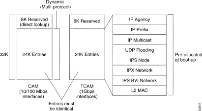
SDM partitions TCAM space into multiple regions. Each region is protocol specific. SDM interacts with the individual protocol control layer to store Layer 3 switching information. SDM consists of the following types of regions:
The enhanced Gigabit Ethernet interface module supports TCAM sizes of 32 KB, 64 KB, or 256 KB. Each entry in TCAM is 32 bits wide. Since SDM is responsible for managing TCAM space, SDM partitions the entire TCAM space for each protocol region based on user configuration. A change in the partition configuration takes effect only during the next system reboot.
Table 11-2 lists default partitioning for each protocol region in TCAM.
| Protocol Region | Lookup Type | Key Size | Default Size | No. of TCAM Entries |
|---|---|---|---|---|
The enhanced Gigabit Ethernet interface module is available with 32 KB, 64 KB, or 256 KB TCAM space. You can configure the various protocol regions in TCAM based on your requirements and on the size of TCAM on your Gigabit Ethernet interface module.
|
Note The enhanced Gigabit Ethernet interface module is available with 32 KB, 64 KB, or 256 KB TCAM space. The maximum SDM size is equal to the lowest TCAM size available among the interface modules present at the time of booting up the switch router. For example, if you have two interface modules with 64 KB and 256 KB TCAM sizes, then the maximum SDM size is 64 KB based on the lowest TCAM size available at bootup. |
To display and troubleshoot the SDM CAM configuration, use the following commands:
This section describes how to configure the SDM to change the size of the protocol-specific TCAM regions in the switch router.
To modify the default TCAM region sizes, use the following procedure:
Step 2 Modify the size of each region using the sdm size global configuration command.
Step 3 If desired, modify the SDM autolearn function using the [no] sdm autolearn global configuration command.
Step 4 Before reloading the system, verify that the desired sizing is reflected in the configuration (use the show running-config command).
Step 5 Reload the switch router to implement the new partitioning configuration.
The following process shows how to enlarge the size of the ip-prefix TCAM partition from 65,536 32-bit entries to 131,072 32-bit entries.
|
Note You must reload the system in order for the changes to take effect. |
Follow these steps to check and configure the SDM size:
Step 2 Use the sdm size ip-prefix k-entries command to change the ip-prefix from 65,536 32-bit bytes to 131,072 32-bit bytes. Using the k-entries parameter with the 128 (Kbytes) * 1024 multiples, equals 131,072 32-bit entries.
Step 3 Use the show running-config command to confirm the new configuration.
Step 4 Use the copy running-config startup-config command to write the new configuration to the NVRAM.
Step 5 Use the reload command to restart the Layer 3 enabled ATM switch router and reallocate the memory partitions.
Step 6 Use the show sdm size command to see the new configuration of the SDM CAM size.
If you determine that the SDM is configured incorrectly, refer to the "Configuring Switching Database Manager" chapter in the Layer 3 Switching Software Feature and Configuration Guide .
This section describes the following two common errors that might occur when you are trying to change the SDM size of the protocol-specific TCAM regions in the Layer 3 switch:
|
Note You must reload the system in order for the changes to take effect. |
The switch router generates a "Total protocol partitions exceed TCAM size!!" error while you are configuring the SDM partition sizes for the following reasons:
To solve the problem, specify a protocol partition size that does not exceed the total TCAM size, or specify the maximum size of the specified protocol partition.
In this example, the system generates an error when you attempt to specify more than 16,000 entries for the l2-switching region. The workaround is to ensure the specified size is less than or equal to the maximum region size, and that the sum of all of the protocol regions does not exceed 32K entries.
Follow these steps to eliminate the "Total protocol partitions exceed TCAM size!!" error while you are configuring the SDM partition sizes:
Step 2 Use the show sdm size command to display the size of the existing TCAM configuration.
Step 3 Use the show sdm internal all-regions command to display the size of the existing TCAM configuration for all regions.
Step 4 Confirm that the value entered in Step 1 does not exceed the total existing TCAM size, and try again.
The switch router generates the "%LSS-1-SDM: Region reached limit. Cannot accept more entries" syslog message at startup, or during normal system operation.
The following example shows that the system was unable to install one or more entries in the TCAM for the ip-adjacency and ip-prefix switching database regions. The following syslog messages indicate that the TCAM regions should be reconfigured to allow more entries for IP prefix and adjacency entries.
The system generates the syslog message for a specific protocol region when the system fails to install one or more entries in the TCAM because the specified region is full.
To fix this problem you must increase the size of the specified protocol region, using the sdm size command, and reload the system.
Use the process described in the "Configuring the Switching Database Manager" section to modify the ip-adjacency and ip-prefix switching database regions in the TCAM.
![]()
![]()
![]()
![]()
![]()
![]()
![]()
![]()
Posted: Wed Jan 22 01:44:50 PST 2003
All contents are Copyright © 1992--2002 Cisco Systems, Inc. All rights reserved.
Important Notices and Privacy Statement.