|
|

Table Of Contents
Adding a Higher Level of PNNI Hierarchy
Switch T1 Initial Configuration
Switch T2 Initial Configuration
Switch T3 Initial Configuration
Switch T4 Initial Configuration
Switch T5 Initial Configuration
Configuring Second Level of PNNI Hierarchy on Switches T3 and T4
Configuring the Link Between Switch T3 and Switch T4 for PNNI
Verifying Connectivity to All ATM Addresses and Deleting an Old Static Route on Switches T4 and T3
Adding a New Lowest Level of PNNI Hierarchy
Switch T1 Initial Configuration
Switch T2 Initial Configuration
Switch T3 Initial Configuration
Switch T4 Initial Configuration
Switch T5 Initial Configuration
Moving Switch T4 Down into a New Peer Group
Moving Switch SanFran.BldA.T5 Down into an Existing Peer Group
Restoring Auto-Summary on the LGN SanFran
Moving Switches T3, T1, and T2 Down into a New Peer Group
Restoring Autosummary on the LGN NewYork
PNNI Migration Examples
This appendix provides examples of how to migrate a flat network topology to a Private Network-Network Interface (PNNI) hierarchical network topology, and includes the following sections:
•
Adding a Higher Level of PNNI Hierarchy
•
Note
Adding a Higher Level of PNNI Hierarchy
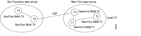
Figure A-1 shows an example network with two PNNI peer groups connected by an Interim Inter-Switch Signalling Protocol (IISP) interface.
Figure A-1 Two PNNI Peer Groups Connected by an IISP Interface
You can convert the network to a single hierarchical PNNI routing domain by configuring a second level of hierarchy in each peer group and converting the IISP interface to a PNNI interface, as shown in Figure A-2.
Figure A-2 Two-Level PNNI Hierarchical Network
The initial configuration for each ATM switch router is shown in the sections that follow. The commands used to migrate the network to a two-level PNNI hierarchical network (shown in Figure A-2) are also provided.
Switch T1 Initial Configuration
The initial configuration for switch NewYork BldB.T1 follows:
hostname NewYork.BldB.T1atm address 47.0091.4455.6677.1144.1011.1233.0060.3e7b.3a01.00atm router pnninode 1 level 72 lowestredistribute atm-staticSwitch T2 Initial Configuration
The initial configuration for switch NewYork BldB.T2 follows:
hostname NewYork.BldB.T2atm address 47.0091.4455.6677.1144.1011.1244.0060.3e5b.bc01.00atm router pnninode 1 level 72 lowestredistribute atm-staticTo display the reachability information, use the show atm route command.
NewYork.BldB.T2# show atm routeCodes: P - installing Protocol (S - Static, P - PNNI, R - Routing control),T - Type (I - Internal prefix, E - Exterior prefix, SE -Summary Exterior prefix, SI - Summary Internal prefix,ZE - Suppress Summary Exterior, ZI - Suppress Summary Internal)P T Node/Port St Lev Prefix~ ~~ ~~~~~~~~~~~~~~~~ ~~ ~~~ ~~~~~~~~~~~~~~~~~~~~~~~~~~~~~~~~~~~~~~~~~~~~~~~~~~~P I 9 0 UP 0 47.0091.4455.6677.1144.1011.1233/104P SI 1 0 UP 0 47.0091.4455.6677.1144.1011.1244/104R I 1 ATM2/0/0 UP 0 47.0091.4455.6677.1144.1011.1244.0060.3e5b.bc01/152R I 1 ATM2/0/0 UP 0 47.0091.4455.6677.1144.1011.1244.0060.3e5b.bc02/152R I 1 ATM2/0/0 UP 0 47.0091.4455.6677.1144.1011.1244.4000.0c/128P I 11 0 UP 0 47.0091.4455.6677.1144.1011.1255/104P E 11 0 UP 0 47.0091.4455.6677.22/64S E 1 ATM0/0/1 DN 0 47.0091.8200.0001.1/60Switch T3 Initial Configuration
The initial configuration for switch NewYork BldB.T3 follows:
hostname NewYork.BldB.T3atm address 47.0091.4455.6677.1144.1011.1255.0060.3e5b.c401.00atm router pnninode 1 level 72 lowestredistribute atm-staticinterface ATM0/0/2no ip addressatm route 47.0091.4455.6677.22... ATM0/0/2To display the reachability information, use the show atm route command. To display the interface type, use the show atm interface command:
NewYork.BldB.T3# show atm interface atm 0/0/2Interface: ATM0/0/2 Port-type: oc3suniIF Status: UP Admin Status: upAuto-config: enabled AutoCfgState: completedIF-Side: Network IF-type: IISPUni-type: not applicable Uni-version: V4.0<information deleted>
Note
Switch T4 Initial Configuration
The initial configuration for switch SanFran.BldA.T4 follows:
hostname SanFran.BldA.T4atm address 47.0091.4455.6677.2233.1011.1266.0060.3e7b.2001.00atm router pnninode 1 level 72 lowestredistribute atm-staticinterface ATM0/0/3no ip addressno atm auto-configurationatm iisp side user version 4.0atm route 47.0091.4455.6677.11... ATM0/0/3To display the reachability information, use the show atm route command. To display the interface type, side, and version, use the show atm interface command:
SanFran.BldA.T4# show atm interface atm 0/0/3Interface: ATM0/0/3 Port-type: oc3suniIF Status: UP Admin Status: upAuto-config: disabled AutoCfgState: not applicableIF-Side: User IF-type: IISPUni-type: not applicable Uni-version: V4.0Switch T5 Initial Configuration
The initial configuration for switch SanFran.BldA.T5 follows:
hostname SanFran.BldA.T5atm address 47.0091.4455.6677.2233.1011.1244.0060.3e7b.2401.00atm router pnninode 1 level 72 lowestredistribute atm-staticConfiguring Second Level of PNNI Hierarchy on Switches T3 and T4
The following example shows how to configure and display the second level of PNNI hierarchy on switches NewYork.BldB.T3 and SanFran.BldA.T4 (see Figure A-2):
Note
NewYork.BldB.T3# configure terminalNewYork.BldB.T3(config)# atm router pnniNewYork.BldB.T3(config-atm-router)# node 2 level 56NewYork.BldB.T3(config-pnni-node)# name NewYorkNewYork.BldB.T3(config-pnni-node)# exitNewYork.BldB.T3(config-atm-router)# node 1NewYork.BldB.T3(config-pnni-node)# parent 2NewYork.BldB.T3(config-pnni-node)# election leadership-priority 45NewYork.BldB.T3(config-pnni-node)# endNewYork.BldB.T3#SanFran.BldA.T4# configure terminalSanFran.BldA.T4(config)# atm router pnniSanFran.BldA.T4(config-atm-router)# node 2 level 56SanFran.BldA.T4(config-pnni-node)# name SanFranSanFran.BldA.T4(config-pnni-node)# exitSanFran.BldA.T4(config-atm-router)# node 1SanFran.BldA.T4(config-pnni-node)# parent 2SanFran.BldA.T4(config-pnni-node)# election leadership-priority 45SanFran.BldA.T4(config-pnni-node)# endSanFran.BldA.T4#Use the following commands to confirm the creation of the PNNI hierarchy:
SanFran.BldA.T4# show atm pnni local-nodePNNI node 1 is enabled and runningNode name: SanFran.BldA.T4System address 47.009144556677223310111266.00603E7B2001.01Node ID 72:160:47.009144556677223310111266.00603E7B2001.00Peer group ID 72:47.0091.4455.6677.2233.0000.0000Level 72, Priority 45 95, No. of interfaces 3, No. of neighbors 1Parent Node Index: 2<information deleted>PNNI node 2 is enabled and runningNode name: SanFranSystem address 47.009144556677223310111266.00603E7B2001.02Node ID 56:72:47.009144556677223300000000.00603E7B2001.00Peer group ID 56:47.0091.4455.6677.0000.0000.0000Level 56, Priority 0 0, No. of interfaces 0, No. of neighbors 0Parent Node Index: NONE<information deleted>SanFran.BldA.T4# show atm pnni hierarchyLocally configured parent nodes:Node ParentIndex Level Index Local-node Status Node Name~~~~~ ~~~~~ ~~~~~~ ~~~~~~~~~~~~~~~~~~~~ ~~~~~~~~~~~~~~~~~~~~~~1 72 2 Enabled/ Running SanFran.BldA.T42 56 N/A Enabled/ Running SanFranSanFran.BldA.T4# show atm pnni hierarchy networkSummary of active parent LGNs in the routing domain:Node Level Parent Node Name~~~~ ~~~~~ ~~~~~~ ~~~~~~~~~~~~~~~~~~~~~~~~~~~~~~~~~~~~~~~~~1 72 2 SanFran.BldA.T42 56 0 SanFranSanFran.BldA.T4# show atm pnni hierarchy network detailDetailed hierarchy network display:Number Of Network LGN Ancestors: 1Lowest Level (72) information:Node No.....: 1 Node Name: SanFran.BldA.T4Node's ID...: 72:160:47.009144556677223310111266.00603E7B2001.00Node's Addr.: 47.009144556677223310111266.00603E7B2001.01Node's PG ID: 72:47.0091.4455.6677.2233.0000.0000PGL No......: 1 PGL Name: SanFran.BldA.T4PGL ID......: 72:160:47.009144556677223310111266.00603E7B2001.00Level 56 ancestor information:Parent LGN..: 2 LGN Name: SanFranLGN's ID....: 56:72:47.009144556677223300000000.00603E7B2001.00LGN's Addr..: 47.009144556677223310111266.00603E7B2001.02LGN's PG ID.: 56:47.0091.4455.6677.0000.0000.0000LGN PGL No..: Unelected or unknownLGN's PGL ID: 0:0:00.000000000000000000000000.000000000000.00Configuring the Link Between Switch T3 and Switch T4 for PNNI
The following example shows how to configure the link between switch NewYorkBldB.T3 and SanFran.BldA.T4 for PNNI.
Note
SanFran.BldA.T4# configure terminalEnter configuration commands, one per line. End with CNTL/Z.SanFran.BldA.T4(config)# interface atm 0/0/3SanFran.BldA.T4(config-if)# atm auto-configurationSanFran.BldA.T4(config-if)# endSanFran.BldA.T4#%ATM-5-ATMSOFTSTART: Restarting ATM signalling and ILMI on ATM0/0/3.
Note
Verifying Connectivity to All ATM Addresses and Deleting an Old Static Route on Switches T4 and T3
The following example shows how to verify connectivity to all ATM addresses before deleting an old static route on switch T4:
SanFran.BldA.T4# show atm routeCodes: P - installing Protocol (S - Static, P - PNNI, R - Routing control),T - Type (I - Internal prefix, E - Exterior prefix, SE -Summary Exterior prefix, SI - Summary Internal prefix,ZE - Suppress Summary Exterior, ZI - Suppress Summary Internal)P T Node/Port St Lev Prefix~ ~~ ~~~~~~~~~~~~~~~~ ~~ ~~~ ~~~~~~~~~~~~~~~~~~~~~~~~~~~~~~~~~~~~~~~~~~~~~~~~~~~S E 1 ATM0/0/3 DN 0 47.0091.4455.6677.11/64
P I 12 0 UP 0 47.0091.4455.6677.1144/72P SI 2 0 UP 0 47.0091.4455.6677.2233/72P I 9 0 UP 0 47.0091.4455.6677.2233.1011.1244/104P SI 1 0 UP 0 47.0091.4455.6677.2233.1011.1266/104R I 1 ATM2/0/0 UP 0 47.0091.4455.6677.2233.1011.1266.0060.3e7b.2001/152R I 1 ATM2/0/0 UP 0 47.0091.4455.6677.2233.1011.1266.0060.3e7b.2002/152R I 1 ATM2/0/0 UP 0 47.0091.4455.6677.2233.1011.1266.4000.0c/128The following example shows how to delete the old static route from switch T4:
SanFran.BldA.T4# configure terminalEnter configuration commands, one per line. End with CNTL/Z.SanFran.BldA.T4(config)# no atm route 47.0091.4455.6677.11 atm0/0/3SanFran.BldA.T4(config)# endSanFran.BldA.T4#The following example verifies that the old static route on switch T4 has been deleted:
SanFran.BldA.T4# show atm routeCodes: P - installing Protocol (S - Static, P - PNNI, R - Routing control),T - Type (I - Internal prefix, E - Exterior prefix, SE -Summary Exterior prefix, SI - Summary Internal prefix,ZE - Suppress Summary Exterior, ZI - Suppress Summary Internal)P T Node/Port St Lev Prefix~ ~~ ~~~~~~~~~~~~~~~~ ~~ ~~~ ~~~~~~~~~~~~~~~~~~~~~~~~~~~~~~~~~~~~~~~~~~~~~~~~~~~P I 12 0 UP 0 47.0091.4455.6677.1144/72P SI 2 0 UP 0 47.0091.4455.6677.2233/72P I 9 0 UP 0 47.0091.4455.6677.2233.1011.1244/104P SI 1 0 UP 0 47.0091.4455.6677.2233.1011.1266/104R I 1 ATM2/0/0 UP 0 47.0091.4455.6677.2233.1011.1266.0060.3e7b.2001/152R I 1 ATM2/0/0 UP 0 47.0091.4455.6677.2233.1011.1266.0060.3e7b.2002/152R I 1 ATM2/0/0 UP 0 47.0091.4455.6677.2233.1011.1266.4000.0c/128The following example shows how to delete the old static route from switch T3:
NewYork.BldB.T3# configure terminalEnter configuration commands, one per line. End with CNTL/Z.NewYork.BldB.T3(config)# no atm route 47.0091.4455.6677.22 atm 0/0/2NewYork.BldB.T3(config)# endNewYork.BldB.T3#To verify the deletion of the old static route on switch T3, use the show atm route command.
Adding a New Lowest Level of PNNI Hierarchy
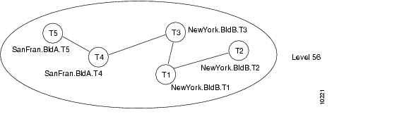
Figure A-3 shows an example network configured with only one level of PNNI hierarchy at level 56.
Figure A-3 One-Level PNNI Hierarchical Network
You can convert the network into a two-level hierarchical PNNI network by bringing each lowest level node down to level 72 and splitting the network into two peer groups. At the same time, you can add a second level of hierarchy at level 56. The resulting network topology is shown in Figure A-4.
Figure A-4 Two-Level PNNI Hierarchical Network
Note
Note
You can implement the migration process one ATM switch router at a time. As each ATM switch router is moved down to level 72, the ability to establish new connections across that ATM switch router is lost temporarily and then automatically restored. You can pause for long periods of time during the migration process without any harmful effects.
The initial configuration for each ATM switch router is shown in the sections that follow. The commands used to migrate the network to the two-level PNNI hierarchical network (shown in Figure A-4) are also provided.
Switch T1 Initial Configuration
The initial configuration for switch NewYork BldB.T1 follows:
hostname NewYork.BldB.T1atm address 47.0091.4455.6677.1144.1011.1233.0060.3e7b.3a01.00atm router pnninode 1 level 56 lowestredistribute atm-staticThe following example shows the output from the show atm route command for the switch:
NewYork.BldB.T1# show atm routeCodes: P - installing Protocol (S - Static, P - PNNI, R - Routing control),T - Type (I - Internal prefix, E - Exterior prefix, SE -Summary Exterior prefix, SI - Summary Internal prefix,ZE - Suppress Summary Exterior, ZI - Suppress Summary Internal)P T Node/Port St Lev Prefix~ ~~ ~~~~~~~~~~~~~~~~ ~~ ~~~ ~~~~~~~~~~~~~~~~~~~~~~~~~~~~~~~~~~~~~~~~~~~~~~~~~~~P SI 1 0 UP 0 47.0091.4455.6677.1144.1011.1233/104R I 1 ATM2/0/0 UP 0 47.0091.4455.6677.1144.1011.1233.0060.3e7b.3a01/152R I 1 ATM2/0/0 UP 0 47.0091.4455.6677.1144.1011.1233.0060.3e7b.3a02/152R I 1 ATM2/0/0 UP 0 47.0091.4455.6677.1144.1011.1233.0060.3e7b.3a03/152R I 1 ATM2/0/0 UP 0 47.0091.4455.6677.1144.1011.1233.0060.3e7b.3a04/152R I 1 ATM2/0/0 UP 0 47.0091.4455.6677.1144.1011.1233.0060.3e7b.3a05/152R I 1 ATM2/0/0 UP 0 47.0091.4455.6677.1144.1011.1233.4000.0c/128P I 9 0 UP 0 47.0091.4455.6677.1144.1011.1244/104P I 10 0 UP 0 47.0091.4455.6677.1144.1011.1255/104P I 12 0 UP 0 47.0091.4455.6677.2233.1011.1244/104P I 11 0 UP 0 47.0091.4455.6677.2233.1011.1266/104Switch T2 Initial Configuration
The initial configuration for switch NewYork BldB.T2 follows:
hostname NewYork.BldB.T2atm address 47.0091.4455.6677.1144.1011.1244.0060.3e5b.bc01.00atm router pnninode 1 level 56 lowestredistribute atm-staticSwitch T3 Initial Configuration
The initial configuration for switch NewYork BldB.T3 follows:
hostname NewYork.BldB.T3atm address 47.0091.4455.6677.1144.1011.1255.0060.3e5b.c401.00atm router pnninode 1 level 56 lowestredistribute atm-staticSwitch T4 Initial Configuration
The initial configuration for switch SanFran.BldA.T4 follows:
hostname SanFran.BldA.T4atm address 47.0091.4455.6677.2233.1011.1266.0060.3e7b.2001.00atm router pnninode 1 level 56 lowestredistribute atm-staticSwitch T5 Initial Configuration
The initial configuration for switch SanFran.BldA.T5 follows:
hostname SanFran.BldA.T5atm address 47.0091.4455.6677.2233.1011.1244.0060.3e7b.2401.00atm router pnninode 1 level 56 lowestredistribute atm-staticMoving Switch T4 Down into a New Peer Group
The first ATM switch router you move down into a new peer group at level 72 should be the ATM switch router you prefer as the peer group leader (PGL). Before moving down the first ATM switch router, configure the logical group node (LGN) for the second level of hierarchy on the ATM switch router.
Note
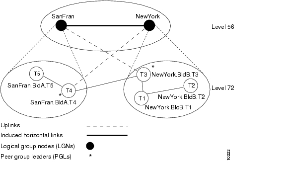
Figure A-5 shows the network topology after moving ATM switch router SanFran.BldA.T4 down into a new peer group at level 72 and establishing an LGN representing that peer group at level 56.
Figure A-5 Moving a Switch Down in the PNNI Hierarchy
Although ATM switch router SanFran.BldA.T5 and NewYork.BldB.T3 are not running any PGLs or LGNs in this example, these ATM switch routers must be capable of establishing the PNNI hierarchy. This capability allows them to bring up the induced horizontal links to the LGN SanFran, maintaining PNNI connectivity across the network. For this reason, we recommend that you upgrade all ATM switch routers to Cisco IOS Release 11.3T, WA4 or later, before configuring PNNI hierarchy.
The following example shows how to move switch SanFran.BldA.T4 down into a new peer group:
SanFran.BldA.T4# configure terminalEnter configuration commands, one per line. End with CNTL/Z.SanFran.BldA.T4(config)# atm router pnniSanFran.BldA.T4(config-atm-router)# node 2 level 56SanFran.BldA.T4(config-pnni-node)# name SanFranSanFran.BldA.T4(config-pnni-node)# no auto-summarySanFran.BldA.T4(config-pnni-node)# exitSanFran.BldA.T4(config-atm-router)# node 1SanFran.BldA.T4(config-pnni-node)# election leadership-priority 45SanFran.BldA.T4(config-pnni-node)# node 1 disableSanFran.BldA.T4(config-pnni-node)# node 1 level 72SanFran.BldA.T4(config-pnni-node)# parent 2SanFran.BldA.T4(config-pnni-node)# node 1 enableSanFran.BldA.T4(config-pnni-node)# endSanFran.BldA.T4#
Note
Moving Switch SanFran.BldA.T5 Down into an Existing Peer Group
After you move the first ATM switch router down to form a new peer group, you can move the remaining ATM switch routers down into the peer group one by one. You should move the ATM switch routers down in an order that keeps the peer group contiguous.
The following example shows how to move switch SanFran.BldA.T5 down into a peer group at level 72:
SanFran.BldA.T5# configure terminalEnter configuration commands, one per line. End with CNTL/Z.SanFran.BldA.T5(config)# atm router pnniSanFran.BldA.T5(config-atm-router)# node 1 disableSanFran.BldA.T5(config-pnni-node)# node 1 level 72 enableSanFran.BldA.T5(config-pnni-node)# endSanFran.BldA.T5#
Note
To verify the configuration, use the show atm pnni local-node and show atm pnni hierarchy commands. For examples of these commands, see the " "Configuring Second Level of PNNI Hierarchy on Switches T3 and T4" section .
You can configure one or more of the ATM switch routers that have been moved down into the peer group as a backup PGL. The following example shows how to configure SanFran.BldA.T5 as a backup PGL for the peer group SanFran (see Figure A-4):
SanFran.BldA.T5# configure terminalEnter configuration commands, one per line. End with CNTL/Z.SanFran.BldA.T5(config)# atm router pnniSanFran.BldA.T5(config-atm-router)# node 2 level 56SanFran.BldA.T5(config-pnni-node)# name SanFranSanFran.BldA.T5(config-pnni-node)# no auto-summarySanFran.BldA.T5(config-pnni-node)# exitSanFran.BldA.T5(config-atm-router)# node 1SanFran.BldA.T5(config-pnni-node)# election leadership-priority 10SanFran.BldA.T5(config-pnni-node)# parent 2SanFran.BldA.T5(config-pnni-node)# endSanFran.BldA.T5#SanFran.BldA.T5# show atm pnni local-nodePNNI node 1 is enabled and runningNode name: SanFran.BldA.T5System address 47.009144556677223310111244.00603E7B2401.01Node ID 72:160:47.009144556677223310111244.00603E7B2401.00Peer group ID 72:47.0091.4455.6677.2233.0000.0000Level 72, Priority 10 10, No. of interfaces 2, No. of neighbors 1Parent Node Index: 2<information deleted>PNNI node 2 is enabled and not runningNode name: SanFranSystem address 47.009144556677223310111244.00603E7B2401.02Node ID 56:72:47.009144556677223300000000.00603E7B2401.00Peer group ID 56:47.0091.4455.6677.0000.0000.0000Level 56, Priority 0 0, No. of interfaces 0, No. of neighbors 0Parent Node Index: NONE<information deleted>SanFran.BldA.T5# show atm pnni hierarchyLocally configured parent nodes:Node ParentIndex Level Index Local-node Status Node Name~~~~~ ~~~~~ ~~~~~~ ~~~~~~~~~~~~~~~~~~~~ ~~~~~~~~~~~~~~~~~~~~~~1 72 2 Enabled/ Running SanFran.BldA.T52 56 N/A Enabled/ Not Running SanFranSanFran.BldA.T5# show atm pnni hierarchy networkSummary of active parent LGNs in the routing domain:Node Level Parent Node Name~~~~ ~~~~~ ~~~~~~ ~~~~~~~~~~~~~~~~~~~~~~~~~~~~~~~~~~~~~~~~~1 72 14 SanFran.BldA.T514 56 0 SanFranRestoring Auto-Summary on the LGN SanFran
After all the nodes destined for the new peer group migrate into the peer group, you can restore auto-summary to reduce the number of reachable address prefixes advertised by the LGN.
The following example shows how to enable auto-summary on the LGN SanFran:
SanFran.BldA.T5# configure terminalEnter configuration commands, one per line. End with CNTL/Z.SanFran.BldA.T5(config)# atm router pnniSanFran.BldA.T5(config-atm-router)# node 2SanFran.BldA.T5(config-pnni-node)# auto-summarySanFran.BldA.T5(config-pnni-node)# endSanFran.BldA.T5#The following example shows how to verify the configuration:
SanFran.BldA.T5# show atm pnni summaryCodes: Node - Node index advertising this summaryType - Summary type (INT - internal, EXT - exterior)Sup - Suppressed flag (Y - Yes, N - No)Auto - Auto Summary flag (Y - Yes, N - No)Adv - Advertised flag (Y - Yes, N - No)Node Type Sup Auto Adv Summary Prefix~~~~ ~~~~ ~~~ ~~~~ ~~~ ~~~~~~~~~~~~~~~~~~~~~~~~~~~~~~~~~~~~~~~~~~~~~~~~~~~1 Int N Y Y 47.0091.4455.6677.2233.1011.1244/1042 Int N Y N 47.0091.4455.6677.2233/72The switch that contains the active PGL is configured similarly:
SanFran.BldA.T4# configure terminalEnter configuration commands, one per line. End with CNTL/Z.SanFran.BldA.T4(config)# atm router pnniSanFran.BldA.T4(config-atm-router)# node 2SanFran.BldA.T4(config-pnni-node)# auto-summarySanFran.BldA.T4(config-pnni-node)# endSanFran.BldA.T4#The following examples show how to verify the configuration:
SanFran.BldA.T4# show atm pnni summaryCodes: Node - Node index advertising this summaryType - Summary type (INT - internal, EXT - exterior)Sup - Suppressed flag (Y - Yes, N - No)Auto - Auto Summary flag (Y - Yes, N - No)Adv - Advertised flag (Y - Yes, N - No)Node Type Sup Auto Adv Summary Prefix~~~~ ~~~~ ~~~ ~~~~ ~~~ ~~~~~~~~~~~~~~~~~~~~~~~~~~~~~~~~~~~~~~~~~~~~~~~~~~~1 Int N Y Y 47.0091.4455.6677.2233.1011.1266/1042 Int N Y Y 47.0091.4455.6677.2233/72SanFran.BldA.T4# show atm routeCodes: P - installing Protocol (S - Static, P - PNNI, R - Routing control),T - Type (I - Internal prefix, E - Exterior prefix, SE -Summary Exterior prefix, SI - Summary Internal prefix,ZE - Suppress Summary Exterior, ZI - Suppress Summary Internal)P T Node/Port St Lev Prefix~ ~~ ~~~~~~~~~~~~~~~~ ~~ ~~~ ~~~~~~~~~~~~~~~~~~~~~~~~~~~~~~~~~~~~~~~~~~~~~~~~~~~P I 12 0 UP 0 47.0091.4455.6677.1144.1011.1233/104P I 11 0 UP 0 47.0091.4455.6677.1144.1011.1244/104P I 9 0 UP 0 47.0091.4455.6677.1144.1011.1255/104P SI 2 0 UP 0 47.0091.4455.6677.2233/72P I 13 0 UP 0 47.0091.4455.6677.2233.1011.1244/104P SI 1 0 UP 0 47.0091.4455.6677.2233.1011.1266/104R I 1 ATM2/0/0 UP 0 47.0091.4455.6677.2233.1011.1266.0060.3e7b.2001/152R I 1 ATM2/0/0 UP 0 47.0091.4455.6677.2233.1011.1266.0060.3e7b.2002/152R I 1 ATM2/0/0 UP 0 47.0091.4455.6677.2233.1011.1266.4000.0c/128Moving Switches T3, T1, and T2 Down into a New Peer Group
The following example shows how to move switch NewYork.BldB.T3 down into a new peer group:
NewYork.BldB.T3# configure terminalEnter configuration commands, one per line. End with CNTL/Z.NewYork.BldB.T3(config)# atm router pnniNewYork.BldB.T3(config-atm-router)# node 2 level 56NewYork.BldB.T3(config-pnni-node)# name NewYorkNewYork.BldB.T3(config-pnni-node)# no auto-summaryNewYork.BldB.T3(config-pnni-node)# exitNewYork.BldB.T3(config-atm-router)# node 1NewYork.BldB.T3(config-pnni-node)# election leadership-priority 45NewYork.BldB.T3(config-pnni-node)# node 1 disableNewYork.BldB.T3(config-pnni-node)# node 1 level 72NewYork.BldB.T3(config-pnni-node)# parent 2NewYork.BldB.T3(config-pnni-node)# node 1 enableNewYork.BldB.T3(config-pnni-node)# endNewYork.BldB.T3#The following example shows how to move switch NewYork.BldB.T1 down into a new peer group:
NewYork.BldB.T1# configure terminalEnter configuration commands, one per line. End with CNTL/Z.NewYork.BldB.T1(config)# atm router pnniNewYork.BldB.T1(config-atm-router)# node 1 disableNewYork.BldB.T1(config-pnni-node)# node 1 level 72 enableNewYork.BldB.T1(config-pnni-node)# endNewYork.BldB.T1#The following example shows how to move switch NewYork.BldB.T2 down into a new peer group:
NewYork.BldB.T2# configure terminalEnter configuration commands, one per line. End with CNTL/Z.NewYork.BldB.T2(config)# atm router pnniNewYork.BldB.T2(config-atm-router)# node 1 disableNewYork.BldB.T2(config-pnni-node)# node 1 level 72 enableNewYork.BldB.T2(config-pnni-node)# endNewYork.BldB.T2#The following examples show how to verify the results of the configuration:
NewYork.BldB.T2# show atm pnni local-nodePNNI node 1 is enabled and runningNode name: NewYork.BldB.T2System address 47.009144556677114410111244.00603E5BBC01.01Node ID 72:160:47.009144556677114410111244.00603E5BBC01.00Peer group ID 72:47.0091.4455.6677.1144.0000.0000Level 72, Priority 0 0, No. of interfaces 3, No. of neighbors 1Parent Node Index: NONE<information deleted>NewYork.BldB.T2# show atm routeCodes: P - installing Protocol (S - Static, P - PNNI, R - Routing control),T - Type (I - Internal prefix, E - Exterior prefix, SE -Summary Exterior prefix, SI - Summary Internal prefix,ZE - Suppress Summary Exterior, ZI - Suppress Summary Internal)P T Node/Port St Lev Prefix~ ~~ ~~~~~~~~~~~~~~~~ ~~ ~~~ ~~~~~~~~~~~~~~~~~~~~~~~~~~~~~~~~~~~~~~~~~~~~~~~~~~~P I 9 0 UP 0 47.0091.4455.6677.1144.1011.1233/104P I 13 0 UP 0 47.0091.4455.6677.1144.1011.1233/104P SI 1 0 UP 0 47.0091.4455.6677.1144.1011.1244/104P I 13 0 UP 0 47.0091.4455.6677.1144.1011.1244/104R I 1 ATM2/0/0 UP 0 47.0091.4455.6677.1144.1011.1244.0060.3e5b.bc01/152R I 1 ATM2/0/0 UP 0 47.0091.4455.6677.1144.1011.1244.0060.3e5b.bc02/152R I 1 ATM2/0/0 UP 0 47.0091.4455.6677.1144.1011.1244.4000.0c/128P I 11 0 UP 0 47.0091.4455.6677.1144.1011.1255/104P I 13 0 UP 0 47.0091.4455.6677.1144.1011.1255/104P I 12 0 UP 0 47.0091.4455.6677.2233/72NewYork.BldB.T2# show atm pnni hierarchy networkSummary of active parent LGNs in the routing domain:Node Level Parent Node Name~~~~ ~~~~~ ~~~~~~ ~~~~~~~~~~~~~~~~~~~~~~~~~~~~~~~~~~~~~~~~~1 72 13 NewYork.BldB.T213 56 0 NewYorkNewYork.BldB.T2# show atm pnni hierarchy network detailDetailed hierarchy network display:Number Of Network LGN Ancestors: 1Lowest Level (72) information:Node No.....: 1 Node Name: NewYork.BldB.T2Node's ID...: 72:160:47.009144556677114410111244.00603E5BBC01.00Node's Addr.: 47.009144556677114410111244.00603E5BBC01.01Node's PG ID: 72:47.0091.4455.6677.1144.0000.0000PGL No......: 11 PGL Name: NewYork.BldB.T3PGL ID......: 72:160:47.009144556677114410111255.00603E5BC401.00Level 56 ancestor information:Parent LGN..: 13 LGN Name: NewYorkLGN's ID....: 56:72:47.009144556677114400000000.00603E5BC401.00LGN's Addr..: 47.009144556677114410111255.00603E5BC401.02LGN's PG ID.: 56:47.0091.4455.6677.0000.0000.0000LGN PGL No..: Unelected or unknownLGN's PGL ID: 0:0:00.000000000000000000000000.000000000000.00Restoring Autosummary on the LGN NewYork
The following example shows how to restore autosummary on the LGN NewYork:
NewYork.BldB.T3# configure terminalEnter configuration commands, one per line. End with CNTL/Z.NewYork.BldB.T3(config)# atm router pnniNewYork.BldB.T3(config-atm-router)# node 2NewYork.BldB.T3(config-pnni-node)# auto-summaryNewYork.BldB.T3(config-pnni-node)# endNewYork.BldB.T3#The following examples show how to verify the configuration:
NewYork.BldB.T3# show atm pnni summaryCodes: Node - Node index advertising this summaryType - Summary type (INT - internal, EXT - exterior)Sup - Suppressed flag (Y - Yes, N - No)Auto - Auto Summary flag (Y - Yes, N - No)Adv - Advertised flag (Y - Yes, N - No)Node Type Sup Auto Adv Summary Prefix~~~~ ~~~~ ~~~ ~~~~ ~~~ ~~~~~~~~~~~~~~~~~~~~~~~~~~~~~~~~~~~~~~~~~~~~~~~~~~~1 Int N Y Y 47.0091.4455.6677.1144.1011.1255/1042 Int N Y Y 47.0091.4455.6677.1144/72NewYork.BldB.T3# show atm routeCodes: P - installing Protocol (S - Static, P - PNNI, R - Routing control),T - Type (I - Internal prefix, E - Exterior prefix, SE -Summary Exterior prefix, SI - Summary Internal prefix,ZE - Suppress Summary Exterior, ZI - Suppress Summary Internal)P T Node/Port St Lev Prefix~ ~~ ~~~~~~~~~~~~~~~~ ~~ ~~~ ~~~~~~~~~~~~~~~~~~~~~~~~~~~~~~~~~~~~~~~~~~~~~~~~~~~P SI 2 0 UP 0 47.0091.4455.6677.1144/72P I 12 0 UP 0 47.0091.4455.6677.1144.1011.1233/104P I 9 0 UP 0 47.0091.4455.6677.1144.1011.1244/104P SI 1 0 UP 0 47.0091.4455.6677.1144.1011.1255/104R I 1 ATM2/0/0 UP 0 47.0091.4455.6677.1144.1011.1255.0060.3e5b.c401/152R I 1 ATM2/0/0 UP 0 47.0091.4455.6677.1144.1011.1255.0060.3e5b.c402/152R I 1 ATM2/0/0 UP 0 47.0091.4455.6677.1144.1011.1255.4000.0c/128P I 10 0 UP 0 47.0091.4455.6677.2233/72
![]()
![]()
![]()
![]()
![]()
![]()
![]()
![]()
Posted: Mon Oct 11 09:14:17 PDT 2004
All contents are Copyright © 1992--2004 Cisco Systems, Inc. All rights reserved.
Important Notices and Privacy Statement.