|
|

Table Of Contents
Solution Architecture and Services
Basic Wholesale Voice and Dial Network Architectures
Basic Wholesale Voice Network Architecture
Basic Wholesale Dial Network Architecture
Merging Voice and Dial Services: Service Scenarios
Solution Architecture and Services
This chapter introduces a variety of topologies that make up the architecture of the Cisco ASAP Solution. This provides a foundation for understanding the deployment of various services, and introduces a variety of issues that must be taken into consideration for each service or service mix.
This chapter presents the following major topics:
•
Basic Wholesale Voice and Dial Network Architectures
•
Basic Wholesale Voice and Dial Network Architectures
The basic network architectures for wholesale voice (VoIP) and dial are not identical, assuming that each is specific to a single medium. As the utility of universal ports and universal gateways makes evident, such networks are becoming increasingly less practical for reasons of economics and management efficiency. Nevertheless, it is worthwhile to begin by discussing the differences.
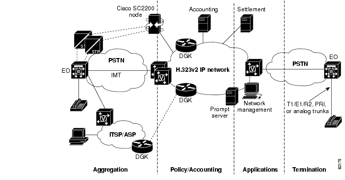
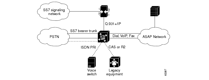
Basic Wholesale Voice Network Architecture
Figure 2-1 illustrates the basic architecture of a wholesale voice network. Note the following characteristics:
•
•
•
•
•
•
•
Note
Note
http://www.cisco.com/univercd/cc/td/doc/product/access/sc/rel7/soln/wv_rel1/index.htm
Documentation for the Cisco ASAP Solution will refer to these documents as needed.
Figure 2-1 Basic Wholesale Voice Network Architecture
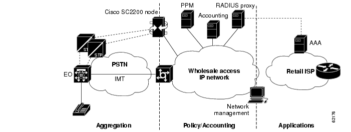
Basic Wholesale Dial Network Architecture
Figure 2-2 illustrates the basic architecture of a wholesale dial network. Note the following characteristics:
•
•
•
•
•
Note
Figure 2-2 Basic Wholesale Dial Network Architecture
Merging Voice and Dial Services: Service Scenarios
With the universal gateways (UGs), it is now possible to merge the voice and data worlds. An understanding of basic service scenarios, as well as their call flows, will make it easier to deploy a Cisco ASAP Solution successfully. Scenarios are presented below for the following services:
Note the following with respect to these services:
•
•
•
•
•
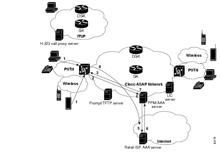
Dial and Wireless Data
Network Diagram
Figure 2-3 illustrates an example network and call flows for a dial and wireless data service. The call flow is described following the figure.
Note
Figure 2-3 Dial and Wireless Data
Dial and Wireless Call Flow
1.
2.
3.
4.
5.
6.
7.
8.
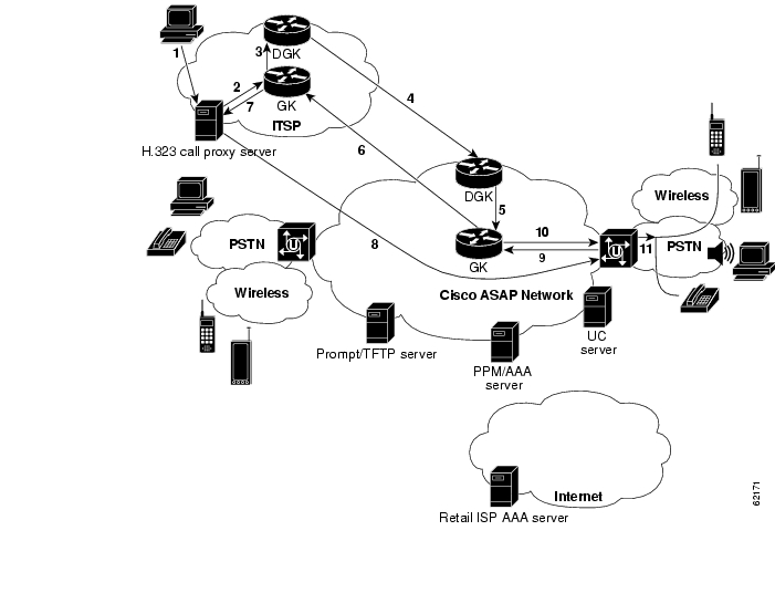
PC to Phone
Network Diagram
Figure 2-4 illustrates an example network and call flows for a PC to phone service. The call flow is described following the figure.
Figure 2-4 PC to Phone
PC-to-Phone Call Flow
1.
Note
http://www.cisco.com/univercd/cc/td/doc/product/access/sc/rel7/soln/wv_rel1/wvpg/index.htm
The user is assumed to be "registered" on the call proxy server, which authenticates the subscriber.
2.
In this example, the call terminates in another zone.
3.
4.
5.
6.
7.
8.
9.
10.
11.
Prepaid VoIP
Network Diagram
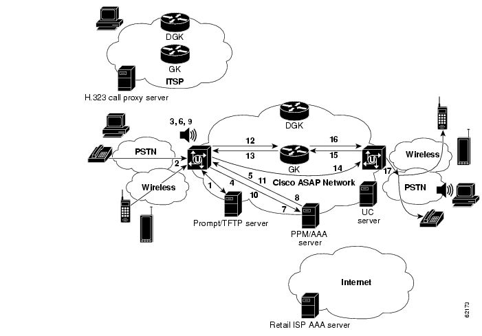
Figure 2-5 illustrates an example network and call flows for a RADIUS-based prepaid phone service. Ingress trunks are SS7, and egress trunks are SS7, CAS, or PRI. This is similar to Dial and Wireless Data, except that (1) RADIUS is used exclusively, (2) there are no interconnections between different SPs, and (3) the RAS messaging is illustrated. In addition, no DGK-DGK transactions are required as in PC to Phone, as this example assumes a single zone. The call flow is described following the figure.
Figure 2-5 Prepaid VoIP
Note
http://www.cisco.com/univercd/cc/td/doc/product/access/sc/rel7/soln/wv_rel1/wvpg/index.htm
Prepaid VoIP Call Flow
1.
Such a server is ideal for holding large and multiple audio files, which can be downloaded dynamically as required.
2.
On the OGW, the called number matches a dial peer with a call to an application of type, for example, "debit-card."
3.
4.
5.
6.
7.
8.
9.
10.
11.
Note
12.
13.
14.
15.
16.
17.
Phone to Phone
Network Diagram
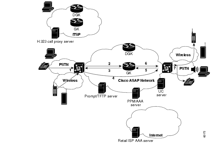
Figure 2-6 illustrates an example network and call flows for a simple phone-to-phone service. No transactions other than RAS are involved. The call flow is described following the figure.
Note
Figure 2-6 Phone to Phone
Phone-to-Phone Call Flow
1.
No interactive prompts are involved.
2.
3.
4.
5.
6.
7.
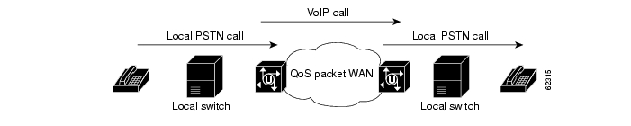
Long-Distance Toll Bypass
Long-distance toll bypass is an application of phone-to-phone service that is well-suited to the bulk call-routing needs of certain ISPs. By leveraging their existing data infrastructure and subscriber bases, ISPs can deliver carrier-class long-distance voice services over low-cost IP networks. With universal GWs as VoIP GWs, the Cisco ASAP Solution allows ISPs to carry voice traffic over packet networks, offering carrier-class domestic and international phone calls. Subscribers make long-distance calls from a regular telephone at home or office, or from other locations by entering an account number or password. No server lookup or IVR is needed. Calls are forwarded from the PSTN through the ingress UG to the egress UG, simply on the basis of the dial peer configuration, in a manner similar to TDM switching (see TDM Switching). Ingress trunks are SS7, and egress trunks are SS7, CAS, or PRI. Figure 2-7 illustrates the toll-bypass feature.
Note
Figure 2-7 Long-Distance Toll Bypass
Unified Communications
Unified communications services are provided by third parties, and include such solutions as voice mail over IP, fax store and forward, single-number reach, and so on. In addition, refer to Cisco's Internet Communications Software at the following URL:
http://www.cisco.com/warp/public/180/
Network Diagram
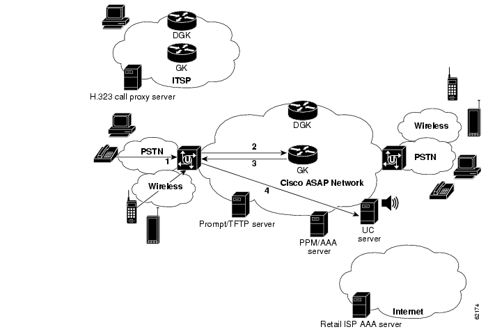
Figure 2-8 illustrates an example network and call flows for a unified communications (UC) service. This view is quite simplified. Depending on the size of the network, UC servers can require substantial capabilities (they perform considerably more signaling and functionality than is shown here) and are often clustered in server farms. The call flow is described following the figure.
Note
Figure 2-8 Unified Communications
Unified Communications Call Flow
1.
2.
3.
4.
Tip
http://www.cisco.com/univercd/cc/td/doc/cisintwk/intsolns/voipsol/um_isd.htm
TDM Switching
TDM switching is the ability of Cisco UGs to switch information directly between two DS0 circuits without affecting the data. Figure 2-9 illustrates this feature. The two calls, one incoming and one outgoing, are connected through a time slot interchange (TSI) function in the DS1/DS3 trunk card.
Figure 2-9 TDM Switching
This feature allows legacy systems to be maintained while new services are added. As demonstrated in Figure 2-10, the SP can migrate gracefully to Cisco ASAP technology while redirecting calls (dotted lines) to legacy equipment or PSTN switches as needed. With support for PRI and CAS, legacy systems can continue to be used.
Figure 2-10 Migration from Legacy and PSTN Services
The following additional benefits can also be realized:
•
•
Note
•
Support for DS0 Cross-Connections
TDM switching is supported on T1, E1, and DS3 interface cards. In Cisco UGs, both trunk and DSP cards provide onboard TSI functionality. DS0 channels used in TDM-switched calls can come from the same T1/E1 interface or different T1/E1 interfaces in the GW. Once two DS0s are cross-connected, the TSI circuitry is responsible for transmitting and receiving PCM data to and from the two DS0s. The circuitry also makes it possible to include any type of bearer data. Any ingress (received) DS0 on any DS1 or DS3 can be switched to an egress (transmit) DS0 on the same or a different DS1 or DS3.
Special Issues
Note the following special issues with respect to the DSP resources used in TDM switching:
•
When a CAS trunk is involved in TDM switching (on any Cisco GW), the DSP resource is required to set up the connection. This resource stays in the call path once the call is established. This is required to monitor the inband signaling (A, B, C, and D bits), so that the call can drop normally. With non-CAS calls, no DSP resources are used after the call connection is established.
•
If two CAS calls are involved in the TDM switching session, then each leg of the call uses one DSP resource. Once the call is established, both resources stay in the call path to monitor the inband signaling (A, B, C, and D bits), so that the call can drop normally.
•
VoIP calls using interactive voice response (IVR) in any portion of the call legs will also use DSP resources. When an incoming call uses IVR functionality, the DSP resource is not released until the call is released.
Support for Call Types
Table 2-1 shows the types of calls supported by TDM switching in the Cisco ASAP Solution.
Note
Table 2-2 shows the support for ISUP in VoIP calls originating from the PSTN.
T.38 Fax Service
The Cisco ASAP Solution supports Cisco T.38 Real-Time and Never-Busy Fax Service. For details, refer to Fax Services at the following URL:
http://www.cisco.com/univercd/cc/td/doc/cisintwk/intsolns/voipsol/fax_isd.htm
![]()
![]()
![]()
![]()
![]()
![]()
![]()
![]()
Posted: Wed Oct 6 12:37:42 PDT 2004
All contents are Copyright © 1992--2004 Cisco Systems, Inc. All rights reserved.
Important Notices and Privacy Statement.