|
|

Table Of Contents
Using Management and Shared Support Services
Resource and Network Management
Call Admission Control and RSVP
Traffic Engineering Guidelines
Challenges with Low-Speed Links (<1.5 Mbps)
Other Bandwidth and Core Related Issues
Optimizing the Performance of the Cisco SC2200
Before Configuring the LAC or LNS
An Example UG-to-RPMS Configuration
Useful Troubleshooting Commands
Overview of Authentication and Authorization on the Cisco AR
Using Management and Shared Support Services
Introduction
This chapter presents key issues related to the management and design of a Cisco ASAP Solution, including links to detailed installation and provisioning information for the following tools:
•
Resource and Network Management
Discusses how to ensure quality of service (QoS) in mixed voice and data networks, and other traffic-related design issues. Includes bothCisco IOS-based services such as basic and enhanced call admission control (CAC), as well as application-based resource and element management applications.
Includes IP precedence and low latency queuing (LLQ).
•
Architecture- and bandwidth-related tips for eliminating traffic bottlenecks, including both edge and core issues.
Discusses the details of enabling Cisco RPMS on a universal gateway (UG), including issues related to SS7 interconnect.
An overview of the functions provided by the Cisco Access Registrar (AR), a RADIUS-based AAA server, with references to user documentation and an installation guide.
An overview of the features of Cisco Redundant Link Manager (RLM), with references.
An overview of multilink PPP (MLP) and multichassis multilink PPP (MMP), with references.
An overview of the features of Simple Network Management Protocol (SNMP), with references.
A link to management information base files and application notes, with a list of MIBs suitable to the Cisco ASAP Solution.
Resource and Network Management
There are three basic steps to implementing satisfactory QoS:
•
•
•
Note
http://www.cisco.com/univercd/cc/td/doc/cisintwk/intsolns/qossol/qosvoip.htm
To help ensure QoS, a variety of resources can be managed from the Cisco IOS CLI by means of the following features:
•
These features are discussed below.
Call Admission Control and RSVP
This section presents the details of CAC features, both basic and enhanced. The latter includes Resource Reservation Protocol (RSVP).
Note
http://www.cisco.com/univercd/cc/td/doc/product/access/solution/asap/index.htm
RSVP is an IETF standard designed to support resource (such as bandwidth) reservations through networks of varying topologies and media. QoS requests are propagated to all routers along the data path, allowing the network to reconfigure itself to meet the desired level of service. RSVP is a remedy for voice/voice contention—the impact on all voice calls in a link caused by link overutilization—by ensuring the end-to-end availability of bandwidth. Once a voice link is utilized between 80 and 100 percent of capacity, jitter becomes significant. Jitter (the phase shift of digital pulses) results in the latency of voice packets, and an undesirable listening experience. Once link utilization exceeds 100%percent (statistically), the entire link is lost. RSVP is required if any link in the access network can become congested with voice traffic. It is implemented on the UG, as well as on any node (such as an edge router) in the access network.
RSVP is an enhancement to CAC that ensures QoS in Cisco H.323 VoIP networks. Its principles are identical to those of the IETF standard. RSVP-based CAC allows applications to request end-to-end QoS guarantees from the network. The Cisco VoIP Call Admission Control using RSVP feature synchronizes RSVP signaling with H.323 Version 2 signaling to ensure that the bandwidth reservation is established in both directions before a call moves to the alerting phase (ringing). This ensures that the called party's phone rings only after the resources for the call have been reserved. Using RSVP-based CAC, VoIP applications can reserve network bandwidth and react appropriately if bandwidth reservation fails.
Note
VoIP Call Admission Control:
http://www.cisco.com/univercd/cc/td/doc/cisintwk/intsolns/voipsol/cac.htm
VoIP Call Admission Control Using RSVP:
http://www.cisco.com/univercd/cc/td/doc/product/software/ios121/121newft/121t/121t5/dt4trsvp.htm
Call Admission Control for H.323 VoIP Gateways:
http://www.cisco.com/univercd/cc/td/doc/product/software/ios122/122newft/122limit/122x/122xa/122xa_2/ft_pfavb.htm
Like IETF RSVP, RSVP-based CAC is required if any link in the access network can become congested with voice traffic. It is implemented on the UG, as well as on any node (such as an edge router) in the access network.
Table 4-1 lists the call-denial rejection criteria (monitored resources or parameters) for voice and data calls.
Basic Call Admission Control
The key to managing contention is managing gateway resources. This differs between the PSTN side and the Cisco ASAP network side.
On the PSTN side, calls are neither delivered nor accepted if any set of required resources are all in use. In this case the following resources are monitored:
•
•
•
The above parameters are monitored by default on both ingress and egress UGs. If either of the above parameters are at a maximum at either end of the network, the call is not set up.
Enhanced CAC Features
The following discussion introduces the enhanced CAC commands that work within the H.323 protocol suite.
Resource Availability Indicator
On the Cisco ASAP network side, the gateway informs the GK if a resource threshold is exceeded. The flag is the RAI, or Resource Availability Indicator. The RAI is an H.323 CAC feature that informs the GK when no circuits (DS0s) are available.
The GK selects the UG on the basis of the UG's RAI status. In this case the following resources are monitored:
•
•
RAI messages indicate both the availability and unavailability of a UG, depending on the threshold for each that the user can set. RAIs let the GK select the best available UG at the outset, increasing call-completion rates and lowering postdial delay. After the GK receives an RAI from an overburdened UG, it will not assign calls to that UG.
There are two load thresholds: A high value determines when the UG sends the GK an "unavailable" RAI, and the low value determines when the UG sends the GK an "available" RAI. The syntax (available under config-gateway) is as follows:
resource threshold [all] [high percent-value] [low percent-value]
Note
Note
http://www.cisco.com/univercd/cc/td/doc/product/access/sc/rel7/soln/wv_rel1/wvpg/index.htm
Refer also to VoIP Call Admission Control, at the following URL:
http://www.cisco.com/univercd/cc/td/doc/cisintwk/intsolns/voipsol/cac.htm
That document also discusses RAI and PSTN fallback.
Further information about the PSTN fallback feature is also available at the following URL:
http://www.cisco.com/univercd/cc/td/doc/product/software/ios121/121newft/121t/121t3/dtpstnfb.htm
Note
http://www.cisco.com/univercd/cc/td/doc/product/software/ios122/122newft/122limit/122x/122xa/122xa_2/ft_pfavb.htm
A variety of features have been added to CAC to monitor both UG and network resources. On the UG side, the user can now define thresholds for monitoring UG health, as well as the actions that will take place when a threshold is exceeded.
If system (gateway) resources are not available to admit the call, two kinds of actions are possible:
•
•
If the interface-based resource is not available to admit the call, the call is dropped from the session protocol (in this case H.323).
There are options for call treatment, and restrictions can be placed on call rates. On the network side, both end-to-end bandwidth and end-to-end voice quality can be monitored. These enhancements are discussed below.
Gateway Health Resources
PSTN access gateways (UGs) can be monitored for overall health with respect to a variety of parameters:
•
•
•
Note
The global configuration command is call threshold, with the basic syntax as follows:
call threshold global trigger-name low percent high percent <busyout | treatment>With a global resource trigger such as the above, the default is busyout plus treatment. These global-only options work as follows.
With the option busyout, the Cisco Resource Unavailable Signaling feature set uses an autobusyout feature to transmit a busy signal on all T1/E1 channels in a trunk if the resource is not available. This feature works for both CAS and PRI trunks.
•
•
Table 4-2 lists the options for the triggers (trigger-name).
Values for low and high range from 1 to 100 (percent) for utilization triggers and from 1 to 10,000 (calls).
Note
When thresholds are exceeded, the designer needs to know how to treat the rejected call. This is discussed in the following section.
Call Treatment
Call treatment following a threshold overrun can take various forms, depending on whether the resource-challenged gateway (UG) is an originating gateway (OGW) or terminating gateway (TGW). Requirements are different on the TGW because the network expects reasons for the call rejection. The options of the global configuration command call treatment determine how calls should be processed when local resources are unavailable. This indicates whether the call should be disconnected (with cause code) or hairpinned, or a message or busy tone should be played to the user.
The use of this command will vary, depending on whether it is used on the OGW or the TGW.
On the OGW
•
•
•
The global configuration command is call treatment.
The basic syntax is as follows:
call treatment on
Caution
call treatment action <reject | playmsg | hairpin>The values of action are as follows:
•
•
•
On the TGW
•
•
The basic syntax in this case is as follows:
call treatment oncall treatment isdn-reject <cause-code 34-47>call treatment cause-code <busy | no-qos | no-resource>The parameters are as follows:
•
•
–
–
–
Call Rate Restriction
It is also possible to monitor the aggregate rate at which calls arrive, by using the global configuration command call spike. The syntax is as follows:
call spike <call-number> [ steps <number-of-steps> size <milliseconds> ]The parameters are as follows:
•
•
•
This configures the limit for the number of incoming calls (call-number) over the interval determined by size. Steps refer to the number of sliding windows that are applied to capture the numbers of incoming calls. This number is bursty, hence the term "spike." Figure 4-1 illustrates the relationship between the size and step parameters in the sliding window approach. Each "size" interval forms the beginning boundary of a new window. As bursts increase and must be captured, the number of steps (and hence windows) will need to be increased.
Figure 4-1 Sliding Windows Applied to Monitor Number of Incoming Calls
End-to-End Bandwidth
It is important to ensure that bandwidth is reserved in both directions before the call moves to the alerting phase, so that the called party's phone rings only after all the resources for the call have been reserved. The CAC feature that does this in Cisco H.323v2 VoIP networks is enabled through Resource Reservation Protocol (RSVP), the IP service that allows applications to request end-to-end QoS guarantees from the network. (RAI and RSVP can be considered as being mutually exclusive.)
Note
http://www.cisco.com/univercd/cc/td/doc/product/software/ios121/121newft/121t/121t5/dt4trsvp.htm
The command (enabled by default) call rsvp-sync enables synchronization between RSVP and the H.323 voice signaling protocol.
First ensure that bandwidth is reserved in both directions before ringing occurs:
call rsvp-syncTo set a timer for reservation requests (limiting the number of seconds to wait before proceeding with call setup or releasing the call according to the configured QoS level in dial peers), the command option resv-timer is used, with the following syntax:
call rsvp-sync resv-timer <seconds>The TGW knows what QoS is acceptable for the call, from its own configuration and the value included by the OGW in the H.323 SETUP message. If the TGW and the OGW are requesting a non-best-effort QoS and at least one reservation fails, the call will proceed as a best-effort call only if both gateways are willing to accept best-effort service. Otherwise, a Q.931 DISCONNECT message with cause code 49 (QoS unavailable) is generated.
End-to-End Voice Quality
It is important to ensure that delay, jitter, and packet loss between the ingress UG and remote IP addresses are within acceptable thresholds.
Voice quality can be determined by the degree of delay or packet loss, or can be based on ICPIF (the ITU G.113 Calculated Planning Impairment Factor). When a threshold is exceeded, the Cisco PSTN Fallback feature is invoked. Both ICPIF and PSTN fallback are discussed below.
Note
http://www.cisco.com/univercd/cc/td/doc/product/software/ios121/121newft/121t/121t3/dtpstnfb.htm
ICPIF Delay and Loss Thresholds
Delay and loss ICPIF thresholds use a feature called RTR (Response Time Reporter) to determine latency, delay, and jitter, in order to provide real-time ICPIF calculations before a call is established across an IP infrastructure. RTR packets emulate voice packets, receiving the same priority as voice throughout the entire network. RTR is superior to either data or ICMP ping packets for determining congestion levels.
Delay and loss thresholds are determined by the following call fallback command parameters:
call fallback threshold delay <delay-value> loss <loss-value>The parameters are as follows:
•
•
Alternatively, use the following to apply an ICPIF threshold to network traffic:
call fallback threshold icpif <threshold-value>The parameter is as follows:
•
Table 4-3 lists ICPIF threshold values and the corresponding speech quality they represent. When a threshold is exceeded, PSTN fallback is invoked. See PSTN Fallback, below.
Table 4-3 ICPIF Values
5
Very good
10
Good
20
Adequate
30
Limiting case
45
Exceptional limiting case
55
Customers likely to react strongly
The general idea behind G.113 is to calculate an impairment factor for every piece of equipment along the voice path, then add all factors to obtain total impairment. There are different types of impairments (noise, delay, echo, and so on), and the ITU divides them into five categories.
Note
http://www.itu.int.
You may also wish to consult with your Cisco account representative regarding the details of ICPIF provisioning.
PSTN Fallback
The Cisco PSTN Fallback feature has the following characteristics:
•
•
•
•
•
The network designer must then consider how to handle traffic when voice quality falls outside the defined thresholds. Here there are two options:
•
•
–
–
The above thresholds are ignored, but they enable the collection of statistics.
Caution
For details on using ICPIF within Cisco Voice Manager, refer to Managing Voice Quality with Cisco Voice Manager (CVM) and Telemate at the following URL:
http://www.cisco.com/warp/public/788/AVVID/cvmtelemate.html
Note
Additional QoS Remedies
This section discusses the following additional remedies that can be applied to ensure QoS:
•
IP Precedence
IP precedence is a remedy for voice and data contention by marking traffic for different priority classes. This technique is required if any link in the entire network can become congested—an extremely likely possibility. IP precedence is implemented at the UG edge interfaces, both voice and modem.
Table 4-4 lists traffic classes and types, along with their IP precedence numbers.
Table 4-4 Traffic Classes and Types, with IP Precedence Numbers
Voice bearer
RTP
5
Signaling
RTCP, RSVP, Q.931+/IP, H.323, etc.
3
Data
Best effort
0
Voice traffic is assigned the highest precedence, but related signaling is not far behind. Data, however, can tolerate latency with little effect on the user, and so is delivered simply in a "best effort" attempt.
Note
http://www.cisco.com/univercd/cc/td/doc/cisintwk/intsolns/qosvoip.htm
Low-Latency Queuing
The Cisco Low Latency Queuing (LLQ) feature, supported by the Cisco Resource Reservation Protocol (RSVP) feature, brings strict priority queuing to class-based weighted fair queuing (CBWFQ). Strict priority queuing allows delay-sensitive data such as voice to be dequeued and sent first (before packets in other queues are dequeued), giving delay-sensitive data preferential treatment over other traffic.
To guarantee the bandwidth required for voice, LLQ schedules signaling and voice traffic according to their traffic class. LLQ is implemented on any link in the network that can become congested by a combination of signaling, voice, and data traffic.
Note
http://www.cisco.com/univercd/cc/td/doc/product/software/ios120/120newft/120t/120t7/pqcbwfq.htm
In addition, LLQ requirements vary according to link bandwidth. In high-speed (>1.5 Mbps) links, both signaling and voice traffic are placed in a priority queue, with data in a best effort queue. With low-speed (<1.5 Mbps) links, where there naturally is less bandwidth to be shared among all required traffic types, signaling is placed in a weighted queue, assigning sufficient bandwidth to guarantee against data drops. Voice traffic is placed in a priority queue, and data again in a best effort queue.
RSVP is a network-control protocol that provides a means for reserving network resources (primarily bandwidth), to guarantee that applications achieve the desired QoS across the network. LLQ is an efficient queuing implementation that improves upon the weighted fair queuing (WFQ) algorithm used by RSVP.
Note
http://www.cisco.com/univercd/cc/td/doc/product/software/ios121/121newft/121t/121t3/rsvp_llq.htm
Refer also to Configuring RSVP Support for LLQ at the following URL:
http://www.cisco.com/univercd/cc/td/doc/product/software/ios122/122cgcr/fqos_c/fqcprt5/qcfrsllq.htm
RSVP/LLQ Integration
RSVP uses WFQ to provide fairness in flows and assign a low weight to a packet so it can attain priority. However, the RSVP queuing algorithm fails to minimize jitter. Whereas RSVP provides call admission control, the Cisco RSVP Support for Low Latency Queuing feature also provides the needed support for bandwidth and delay guarantees need for voice traffic.
Note
http://www.cisco.com/univercd/cc/td/doc/product/software/ios121/121newft/121t/121t3/rsvp_llq.htm
UGs have a software feature that sets and monitors CPU threshold to provide this service. This feature, known as the Cisco Call Admission Control Based on CPU Utilization feature, denies incoming calls that exceed a preconfigured threshold of system CPU load level. The feature rejects new digital calls (PRI, CAS, and ISDN), with minor disruption to system users.
Link Fragmentation and Interleaving
Large data packets can adversely delay delivery of small voice packets, reducing speech quality. Fragmenting these large data packets into smaller ones and interleaving voice packets among the fragments reduces jitter and delay. The Cisco IOS Link Fragmentation and Interleaving (LFI) feature helps satisfy the real-time delivery requirements of VoIP.
Note
http://www.cisco.com/warp/public/788/voice-qos/voip-mlppp.html
Traffic Engineering Guidelines
The following topics discuss additional traffic-engineering challenges posed by a Cisco ASAP Solution network, the majority of which are related to varying bandwidth throughout the network:
•
•
•
•
•
Challenges with Low-Speed Links (<1.5 Mbps)
With bandwidth under T1 rates, extra attention must be paid to preventing voice quality from suffering. With respect to voice/voice and voice/data contention, the remedies in Table 4-1 apply here. However, two new challenges arise in low-speed links and must be dealt with:
Packet Residency
Packet residency, also known as serialization delay, is the term for the effect large data packets have on voice quality. Data packets can be so large that the time it takes to transmit one large packet over a low-speed WAN link can exceed the voice delay budget. Interleaving mechanisms break large data packets into smaller ones, so that small voice packets can be inserted, or interleaved, between data fragments to ensure timely voice transport. The Cisco Multilink Point-to-Point Protocol (MLP) feature, and more recently the Cisco Multichannel Multilink PPP (MMP) feature, is designed to do this. (See Configuring Multilink PPP.)
Bandwidth Consumption
Managing bandwidth consumption is a top priority over low-speed links. Techniques include the use of low-bit-rate audio codecs, RTP (Real-Time Transport Protocol) header compression, and voice activity detection (VAD). VAD detects periods of silence and prevents "empty" packets from being transmitted during those periods.
Other Bandwidth and Core Related Issues
This section discusses additional issues, related to the following topics:
•
•
•
•
Gateway with High-Speed Egress Interface
Figure 4-2 highlights a UG with a high-speed egress interface. Refer to Table 4-5 for remedies to be applied.
Figure 4-2 Gateway with High-Speed Egress Interface
Gateway with Low-Speed Egress Interface
Figure 4-3 highlights a UG with a low-speed egress interface. Refer to Table 4-5 for remedies to be applied.
Figure 4-3 Gateway with Low-Speed Egress Interface
Edge Router with High-Speed Egress Interfaces
Figure 4-4 highlights an edge router with high-speed egress interfaces. Refer to Table 4-5 for remedies to be applied.
Figure 4-4 Edge Router with a High-Speed Egress Interface
Edge Router with Low-Speed Egress Interfaces
Figure 4-5 highlights an edge router with low-speed egress interfaces. Refer to Table 4-5 for remedies to be applied.
Figure 4-5 Edge Router with Low-Speed Egress Interfaces
Gateway with High-Speed Egress Interface
Figure 4-6 highlights a UG with a high-speed egress interface. Refer to Table 4-5 for remedies to be applied.
Figure 4-6 Gateway with High-Speed Egress
Core Issues
Table 4-5 lists the issues related to bandwidth and the network core, with recommended remedies.
Table 4-5 Bandwidth and Core Related Issues and Remedies
UG
High-speed egress
WAN connection between PSTN UG and edge router;
see Figure 4-2•
•
Low-speed egress
Serial connection between PSTN UG and edge router;
see Figure 4-3•
•
•
•
•
•
•
•
Edge router
High-speed egress interfaces
WAN connection between edge router and (1) Cisco ASAP network and (2) PSTN UG;
see Figure 4-4•
•
•
Low-speed egress interfaces
Serial connection between edge router and (1) Cisco ASAP network and (2) PSTN UG;
see Figure 4-5•
•
•
•
•
Cisco ASAP core
Congestion
Any link that can become congested through a combination of signaling, voice, and data traffic;
see Figure 4-6•
•
•
1 Assuming voice/voice contention is enabled and device is IP aware.
2 Assuming device is IP aware and supports LLQ.
Optimizing the Performance of the Cisco SC2200
Figure 4-7 illustrates two optimization models for SS7 interconnect. One is optimized for simultaneous calls, the other for calls per second (CPS).
Caution
In most cases, however, optimizing for CPS will be sufficient.
Figure 4-7 Two Optimization Models: Simultaneous Calls and Calls per Second
L2TP Tunneling and VPDNs
As background to the following abbreviated discussion, refer to Layer 2 Tunnel Protocol at the following URL:
http://www.cisco.com/univercd/cc/td/doc/product/software/ios120/120newft/120t/120t1/l2tpt.htm
Note
http://www.cisco.com/univercd/cc/td/doc/product/access/solution/asap/index.htm
Refer also to L2TP Network Server, for installation and related information.
The document Layer 2 Tunnel Protocol illustrates the relationship between what is referred to as the LAC, or local access concentrator, and the LNS. The LAC is essentially the NAS, or in our case a UG. VPDN commands are used in conjunction with commands to enable AAA. The LNS can be a Cisco AS5000 series UG, but larger networks may require a Cisco 7200 or Cisco 7400 series.
To create a VPDN, or virtual private data (or dial) network, you must do the following on both the UG and the LNS:
•
Note
Before Configuring the LAC or LNS
Do one of the following before configuring the LAC (UG) or LNS for VPDN using L2TP:
•
•
Configuring VPDN on the LAC
In the following basic example, a dial subscriber accesses the LAC through an ISP or the PSTN. The UG, in turn, communicates with the LNS through an L2TP tunnel. See Configuring a Gateway for Universal Service. Complete the following procedures:
•
Note
http://www.cisco.com/univercd/cc/td/doc/product/software/ios122/122cgcr/fdial_c/index.htm
Perform Global LAC Configuration
The following steps are done in global configuration mode.
Step 1
aaa new-modelStep 2
aaa authentication ppp default localStep 3
Note
LAC(config)# vpdn enableStep 4
LAC(config)# vpdn-group 1Any groups defined on the LAC must also be defined on the LNS. See Edit LNS VPDN Parameters.
Edit LAC VPDN Parameters
You can begin the following while still in global configuration mode.
Step 1
a.
LAC(config)# vpdn-group 1
Note
The following is done in VPDN configuration mode, which changes to request-dialin mode (config-vpdn-req-dialin) to reflect the fact that we are configuring the access gateway.
Step 2
a.
LAC(config-vpdn)# request-dialinThe prompt will change to reflect the fact that we are configuring the request side of the tunnel.
b.
LAC(config-vpdn-req-in)# protocol l2tp
Note
You must select a protocol before you can establish a tunnel secret and tunnel name.
c.
LAC(config-vpdn-req-in)# domain cisco.comd.
LAC(config-vpdn-req-in)# dnis <dnis number>
Note
e.
LAC(config-vpdn-req-in)# exitStep 3
LAC(config-vpdn)# initiate-to <IP address>Step 4
a.
LAC(config-vpdn)# l2tp tunnel password <tunnel-secret>b.
LAC(config-vpdn)# local name <tunnel-name>
Note
c.
LAC(config-vpdn)# username <tunnel-name> password <tunnel-secret>
Note
Step 5
LAC(config-vpdn)# vpdn search-order { domain | dnis | domain dnis | dnis domain }If both keywords are entered, the UG will search the criteria in the order in which they are entered.
Tip
Step 6
Configuring VPDN on the LNS
The following basic example configures VPDN on the L2TP network server (LNS), or host (also referred to as the tunnel server). The establishment of the username and password is not shown. This is very similar (and parallel) to Configuring VPDN on the LAC. Complete the following procedures:
•
Perform Global LNS Configuration
The following steps are done in global configuration mode. Here we also create a virtual template on the LNS.
Step 1
aaa new-modelStep 2
aaa authentication ppp default localStep 3
a.
interface virtual-template <number)New interfaces, as they are assigned, will copy (clone) the attributes of the virtual template to create virtual access interfaces. (There is no correspondence between the virtual template and the VPDN group.)
b.
ip unnumbered <interface-type><number>
Note
c.
ppp authentication chapStep 4
no ip mroute-cacheStep 5
Note
LNS(config)# vpdn enableStep 6
LNS(config)# vpdn-group 1Edit LNS VPDN Parameters
Begin the following while still in global configuration mode.
Step 1
LNS(config)# vpdn-group 1The following is done in VPDN configuration mode, which changes on the LNS to accept-dialin mode (config-vpdn-acc-dialin), to reflect the fact that we are configuring the tunnel server.
Step 2
a.
LNS(config-vpdn)# accept-dialinb.
LNS(config-vpdn-acc-in)# protocol l2tp
Note
c.
LNS(config-vpdn-acc-in)# virtual-template <number>The number will be the same as that established in Perform Global LAC Configuration.
d.
LNS(config-vpdn-acc-in)# exitStep 3
a.
LNS(config-vpdn)# l2tp tunnel password <tunnel-secret>b.
LNS(config-vpdn)# local name <tunnel-name>c.
LNS(config-vpdn)# username <tunnel-name> password <tunnel-secret>
Note
Step 4
LNS(config-vpdn)# terminate-from <hostname>
Note
Enabling Cisco RPMS 1.x
This section is primarily a detailed discussion of the configuration required on the UG in its function as a NAS in support of dial services. To install and configure a Cisco RPM server, refer to Cisco Resource Pool Manager Server.
This discussion addresses Cisco RPMS prior to Release 2.0. Refer to Cisco Resource Pool Manager Server 1.1 at the following URL:
http://www.cisco.com/univercd/cc/td/doc/product/access/acs_soft/rpms/rpms_1-1/index.htm
See also Enabling Local RPM.
Caution
Overview
There are five principle components to enabling a UG to interact with a Cisco RPMS:
•
•
•
•
•
Caution
Required Activities
The required configuration activities, in the recommended sequence, are as follows:
1.
2.
3.
4.
5.
6.
7.
8.
9.
10.
11.
Optional Activities
There are two optional activities:
Tip
The following topics are also presented in this section:
•
•
•
Basic Configuration
Step 1
Use the following syntax to define an AAA server group of Cisco RPM servers.
a.
aaa new-model
Caution
b.
aaa group server tacacs+ <name>where name is local to the UG but must match the name defined in Step 5, Enable resource pooling to the Cisco RPMS..
c.
server <hostname/ipaddress>d.
Note
Step 2
The enabling of multithreaded processing for AAA transactions can be considered essential, to keep transaction latency at a minimum. The simple syntax is as follows.
aaa process <n>where n is an integer that determines the number of AAA processes.
Note the following suggestions and caveats.
•
•
•
•
•
Step 3
You must configure a tacacs-server definition for each RPMS listed under the AAA server group. See Step 1, Define an AAA server group of Cisco RPMSs..
Use the following syntax to define a Cisco RPM server.
tacacs-server host <hostname/ipaddress> key <string>where string is an identifying keyword.
Note
Step 4
The source IP address used for TACACS+ packets from the UG must match that configured in the RPMS or that returned by a name server lookup.
Use the following syntax to define a source interface.
ip tacacs source-interface <interface>where interface is typically a loopback interface that ensures there is no dependence on a physical interface being up.
Step 5
Use the following syntax to enable resource pooling to the Cisco RPM server.
resource-pool aaa protocol group <name>where name is a link to the AAA group defined in Step 1, Define an AAA server group of Cisco RPMSs..
Note
Note
Step 6
VSAs provide additional information for PPP accounting records, such as overflow flags, customer profile matches, and so on.
Use the following syntax to enable additional accounting attributes. Here we associate PPP accounting with the resource pool.
resource-pool aaa accounting pppSee also Enable VSAs in accounting records..
Note
http://www.cisco.com/univercd/cc/td/doc/product/access/sc/rel7/soln/wv_rel1/wvpg/index.htm
Step 7
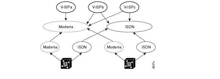
Each UG contributes resources to common pools. Customers then access the pooled resources through RPMS. Figure 4-8 illustrates virtual resource groups (for virtual ISPs) across multiple access servers (UGs in our case). Resource groups on individual UGs must have the same names.
Figure 4-8 Virtual Resource Groups Serving Virtual ISPs
Do the following to define resource groups.
a.
b.
Note
resource-pool group resource <name>where name is used by the RPMS to reference resources available on the UG. Resource groups of the same name must be created on the RPMS for them to be used. Resource groups with the same name allow the pooling of those resources across multiple UGs.
c.
range port <shelf/slot/port> <shelf/slot/port>
Port location format is platform dependent, and may also be slot/port. In this example the two shelf/slot/port values define the beginning and end of a range. Noncontiguous ranges can be defined by separate range port statements. Note the following example:
resource-pool group resource modemsrange port 1/4/0 1/4/143range port 1/6/0 1/6/143
Note
d.
resource-pool group resource <name>range limit <n>where n is an integer that does not exceed the number of HDLC framers on the UG. Note the following example:
resource-pool group resource modemsrange limit 256e.
–
–
–
Step 8
Now you are ready to turn resource pooling on. To do so before completing the configuration would cause calls to be redirected unnecessarily through this feature, with undesirable consequences.
To enable resource pooling, use the following global configuration command:
resource-pooling enableStep 9
You must enable the UG to send administrative updates to the Cisco RPMS. Use the following syntax to enable administrative updates.
tacacs-server administration
Caution
Step 10
You can limit the peak call rate by defining the maximum depth of the resource monitor queue. Use the following syntax to limit the peak call rate.
resource-pool throttle <n> <cause-code>where
–
–
–
The UG will reject calls if the number of calls in the resource monitor queue reach the throttle limit set by n.
Step 11
Now you must enable VSA processing on the UG. This is essential to sending VSAs (including such items as overflow flags) to the Cisco RPMS. See Enable additional accounting attributes..
Use the following syntax to enable VSAs on the UG.
radius-server vsa send accountingThe above is used in conjunction with AAA accounting and AAA server definitions defined in previous steps.
Note
http://www.cisco.com/univercd/cc/td/doc/product/access/sc/rel7/soln/wv_rel1/wvpg/index.htm
Summary of Key Steps
The following summarizes the preceding steps:
aaa group server tacacs+ <name>server <hostname/ipaddress>aaa process <n>tacacs-server host <hostname/ipaddress> key <string>ip tacacs source-interface <interface>resource-pool aaa protocol group <name>resource-pool aaa accounting pppresource-pool group resource <name> (see Note below)range port <location-start> <location-end>range limit <x>resource-pooling enabletacacs-server administrationresource-pool throttle <n> <cause-code>radius-server vsa send
Note
Enabling VPDN (Optional)
You can configure VPDN information on an RPMS or an AAA server. Use the following command:
vpdn enable
Note
This is the only configuration required if the RPMS provides VPDN definitions. VPDN definitions may also be provided by an AAA server. However, a VPDN check is always made to the Cisco RPMS first.
Configuring SGBP (Optional)
If more than one home gateway is specified, sessions are load-balanced in "round-robin" fashion among the IP addresses, in which the next available address is used in series. For Multilink PPP (MLP) connections as are used in ISDN, half of the packets will be lost. With SGBP (Stack Group Bidding Protocol), the UG is configured to belong to groups of peers called stack groups. All members of a stack group are peers, and therefore do not need a permanent "lead" UG.
After a connection is established with one member of a stack group, that member owns the call. If a second call comes in from the same client and a different UG answers the call, the first UG establishes a VPDN tunnel and forwards all packets belonging to the call to the (new) UG that owns the call.
Note
For an illustration of this issue and configuration information, refer to Configuring Stack Group Bidding Protocol at the following URL:
http://www.cisco.com/univercd/cc/td/doc/product/access/acs_soft/rpms/rpms_1-0/rpmsconf/app_sgbp.htm
An Example UG-to-RPMS Configuration
<---snip--->!aaa group server tacacs+ RPMSserver 172.19.50.122server 172.19.50.125!aaa processes 20!<---snip--->!resource-pooling enable!resource-pool group resource modemsrange port 1/4/0 1/4/143range port 1/6/0 1/6/143!resource-pool group resource ISDNrange limit 256!resource-pool aaa accounting pppresource-pool aaa protocol group RPMS<---snip--->a!ip tacacs source-interface FastEthernet0/1!<---snip--->!vpdn enable!<---snip--->!tacacs-server host 172.19.50.122 key vt-labtacacs-server host 172.19.50.125 key vt-labtacacs-server administration!<---snip--->!radius-server vsa send accounting<---snip--->Useful Troubleshooting Commands
The following show commands provide a variety of resource pool information.
•
•
ASAP_UG#show resource-pool resource modems144 resources in the resource group8 resources currently active248 calls accepted in the resource group0 calls rejected due to resource unavailable0 calls rejected due to resource allocation errorsnever since last clear commandSS7 Resource Groups
Predefined SS7 resource groups are automatically created when resource pooling is enabled to a Cisco RPMS from a UG that is configured for SS7 interconnect. (See Enable resource pooling to the Cisco RPMS.). An SS7 resource group is created for each call type that can be terminated on that system. The maximum number of resources that are available for each call type are placed in the associated resource group.
The following message will appear to indicate the resource groups have been created successfully:
SS7/RPM/RPMS are all configured and the predefined resource groups will be createdWhen SS7 interconnect is enabled on the UG, resource groups are defined, and the following command is issued:
resource-pool aaa protocol group <name>the following error message will be displayed:
"You must remove all the configured resource group(s) and re-enter this command for
SS7/RPM/RPMS interworking"
To remedy this, delete any defined resource groups on the UG and then reenter the command.
Table 4-7 lists the current predefined SS7 resource groups. Their types are self-explanatory.
Table 4-7 Predefined SS7 Resource Groups
rg_ss7_mica
rg_ss7_nextport
rg_ss7_digital
rg_ss7_v110
rg_ss7_v120
Caution
•
•
•
res-group <name> cannot be created/modified when SS7/RPM/RPMS are all enabledTable 4-8 lists the default RPMS SS7 resource group mappings.
An Example SS7 Resource Group
The following is an example of an SS7 resource group.
resource-pool group resource rg_ss7_digitalrange limit 192!resource-pool group resource rg_ss7_v120range limit 192!resource-pool group resource rg_ss7_nextportrange port 2/0 2/107range port 3/0 3/107range port 4/0 4/107range port 5/0 5/107range port 6/0 6/107range port 7/0 7/107Enabling Cisco AR
Cisco Access Registrar 1.7 is the most recent version of the Cisco AR access policy server, and is documented at the following URL:
http://www.cisco.com/univercd/cc/td/doc/product/rtrmgmt/cnsar/1_7/
It is beyond the scope of the current document to detail the provisioning of the Cisco AR server.
Note
Refer to the following documents for the details of understanding and using Cisco AR:
•
•
•
•
Overview of Authentication and Authorization on the Cisco AR
The following brief overview provides basic information about how Cisco Access Registrar (AR) performs the basic RADIUS functions of authentication and authorization as defined in Internet RFC 2865. An understanding of the process can be helpful in troubleshooting.
Authentication and authorization are defined as follows.
•
•
Note
http://www.cisco.com/univercd/cc/td/doc/product/access/sc/rel7/soln/wv_rel1/wvpg/index.htm
Basic Authentication and Authorization
The Cisco AR server provides authentication and authorization service to clients that are network access servers (UGs in the case of the Cisco ASAP Solution). The following paragraphs describe the steps to a connection.
1.
2.
3.
a.
b.
An incoming script can examine and change the attributes of the request packet or the environmental variables that can affect subsequent processing. On the basis of default values or scripts, the AR server chooses a service to authenticate and authorize the user.
c.
d.
e.
The resource manager then allocates or checks the resource according to the type listed in /Radius/<ResourceManagers>/<Name>/<Type>.
4.
Using Cisco RLM
Cisco Redundant Link Manager (RLM) provides virtual link management over multiple IP networks, so that the Q.931 signaling protocol and other proprietary protocols can be transported on top of multiple redundant links between a Cisco Signaling Controller (in our case the Cisco SC2200) and a network access server (in the case of the Cisco ASAP Solution, the UG). RLM provides the following features:
•
•
•
The user can create more than one IP connection between the SC and the UG.
For more information, including related documents, configuration examples, and RLM commands, refer to Redundant Link Manager (RLM), at the following URL:
http://www.cisco.com/univercd/cc/td/doc/product/access/acs_serv/as5400/sw_conf/ios_121/pull_rlm.htm
Configuring Multilink PPP
Multilink PPP
Multilink PPP (MLP) allows a single end-system to split and recombine packets across a logical pipe (or bundle) that is formed by multiple links. MLP provides bandwidth on demand and reduces transmission latency across WAN links.
For the details of configuring MLP, refer to Configuring Media-Independent PPP and Multilink PPP at the following URL:
http://www.cisco.com/univercd/cc/td/doc/product/software/ios121/121cgcr/dialts_c/dtsprt4/dcdppp.htm
Multichassis Multilink PPP
Multichassis Multilink PPP (MMP) improves on MLP by allowing links to terminate on multiple routers with different remote addresses. This feature, which accommodates both analog and digital traffic, is intended for large pools of dial-in users, where a single chassis cannot provide enough dial ports. In particular, ISPs can allocate a single ISDN rotary number to several ISDN PRIs across several routers, providing easy expansion and scalability, assured fault tolerance, and redundancy. MMP allows UGs to be stacked together and appear as a single gateway; if one UG fails, another in the stack can accept calls.
For the details of configuring MMP, refer to Configuring Multichassis Multilink PPP at the following URL:
http://www.cisco.com/univercd/cc/td/doc/product/software/ios121/121cgcr/dialns_c/dnsprt1/dcdmppp.htm
Enabling SNMP
The SNMP (Simple Network Management Protocol) traps that are generated by Cisco routers provide useful information such as the following:
•
•
•
•
The Cisco IOS software generates SNMP traps depending on the features that the Cisco IOS release supports.
Note
http://www.cisco.com/warp/public/477/SNMP/snmp_traps.html
A current list of all supported Cisco IOS Software Simple Network Management Protocol (SNMP) trap Object Identifiers (OIDs) can be at the following URL:
ftp://ftp.cisco.com/pub/mibs/oid/
The basic configuration required on the UG to support SNMP is presented in Enabling SNMP on the Gateway. For additional details of configuring SNMP, refer to Configuring SNMP Support at the following URL:
http://www.cisco.com/univercd/cc/td/doc/product/software/ios122/122cgcr/ffun_c/fcfprt3/fcf014.htm
Also see Task 3. Enabling SNMP, at the following URL:
http://www.cisco.com/univercd/cc/td/doc/cisintwk/intsolns/as5xipmo/sysmgt.htm
For a list of Management Information Bases (MIBs) for use with SNMP, see Using MIBs.
Caution
Using MIBs
MIBs, or Management Information Bases, are databases of network performance information (the characteristics and parameters of network devices) for use by a variety of management applications. SNMP is a commonly used protocol for defining the information types in a MIB.
Table 4-9 lists some useful Cisco MIBs that support the Cisco ASAP Solution.
Obtaining MIBs
To obtain Cisco MIBs, as well as application notes related to their use, refer to Cisco MIBs at the following URL:
http://www.cisco.com/public/sw-center/netmgmt/cmtk/mibs.shtml
Using MIB Locator
A convenient tool, MIB Locator, lets users browse an automated database of MIBS. A component of Cisco Feature Navigator (for which you will need a Cisco account password), MIB Locator provides a wider range of information to help the user maintain and troubleshoot networks. To use MIB Locator, follow the instructions below.
Step 1
Step 2
Step 3
You can search for MIBs by using the following criteria:
•
•
•
•
•
Step 4
You will be asked to narrow your search until you find the specific MIB you want. You can both view and download specific MIBs.
![]()
![]()
![]()
![]()
![]()
![]()
![]()
![]()
Posted: Fri Nov 12 09:55:51 PST 2004
All contents are Copyright © 1992--2004 Cisco Systems, Inc. All rights reserved.
Important Notices and Privacy Statement.