|
|

Table Of Contents
Cisco H.323 Signaling Interface Overview
New Features Introduced in HSI Release 2.21
Cisco H.323 Signaling Interface Overview
Introduction
This chapter provides an overview of the Cisco H.323 Signaling Interface (HSI) system and subsystems and contains the following sections:
•
Cisco HSI System Description
•
Cisco HSI Overview
The Cisco HSI adds an H.323 interface to the Cisco Public Switched Telephone Network (PSTN) Gateway (PGW 2200). This interface allows calls to be established between the PSTN and an H.323 network (see Figure 1-1).
The Cisco HSI provides the following services:
•
•
•
•
•
•
•
The Cisco HSI does not operate in an active/standby configuration and, therefore, does not provide the same level of redundancy as the PGW 2200, which is configured as active/standby. We therefore recommend that you use enough HSI nodes to support the number of simultaneous calls plus one. This ensures (Trunk Group Caveats dependant) that, if one HSI fails, the calls are still adequately supported by the remaining active HSI's.
Figure 1-1 Cisco HSI System Overview
PGW 2200
The PGW 2200 consists of the hardware and software that perform the signaling and call control tasks (such as digit analysis, routing, and circuit selection) and seamlessly switch calls from the PSTN through to the IP network.
IP Network
The purpose of the Cisco HSI is to enable the PGW 2200 to interoperate with the H.323 network.
Cisco HSI System Description
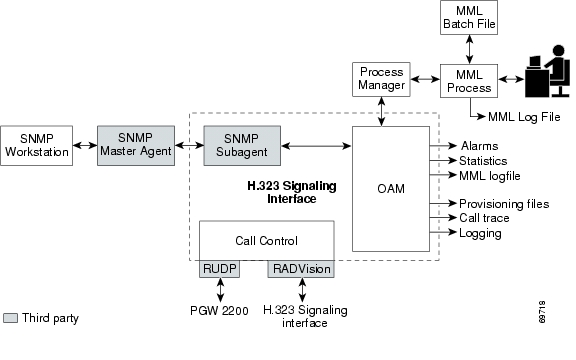
The Cisco HSI system has two subsystems (see Figure 1-2):
•
•
Figure 1-2 Cisco HSI Subsystems
OAM Subsystem
The OAM subsystem provides the following services:
•
•
•
•
•
•
Call Control Subsystem
The call control subsystem provides the following services:
•
•
•
•
•
RUDP
RUDP transports the E-ISUP messages between the PGW 2200 and the Cisco HSI.
RUDP is a Cisco proprietary, connection-oriented, packet-based transport protocol.
RADVision H.323
The Cisco HSI uses the RADVision H.323 stack. The system uses the H.225 (Q.931 and registration, admission, and status [RAS] protocol) and H.245 protocols to implement the H.323 endpoint signaling function.
RADVision H.323 enables the creation of real-time voice H.323 calls over IP networks.
E-ISUP
E-ISUP is a proprietary Cisco protocol based on ISUP. E-ISUP is used for inter-PGW 2200 call control. E-ISUP uses a subset of ISUP messages. The main differences between ISUP and E-ISUP are as follows:
•
•
•
The Cisco HSI provides a conversion between the E-ISUP call control protocol originating from the PGW 2200 and the H.323 call control protocol originating from the IP network (see Figure 1-1).
New Features Introduced in HSI Release 2.21
The following four features are introduced in Cisci HSI, Release 2.21.
Asymmetric Codec Treatment
The Asymmetric Codec Treatment feature averts the potential for inconsistencies in codec selection, which might otherwise result when endpoints attempt to use different codecs for the transmission path.
Empty Capability Set
Empty Capability Set support enables the HSI to close opened logical channels, without releasing the call. Subsequently, the HSI can open a new logical channel, potentially to a different endpoint, or use a different codec.
H.323 Hairpin
The H.323 Hairpin feature can be used to connect a call between two H.323 endpoints without using resources on the media gateway. For example, the PGW can respond to the dialled number in an incoming H.323 call by routing the call to another HSI (perhaps the same HSI) rather than routing the call to the PSTN. In this case, the originating and terminating HSIs establish the call normally but pass the H.245 address of the H.323 endpoints. This enables the two endpoints to use H.245 to negotiate media channels with each other directly, independent of the HSI.
T38 Fax
The T.38 Fax feature enables the HSI to alter a call, initially established for voice, to support a fax transmission.
When a fax call is initiated, a voice call is established. When the terminating gateway detects the fax tone generated by the terminating fax machine, the gateway initiates a T.38 mode request using H.245 procedures from the terminating gateway. If the opposite end of the call acknowledges the T.38 mode request, the initial audio channel is closed and a T.38 fax relay channel is opened.
Operational Environment
This section provides operational environment requirements for the Cisco HSI.
Hardware Requirements
The Cisco HSI is targeted to run on a Sun Netra T1 100/105 platform with an 18-GB hard disk drive, a Sun Netra 120 platform with a 36-GB hard disk drive, or a Sun Fire V120 platform with a 36-GB hard disk drive. These platforms run on the Sun Solaris 8 operating system.
Software Requirements
The Sun Netra T1 100/105platform, Sun Netra 120 platform, and Sun Fire V120 platform run on the Solaris 8 operating system.
Security
The application does not directly provide security features. All security must be implemented at the UNIX level.
Cisco HSI Recovery
The Cisco HSI automatically restarts the main application process if that process terminates.
Cisco HSI System Limitations
The Cisco HSI does not implement security features.
![]()
![]()
![]()
![]()
![]()
![]()
![]()
![]()
Posted: Wed Feb 7 11:59:32 PST 2007
All contents are Copyright © 1992--2007 Cisco Systems, Inc. All rights reserved.
Important Notices and Privacy Statement.