cc/td/doc/product/access/sc/rel7/soln/voip13
hometocprevnextglossaryfeedbacksearchhelp
PDF

Table Of Contents

Provisioning the Cisco SS7 Interconnect for Voice Gateways Solution by Using VSPT

Provisioning Outline

Provisioning Worksheet

Before You Begin

Adding Ethernet Cards and Interfaces

Provisioning SS7 Signaling Routes

Adding the Origination Point Code

Adding the Destination Point Code

Adding the Adjacent Point Codes

Adding Linksets

Adding C7 IP Links to Cisco SLTs

Adding the SS7 Subsystem

Adding SS7 Signaling Services

Adding SS7 Routes

Provisioning NAS Links

Adding NAS External Nodes

Adding NAS Signaling Services

Adding IP Links

Provisioning Trunks

Adding Trunks

Provisioning the Dial Plan/Number Analysis

Provisioning White and Black List Screening

Sample Scenario

Configuring the B White List

Deploying the Session

Provisioning the Cisco SS7 Interconnect for Voice Gateways Solution by Using VSPT


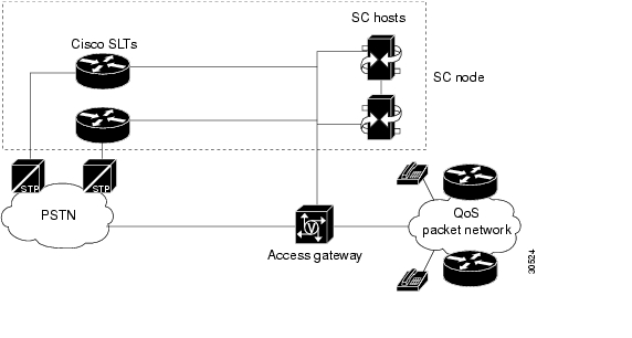
This chapter describes how to provision a sample Cisco SS7 Interconnect for Voice Gateways Solution (see Figure 3-1) using Release 1.6 of the Cisco Voice Services Provisioning Tool (VSPT). The chapter describes a sample configuration for illustration purposes only. Your configuration will vary and depend on your own network configuration.

Release 1.6 of the Cisco VSPT is used with Cisco MGC software Release 7.4(x). You can also use the Cisco Media Gateway Controller Manager (CMM) to provision Cisco MGC software Release 7.3(x) and Release 7.4(x). Refer to the "Provisioning the Cisco SS7 Interconnect for Voice Gateways Solution by Using CMM" chapter for more information on the CMM.

Figure 3-1 Sample Cisco SS7 Interconnect for Voice Gateways Solution


Caution Do not use the sample values in this chapter to provision your system. You must research your network and obtain your own values for the network addresses, point codes, and other parameters used in your solution. If you use the sample values presented here, your configuration will not work.

Provisioning Outline

Perform the following steps to provision the sample Cisco SS7 Interconnect for Voice Gateways Solution.

 
Step
Section and Page

Provision Ethernet cards and interfaces

Step 1

Add the Ethernet cards in the SC host that carry signaling to and from the Cisco SLTs, and add the Ethernet interfaces for the cards in the host.

From the main window, click Interfaces on the left-hand side of the window to expand the hierarchical tree.

Provision SS7 signaling routes

Step 1

Add the OPC1 in your network.

Adding the Origination Point Code

Step 2

Add the DPC2 to identify the destination switch.

Adding the Destination Point Code

Step 3

Add the APCs3 to identify the STPs4 with which the signaling controller communicates signaling information.

Adding the Adjacent Point Codes

Step 4

Add linksets to connect the Cisco SLT5 to the signal transfer points.

Adding Linksets

Step 5

Add C7 IP links for each SS7 link from the signaling controller to the SS7 network (through the Cisco SLT).

Adding C7 IP Links to Cisco SLTs

Step 6

Add the SS7 subsystem to identify the mated STPs.

Adding the SS7 Subsystem

Step 7

Add the SS7 signaling service from the signaling controller to the destination switch.

Adding SS7 Signaling Services

Step 8

Add the SS7 routes for each signaling path from the signaling controller to the destination switch.

Adding SS7 Routes

Provision NAS6 links

Step 1

Add external nodes for the NASs in your network.

Adding NAS External Nodes

Step 2

Add NAS signaling services for each NAS.

Adding NAS Signaling Services

Step 3

Add IP links for each NAS to each Ethernet card in the SC host.

Adding IP Links

Provision trunks

Step 1

Start a trunk provisioning session and add individual trunks from each NAS to the signaling controller.

Adding Trunks

Provision screening:

Step 1

Provision white list screening.

Provisioning White and Black List Screening

Deploy the session.

1 OPC = origination point code

2 DPC = destination point code

3 APCs = adjacent point codes

4 STPs = signal transfer points

5 Cisco SLT = Cisco Signaling Link Terminal

6 NAS = network access server


Note Trunk groups and trunk routing are not used in the Cisco SS7 Interconnect for Voice Gateways Solution. This solution uses nailed trunks between the voice gateways and the PSTN switch. The signaling controller does not perform trunk group selection in this solution.


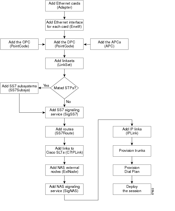
Figure 3-2 shows a flow chart of the provisioning steps discussed in this chapter. After the component, the VSPT name of the component is shown in parenthesis.

Figure 3-2 Provisioning Steps

Provisioning Worksheet

Table 3-1 shows a provisioning worksheet for the sample configuration shown in this chapter.


Note For more information on the individual fields, refer to the Cisco Media Gateway Controller Software Release 7 MML Command Reference Guide.


Table 3-1 Provisioning Worksheet 

Component
Parent Component
MML Name
Description
Parameters

Ethernet card

None

encard1

Ethernet card 1

Card slot: 0

Ethernet card

None

encard2

Ethernet card 2

Card slot: 1

Ethernet interface

encard1

enetif1

Ethernet interface for encard1

None

Ethernet interface

encard2

enetif2

Ethernet interface for encard2

None

OPC

None

opc

Origination point code

Network address: 171.1.4

Network indicator: National Network

DPC

None

dpc1

DPC of PSTN Switch A

Network address: 171.1.3

Network indicator: National Network

APC

None

apc1

APC for STP A

Network address: 171.16.1

Network indicator: National Network

APC

None

apc2

APC for STP B

Network address: 171.16.2

Network indicator: National Network

Linkset

apc1

ls01

Linkset from signaling controller to STP A

Protocol family: SS7-ANSI

Transport type: IP

Linkset

apc2

ls02

Linkset from signaling controller to STP B

Protocol family: SS7-ANSI

Transport type: IP

C7 IP link

ls01

c7iplnk1

Link 1 in Linkset 1

Enet Line Interface: enetif1

Port: 5000

Priority: 1

Peer address: 175.30.241.27

IP address: IPAddr1

SLT slot: 0

SLC: 0

C7 IP link

ls01

c7iplnk2

Link 2 in Linkset 1

Enet Line Interface: enetif1

Port: 5000

Priority: 1

Peer address: 175.30.238.28

IP address: IPAddr2

SLT slot: 0

SLC: 1

C7 IP link

ls02

c7iplnk3

Link 1 in Linkset 2

Enet Line Interface: enetif2

Port: 5000

Priority: 1

Peer address: 175.30.241.27

IP address: IPAddr1

SLT slot: 0

SLC: 0

C7 IP link

ls02

c7iplnk4

Link 2 in Linkset 2

Enet Line Interface: enetif2

Port: 5000

Priority: 1

Peer address: 175.30.238.28

IP address: IPAddr2

SLT slot: 0

SLC: 1

SS7 subsystem

apc1

apc2

subsys1

Route Between STP A and STP B

Adjacent point code: apc1

Mated adjacent point code: apc2

Protocol Family: SS7-ANSI

STP-SCP index: 0

Transport protocol: SCCP

SS7 signaling service

dpc1

ss7sigsvc

SS7 Service to PSTN Switch A

MDO File Name: ANSISS7_STANDARD

Customer Group ID: D123

Customer Group Table: 0101

Side: Network

SS7 route

dpc1

ls01

opc

ss7route1

Route 1 to PSTN Switch A through LS1

Destination PC: dpc1

Linkset: ls01

Originating PC: opc

Priority: 1

SS7 route

dpc1

ls02

opc

ss7route2

Route 2 to PSTN Switch A through LS2

Destination PC: dpc1

Linkset: ls02

Originating PC: opc

Priority: 1

NAS external node

None

nas1

NAS 1

MGCP Domain: nas1

DS1 Type: T1

IP Addr1: 175.30.241.2

NAS external node

None

nas2

NAS 2

MGCP Domain: nas2

DS1 Type: T1

IP Addr1: 175.30.241.3

NAS external node

None

nas3

NAS 3

MGCP Domain: nas3

DS1 Type: T1

IP Addr1: 175.30.241.4

NAS signaling service

nas1

signas1

Signaling service for
NAS 1

MDO file name: BELL_1268_C3

NAS signaling service

nas2

signas2

Signaling service for
NAS 2

MDO file name: BELL_1268_C3

NAS signaling service

nas3

signas3

Signaling service for
NAS 3

MDO file name: BELL_1268_C3


Note The IP links are used for the Redundant Link Manager (RLM), not for carrying call data.


IP link

signas1

signas1-1

IP link for NAS 1 to Ethernet IF 1

Enet line interface: enetif1

Port: 3001

Priority: 1

Peer address: 175.30.241.2

Peer port: 3001

IP address: IPAddr1

Signal slot: 0

Signal port: 0

IP link

signas1

signas1-2

IP link for NAS 1 to Ethernet IF 2

Enet line interface: enetif2

Port: 3001

Priority: 1

Peer address: 175.30.238.2

Peer port: 3001

IP address: IPAddr2

Signal slot: 0

Signal port: 0

IP link

signas2

signas2-1

IP link for NAS 2 to Ethernet IF 1

Enet line interface: enetif1

Port: 3001

Priority: 1

Peer address: 175.30.241.3

Peer port: 3001

IP address: IPAddr1

Signal slot: 0

Signal port: 0

IP link

signas2

signas2-2

IP link for NAS 2 to Ethernet IF 2

Enet line interface: enetif2

Port: 3001

Priority: 1

Peer address: 175.30.238.3

Peer port: 3001

IP address: IPAddr2

Signal slot: 0

Signal port: 0

IP link

signas3

signas3-1

IP link for NAS 3 to Ethernet IF 1

Enet line interface: enetif1

Port: 3001

Priority: 1

Peer address: 175.30.241.4

Peer port: 3001

IP address: IPAddr1

Signal slot: 0

Signal port: 0

IP link

signas3

signas3-2

IP link for NAS 3 to Ethernet IF 2

Enet line interface: enetif2

Port: 3001

Priority: 1

Peer address: 175.30.238.4

Peer port: 3001

IP address: IPAddr2

Signal slot: 0

Signal port: 0


Before You Begin

Log in to the signaling controller and start the VSPT as described in Cisco Media Gateway Controller Software Release 7 Provisioning Guide.


Note Many procedures in this chapter refer to sections in Cisco Media Gateway Controller Software Release 7 Provisioning Guide or the Cisco Media Gateway Controller Software Release 7 Dial Plan Guide. Keep these books handy when performing the procedures in this chapter.


Adding Ethernet Cards and Interfaces

You must add a card component for each card in the signaling controller. For the example in this chapter, you add one Ethernet card for each connection to the IP network—one card for the 10-Mb signaling network and one for the 100-Mb signaling network. These cards permit SS7 signaling between the signaling controller and the Cisco SLTs.

The Ethernet interface provides the physical line interface between the signaling controller's Ethernet card and the physical Ethernet network. You must add an Ethernet interface if you have added an Ethernet card.


Note You must provision the card before provisioning the card interfaces.


Note You provision only one set of cards for one signaling controller (the primary), even though both signaling controllers are highlighted.


To add Ethernet cards and interfaces, perform the following steps:


Step 1 From the main window, click Interfaces on the left-hand side of the window to expand the hierarchical tree.

Step 2 Enter the MML name for the card, encard1, in the Name field.

Step 3 Enter the interface name, enetif1, in the Interface Name field.

Step 4 Select the card slot, 0, from the Card Slot pull-down menu.

Step 5 Click Add. The hierarchical tree on the left of the screen changes to reflect the card you added.

Step 6 Click the name of the interface, enetif1, that is associated with the card you just added.

Step 7 Enter the MML name for the Ethernet interface, enetif1, in the Name field.

Step 8 Enter the description, Ethernet interface for Card 1, in the Description field.

Step 9 Select encard1 from the Card pull-down menu.

Step 10 Click Add.

Step 11 Repeat steps 1 through 10 to add the card and interface for your second Ethernet card (encard2).


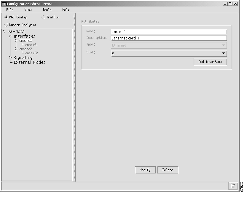
Figure 3-3 gives an example of what the VSPT window looks like after you configure the Ethernet cards and interfaces.

Figure 3-3 Ethernet Cards and Interfaces

Provisioning SS7 Signaling Routes

The SS7 signaling route is the path from the Cisco SC host to a service switching point (SSP) through the Cisco SLTs and signal transfer points (STPs). In the sample configuration in this chapter, the SSP is the PSTN switch. When you provision the SS7 signaling routes, you add the following components:

OPC—Origination point code or the point code of the signaling controller in your network

DPC—Destination point code or the point code of the PSTN switch A to which you are connecting

APCs—Adjacent point codes or the point codes of the adjacent STPs

Linksets

SS7 subsystems (to identify mated STPs)

SS7 routes

SS7 signaling services

For more information on configuring SS7 signaling routes, see Cisco Media Gateway Controller Software Release 7 Provisioning Guide.

Adding the Origination Point Code

A point code is an SS7 network address that identifies an SS7 network node, such as a switch, STP, or SSP.


Note ITU point codes contain 14 bits, and North American point codes contain 24 bits.


Step 1 From the main window, click Signaling on the left-hand side of the window to expand the hierarchical tree.

Step 2 Click Point Codes in the hierarchical tree.

Step 3 Enter the MML name, opc, in the Name field

Step 4 Enter the description, Origination Point Code, in the Description field.

Step 5 Enter the network address, 171.1.4, in the NetAddr field.

Step 6 Select the network indicator, National Network, from the NetIndicator pull-down menu.

Step 7 Click the Add button. The hierarchical tree on the left of the window changes to reflect the originating point code you added.


Adding the Destination Point Code

The following procedure shows how to add the point code for the PSTN switch.


Step 1 Click Point Codes in the hierarchical tree.

Step 2 Enter the MML name, dpc1, in the Name field

Step 3 Enter the description, DPC of PSTN Switch A, in the Description field.

Step 4 Enter the network address, 171.1.3, in the NetAddr field.

Step 5 Select network indicator, National Network, from the NetIndicator pull-down menu.

Step 6 Click the Add button. The hierarchical tree on the left of the window changes to reflect the destination point code you added.


Adding the Adjacent Point Codes

The following procedure shows how to add the adjacent point codes for the STPs.


Note The sample configuration in this chapter uses A-links from the STPs for signaling to the Cisco SLTs. If you have a configuration where F-links come directly from the SSP to the Cisco SLTs, you do not need to add APCs.


Step 1 Click APCs in the hierarchical tree.

Step 2 Enter the MML name, apc1, in the Name field

Step 3 Enter the description, APC for STP A, in the Description field.

Step 4 Enter the network address, 171.16.1, in the NetAddr field.

Step 5 Select the network indicator, National Network, from the NetIndicator pull-down menu.

Step 6 Click Add. The hierarchical tree on the left of the window changes to reflect the APC you added.

Step 7 Repeat steps 1 though 6 to add a second APC, entering apc2 for the name, APC for STP B for the description, and 171.16.2 for the network address.


Adding Linksets

A linkset is a logical set of one or more links originating from an SS7 node (STP) and connecting to an adjacent node. In this example, the linkset contains communication links that join the signaling controller to an adjacent STP.

You must provision one linkset for each connection through the STP to the signaling controller.


Step 1 Click Linksets in the hierarchical tree.

Step 2 Enter the MML name, ls01, in the Name field.

Step 3 Enter the description, Linkset from signaling controller to STP A, in the Description field.

Step 4 Select the apc1 component you provisioned in the "Adding the Adjacent Point Codes" section in the APC pull-down menu.

Step 5 Select SS7-ANSI from the Protocol pull-down menu.

Step 6 Select IP from the Type pull-down menu.

Step 7 Click Add. The hierarchical tree on the left of the window changes to reflect the linkset you added.

Step 8 Repeat steps 1 through 7 to add a linkset from the signaling controller to STPB, choosing the apc2 component and changing the MML name and description accordingly.


Note After creating the linksets, you must create the C7 IP links for each linkset. See "Adding C7 IP Links to Cisco SLTs" section.


Adding C7 IP Links to Cisco SLTs

A C7 IP link component identifies a link between a Cisco SLT's IP address and port and the SS7 network (SSP or STP). The C7 IP link component identifies one of the links within a linkset.


Note Use C7 IP links only when your configuration has Cisco SLTs that carry SS7 signaling to the signaling controller over IP. If your configuration does not include Cisco SLTs and your links from the STPs terminate directly into ITK cards in the signaling controller, you must provision TDM links for the ITK cards. For example, the Cisco SS7 Dial Access Solution Release 2.0 uses ITK cards and TDM links.


You must add a C7 IP link for each physical SS7 link that is connected to the SS7 network through the Cisco SLT. These links correspond to the linksets you created in the "Adding Linksets" section.

Adding Links for Linkset 1

Adding the First Link

You must add two links for linkset 1. To add the first link:


Step 1 Click Signaling, then Linksets. Under Linksets, click Links under the listing for ls01 (a linkset you created in the "Adding Linksets" section).

Step 2 Enter the MML name of the link, c7iplink1, in the Name field.

Step 3 Enter the description, Link 1 in Linkset 1, in the Description field.

Step 4 Select the Ethernet interface, enetif1, from the Interface pull-down menu. (You provisioned the Ethernet interfaces for each Ethernet card in the "From the main window, click Interfaces on the left-hand side of the window to expand the hierarchical tree." section.)

Step 5 Select IP_Addr1 from the IP Addr pull-down menu.


Note The numbered address for this value is found in the XECfgParm.dat file you set up during your initial system configuration. See Cisco Media Gateway Controller Software Release 7 Installation and Configuration Guide for more information.


Step 6 Enter the port number, 5000, in the Port field. This is the UDP port on the signaling controller. You can use any unused UDP port number, but do not use 1 through 1024 (these are reserved for other applications).

Step 7 Select the priority, 1, from the Priority field.


Note To enable loadsharing, use the same priority (1) for each C7 IP link. Traffic is routed equally over the links in case of failure.


Step 8 Enter the IP address of SLT A, 175.30.241.27, in the Peer Address field.


Note You do not need to enter a peer port value because the actual peer port value is found in the *.stPort field in the XECfgParm.dat file you set up during your initial system configuration. See Cisco Media Gateway Controller Software Release 7 Installation and Configuration Guide for more information.


Step 9 Select the signaling link code (SLC), 0, from the SLC pull-down menu. This is the SLC for the line between the Cisco SLT and the STP.

Step 10 Select the physical port on the Cisco SLT, 0, in the Time Slot pull-down menu.


Note The time slot number must be unique for a given link on a particular Cisco SLT. For example, if you have a 2T WAN interface card (WIC) in slot 0 of the Cisco SLT, you can use time slot value 0 or 1 for the first link you provision. The second link on that WIC uses the remaining value.


Step 11 Click Add. The hierarchical tree on the left of the window changes to reflect the C7 IP link you added.


Adding the Second Link

To add the second link:


Step 1 Click Links under the listing for ls01 (a linkset you created in the "Adding Linksets" section).

Step 2 Enter the MML name of the link, c7iplink2, in the Name field.

Step 3 Enter the description, Link 2 in Linkset 1, in the Description field.

Step 4 Select the Ethernet interface, enetif1, from the Interface pull-down menu. (You provisioned the Ethernet interfaces for each Ethernet card in the "From the main window, click Interfaces on the left-hand side of the window to expand the hierarchical tree." section.)

Step 5 Select IP_Addr2 from the IP Addr pull-down menu.


Note The numbered address for this value is found in the XECfgParm.dat file you set up during your initial system configuration. See Cisco Media Gateway Controller Software Release 7 Installation and Configuration Guide for more information.


Step 6 Select the priority, 1, from the Priority field.


Note To enable loadsharing, use the same priority (1) for each C7 IP link. Traffic is routed equally over the links in case of failure.


Step 7 Enter the IP address of SLT B, 175.30.238.28, in the Peer Address field.


Note You do not need to enter a peer port value because the actual peer port value is found in the *.stPort field in the XECfgParm.dat file you set up during your initial system configuration. See Cisco Media Gateway Controller Software Release 7 Installation and Configuration Guide for more information.


Step 8 Select the signaling link code (SLC), 1, from the SLC pull-down menu. This is the SLC for the line between the Cisco SLT and the STP.

Step 9 Select the physical port on the Cisco SLT, 0, in the Time Slot pull-down menu.


Note The time slot number must be unique for a given link on a particular Cisco SLT. For example, if you have a 2T WAN interface card (WIC) in slot 0 of the Cisco SLT, you can use time slot value 0 or 1 for the first link you provision. The second link on that WIC uses the remaining value.


Step 10 Click Add. The hierarchical tree on the left of the window changes to reflect the C7 IP link you added.


Adding Links for Linkset 2

Adding the First Link

You must add two links for linkset 2. To add the first link:


Step 1 Click Links under the listing for ls02 (a linkset you created in the "Adding Linksets" section).

Step 2 Enter the MML name of the link, c7iplink3, in the Name field.

Step 3 Enter the description, Link 1 in Linkset 2, in the Description field.

Step 4 Select the Ethernet interface, enetif2, from the Interface pull-down menu. (You provisioned the Ethernet interfaces for each Ethernet card in the "From the main window, click Interfaces on the left-hand side of the window to expand the hierarchical tree." section.)

Step 5 Select IP_Addr1 from the IP Addr pull-down menu.


Note The numbered address for this value is found in the XECfgParm.dat file you set up during your initial system configuration. See Cisco Media Gateway Controller Software Release 7 Installation and Configuration Guide for more information.


Step 6 Select the priority, 1, from the Priority field.


Note To enable loadsharing, use the same priority (1) for each C7 IP link. Traffic is routed equally over the links in case of failure.


Step 7 Enter the IP address of SLT A, 175.30.241.27, in the Peer Address field.


Note You do not need to enter a peer port value because the actual peer port value is found in the *.stPort field in the XECfgParm.dat file you set up during your initial system configuration. See Cisco Media Gateway Controller Software Release 7 Installation and Configuration Guide for more information.


Step 8 Select the signaling link code (SLC), 0, from the SLC pull-down menu. This is the SLC for the line between the Cisco SLT and the STP.

Step 9 Select the physical port on the Cisco SLT, 0, in the Time Slot pull-down menu.


Note The time slot number must be unique for a given link on a particular Cisco SLT. For example, if you have a 2T WAN interface card (WIC) in slot 0 of the Cisco SLT, you can use time slot value 0 or 1 for the first link you provision. The second link on that WIC uses the remaining value.


Step 10 Click Add. The hierarchical tree on the left of the window changes to reflect the C7 IP link you added.


Adding the Second Link

To add the second link:


Step 1 Click Links under the listing for ls02 (a linkset you created in the "Adding Linksets" section).

Step 2 Enter the MML name of the link, c7iplink4, in the Name field.

Step 3 Enter the description, Link 2 in Linkset 2, in the Description field.

Step 4 Select the Ethernet interface, enetif2, from the Interface pull-down menu. (You provisioned the Ethernet interfaces for each Ethernet card in the "From the main window, click Interfaces on the left-hand side of the window to expand the hierarchical tree." section.)

Step 5 Select IP_Addr2 from the IP Addr pull-down menu.


Note The numbered address for this value is found in the XECfgParm.dat file you set up during your initial system configuration. See Cisco Media Gateway Controller Software Release 7 Installation and Configuration Guide for more information.


Step 6 Select the priority, 1, from the Priority field.


Note To enable loadsharing, use the same priority (1) for each C7 IP link. Traffic is routed equally over the links in case of failure.


Step 7 Enter the IP address of SLT B, 175.30.238.28, in the Peer Address field.


Note You do not need to enter a peer port value because the actual peer port value is found in the *.stPort field in the XECfgParm.dat file you set up during your initial system configuration. See Cisco Media Gateway Controller Software Release 7 Installation and Configuration Guide for more information.


Step 8 Select the signaling link code (SLC), 1, from the SLC pull-down menu. This is the SLC for the line between the Cisco SLT and the STP.

Step 9 Select the physical port on the Cisco SLT, 0, in the Time Slot pull-down menu.


Note The time slot number must be unique for a given link on a particular Cisco SLT. For example, if you have a 2T WAN interface card (WIC) in slot 0 of the Cisco SLT, you can use time slot value 0 or 1 for the first link you provision. The second link on that WIC uses the remaining value.


Step 10 Click Add. The hierarchical tree on the left of the window changes to reflect the C7 IP link you added.


Adding the SS7 Subsystem

You must add an SS7 subsystem that identifies each pair of mated STPs. This allows the signaling controller to route traffic over the C-links in case of a failure between one of the STPs and an endpoint.


Note Adding an SS7 subsystem is optional. The SS7 subsystem is added in this instance because the associated PSTN switch in the example uses a mated pair of STPs.


Step 1 Click Mated Pairs in the hierarchical tree.

Step 2 Enter the MML name, subsys1, in the Name field.

Step 3 Enter the description, Route Between STP A and STP B, in the Description field.

Step 4 Select the apc1 component you provisioned in the "Adding the Adjacent Point Codes" section in the APC pull-down menu.

Step 5 Select the apc2 component you provisioned in the "Adding the Adjacent Point Codes" section in the Mated APC pull-down menu.

Step 6 Select the priority for the mated pair, 3, from the Priority pull-down menu.


Tip The priority for the SS7 subsystem should always be lower than the priority for the C7 IP links between the signaling controller and the STPs (which you provision in the "Adding C7 IP Links to Cisco SLTs" section). You do not want signaling traffic on the C-links, because they are used only if the F-links go down. If the priority for the C-links (SS7 subsystem) is higher than or equal to the priority for the C7 IP links, the signaling controller routes signaling traffic over those links. If you set the SS7 subsystem priority lower than the priority for the C7 IP links, the signaling controller routes traffic over the C-links between the STPs only if the links with a higher priority are not available.


Step 7 Enter the subsystem number, 0, in the Subsystem Number field. This value is not used when you are identifying mated STPs.

Step 8 Enter 0 in the STP/SCP Index field. This value is not used when you are identifying mated STPs.

Step 9 Select SCCP from the Transport Protocol pull-down menu.

Step 10 Select SS7-ANSI from the Protocol Family pull-down menu.

Step 11 Click Add. The hierarchical tree on the left of the screen changes to reflect the mated pair you added.


Adding SS7 Signaling Services

The SS7 signaling service specifies the path and the protocol variant that the signaling controller uses to communicate with a remote switch (SSP) that is sending bearer traffic to the NASs.

You must add an SS7 signaling service from the signaling controller to the PSTN switch.


Step 1 Click SS7 Paths in the hierarchical tree.

Step 2 Enter the MML name, ss7sigsvc, in the Name field.

Step 3 Enter the description, SS7 Service to PSTN Switch A, in the Description field.

Step 4 Select the DPC, dpc1, (you provisioned dpc1 as your destination point code for the PSTN switch in the "Adding the Destination Point Code" section) from the Pointcode pull-down menu.

Step 5 Select the side, network, from the Side pull-down menu.

Step 6 Select ANSISS7_STANDARD as the protocol for this signaling service from the MDO pull-down menu.

Step 7 Enter the customer group ID, D123, in the Customer Group ID field. This is the name of the dial plan file you use for screening. See "Provisioning White and Black List Screening" section.


Note We recommend that you go ahead and provision a customer group ID for your SS7 signaling service, even if you are not planning on currently using the screening tools. This is because once the SS7 signaling service is placed in service, you would have to take it out-of-service to add a customer group ID.


Step 8 Enter the customer group table, 0101, in the Customer Group Table field. This is the name of the dial plan table you use for screening. See "Provisioning White and Black List Screening" section.

Step 9 Click the Add button. The hierarchical tree on the left of the screen changes to reflect the SS7 path you have added.

Step 10 After you create the signaling service, click the Properties button to modify SS7 signaling service properties that are required for the screening process.

Step 11 Select ReleaseMode from the Name pull-down menu.

Step 12 Enter Sync in the Value field.

Step 13 If you are going to provision a dial plan, proceed to Step 14. Otherwise, proceed to Step 20.

Step 14 Select BOrigStartIndex from the Name pull-down menu.

Step 15 Enter 1 in the Value field.

Step 16 Click Modify to modify the value of the property.

Step 17 Select BTermStartIndex from the Name pull-down menu.

Step 18 Enter 2 in the Value field.

Step 19 Click Modify to modify the value of the property.

Step 20 Click OK to save the modified property values.


Adding SS7 Routes

An SS7 route is a path through a linkset between the signaling controller and another signaling controller or TDM switch. In this example, the SS7 routes indicate the linksets that carry SS7 signals between the signaling controller and the PSTN switch A.

You must add an SS7 route for each signaling path from the signaling controller to the PSTN switch A. You provision a route for each linkset.


Step 1 Click SS7 Routes in the hierarchical tree.

Step 2 Enter the MML name, ss7route1, in the Name field.

Step 3 Enter the description, Route 1 to PSTN Switch A through LS1, in the Description field.

Step 4 Select opc (the OPC for the signaling controller that you added in the "Adding the Origination Point Code" section) from the Originating PC pull-down menu.

Step 5 Select dpc1 (the DPC for PSTN Switch A that you provisioned in the "Adding the Destination Point Code" section) from the Destination PC pull-down menu.

Step 6 Select ls01 from the Linkset pull-down menu.

Step 7 Enter the priority for this route, 1, in the Priority field.


Note Routes can share signaling traffic. You can set loadsharing by making the priorities the same for all routes.


Step 8 Click the Add button. The hierarchical tree on the left of the window changes to reflect the SS7 route you added.

Step 9 Repeat steps 1 through 8 to add another route using linkset 2, changing the MML name and description, and selecting ls02 as the linkset.


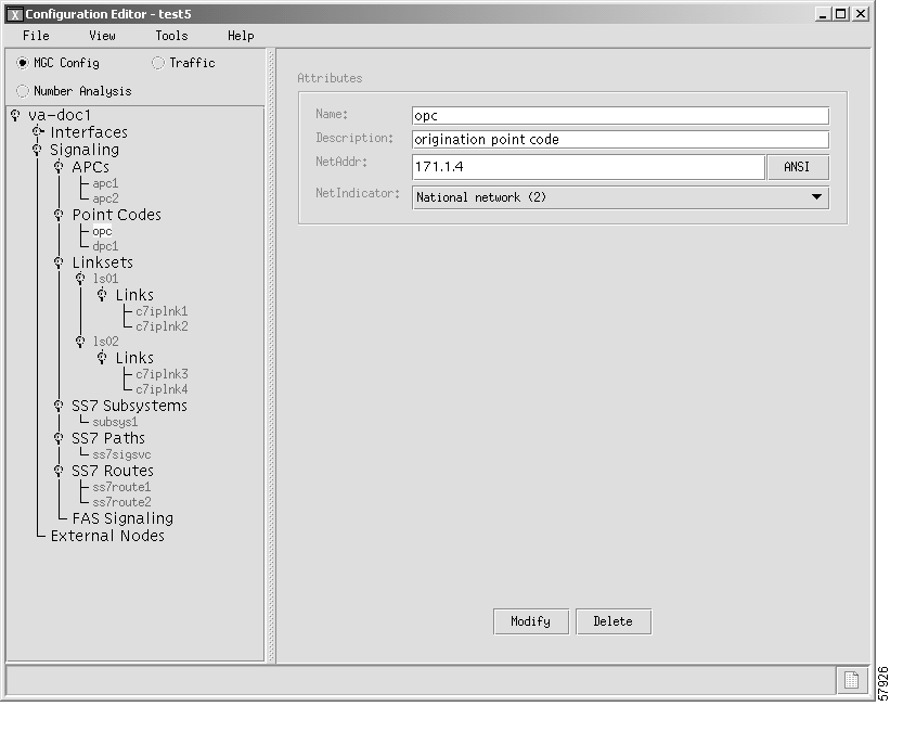
Figure 3-4 provides an example of the VSPT window after you have provisioned SS7 signaling route data.

Figure 3-4 SS7 Signaling Route Data

Provisioning NAS Links

NAS links indicate the communication path the signaling controller uses to control the bearer traffic that passes through each NAS.

To add links to the NASs in your network, you must add the following components:

NAS external node

NAS signaling service

IP links

Adding NAS External Nodes

You must add a NAS external node for each voice gateway in your network.


Step 1 From the left-hand side of the main window, click External Nodes.

Step 2 Enter the MML name of the NAS, nas1, in the Name field.

Step 3 Enter the description, NAS 1, in the Description field.

Step 4 Select the type of NAS, AS5300, from the Type pull-down menu.

Step 5 Click Add.

Step 6 Repeat steps 1 through 5 for nas2 and nas3.

Step 7 Click nas1 to view the attributes for this NAS on the right side of the window. The hierarchical tree on the left-hand side of the window changes to reflect the addition of an external node (that is, nas1).

Step 8 Verify that nas1 is present in the Name field.

Step 9 Verify that NAS 1 is present in the Description field.

Step 10 Verify that AS5300 is present in the Type field.

Step 11 Verify that nas1 appears in the MGCP Domain field. This value should always match the value in the Name field.

Step 12 Select T1 from the DS1 Type pull-down menu.

Step 13 Enter 175.30.241.2 in the IP Addr1 field and 255.255.255.0 in the IP Subnet Mask1 field. These addresses/subnet mask values must match the values configured on the NAS. It represents the interface used for primary IP connectivity.


Note If used, the IP Addr2 addresses/subnet mask fields must match the secondary IP address values configured on the NAS.


Note The other fields in this window are not used for NASs.


Step 14 Click Modify to save the changes.

Step 15 Repeat steps 7 through 14 for each NAS, using 175.30.241.3 as the IP address for nas2 and 175.30.241.4 as the IP address for nas3.


Adding NAS Signaling Services

The procedure in this section shows you how to add a NAS signaling service for each NAS you created in the "Adding NAS External Nodes" section. The NAS signaling service indicates the Q.931 protocol path between the signaling controller and the NASs.


Note It is possible for more than one NAS to use a single NAS signaling service, as long as each NAS is associated with the same DPC.


Step 1 Click on NAS, below the nas1 component. The window displays the NAS signaling service fields.

Step 2 Enter the MML name for the NAS signaling service, signas1, in the Name field.

Step 3 Enter the description, Signaling service for NAS1, in the Description field.

Step 4 Select the protocol, BELL_1268_C3 from the MDO pull-down menu.

Step 5 Click Add to add this NAS signaling service.

Step 6 Repeat steps 1 through 5 for each NAS, changing the MML names and descriptions accordingly.


Adding IP Links

You must add an IP link from each NAS to each Ethernet card and interface in the signaling controller. In this example, you provision the following IP links:

NAS 1 to enetif1

NAS 1 to enetif2

NAS 2 to enetif1

NAS 2 to enetif2

NAS 3 to enetif1

NAS 3 to enetif 2


Note If you are provisioning two links from the signaling controller to the same NAS, you need two different Ethernet IP addresses on both the signaling controller and the NAS.


Step 1 Click Links below the signas1 component. You can see that VSPT has already added a link, signas1-1, the individual IP link created for this signaling service.

Step 2 Click signas1-1. The window displays the fields associated with this IP link.

Step 3 Enter the description, IP link for NAS1 to Ethernet IF 1, in the Description field.

Step 4 Select the Ethernet interface, enetif1, from the Interface pull-down menu. (You provisioned the Ethernet interfaces for each Ethernet card in the "From the main window, click Interfaces on the left-hand side of the window to expand the hierarchical tree." section.)

Step 5 Select IPAddr1 from the IP Addr pull-down menu.


Note The numbered address for this value is found in the XECfgParm.dat file you set up during your initial system configuration. See Cisco Media Gateway Controller Software Release 7 Installation and Configuration Guide for more information.


Step 6 Enter the port number, 3001, in the Port field. This is the UDP port on the signaling controller. You can use any unused UDP port number, but do not use 1 through 1024 (these are reserved for other applications).

Step 7 Select the priority, 1, from the Priority pull-down menu.


Note To enable loadsharing, use the same priority (1) for each IP link. Traffic is routed equally over the links in case of failure.


Step 8 Enter the IP address of nas1, 175.30.241.2, in the Peer Address field.

Step 9 Enter the port number, 3001, in the Peer Port field. This is the port on the signaling controller.

Step 10 Click Add.

Step 11 Repeat steps 1 through 10 to add the second IP link from NAS 1 to enetif2, changing the MML name, Ethernet interface, and peer address accordingly.

Step 12 Repeat the steps 1 through 11 to add two links from each remaining NAS to the signaling controller, selecting the appropriate IP signaling service and changing the MML name, description, and peer address accordingly.


Note The provisioning example in this section creates two redundant link manager (RLM) links (forming an RLM group) for each NAS. As of Release 7.4(12) of the Cisco MGC software, you can create multiple RLM groups for each NAS. To create multiple RLM groups for each NAS, repeat steps 1 through 11 for each link in each RLM group. Ensure that the IP links in any multiple RLM groups use the following values defined in the associated NAS: the IP address of the loopback interfaces as the peer address value and the port number of the loopback interfaces as the peer port value.


Figure 3-5 illustrates the appearance of the VSPT window after you have provisioned external nodes.

Figure 3-5 NAS Links Provisioned
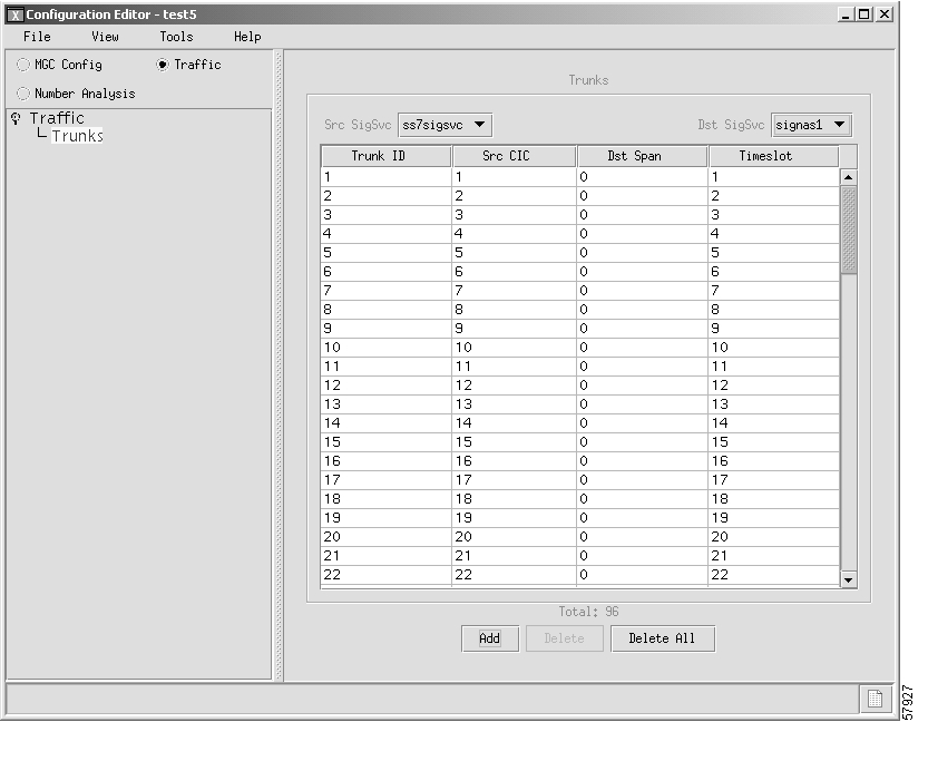
Provisioning Trunks

You must add trunks for each connection between the NAS and the PSTN switch. NAS 1 has four T1 lines, NAS 2 has four T1 lines, and NAS 3 has three T1 lines. Each T1 contains 24 trunks, or DS0s. For the examples in this section, you must provision 264 trunks (96 for NAS1, 96 for NAS2, and 72 for NAS3).


Note If you have already provisioned the spans on the NAS to be associated with these trunks, you must remove these spans from service on the NAS using the shutdown command, before you provision the trunks on the Cisco SC2200.


Adding Trunks


Note The values used for the destination span ID in the following examples are sample values. The real values for this parameter would match whichever PRI port the T1 is connected to on the NAS. Valid values are 0 through 3.


To add trunks, perform the following steps:


Step 1 Click the Traffic radio button the top of the left panel, click the Trunks component and then highlight the Traffic component type. The DAS Confirm dialog box opens, which asks you if this configuration is for a Dial Access Solution.

Step 2 Click Yes in the DAS Confirm dialog box. The Trunk Groups and Routing component types are removed from the left Traffic panel. Only Trunks remain.

Step 3 Highlight Trunks in the left panel. A corresponding properties panel appears on the right side of the window.

Step 4 Click Add to add trunks. The right panel displays fields associated with trunks.

Step 5 Select the signaling service, ss7sigsvc, from the Source Signaling Service pull-down menu. (You created this signaling service in the "Adding SS7 Signaling Services" section.)

Step 6 Select the NAS signaling service, signas1, from the Destination Signaling Service pull-down menu. (You created this service in the "Adding NAS Signaling Services" section.)

Step 7 Select T1 from the DS1 Type pull-down menu. This indicates you are using the North American T1 facility.

Step 8 Enter a trunk ID, 1, in the First Trunk ID field.


Note Each trunk ID must be a unique number. This number is used by the Cisco MGC for tracking.


Step 9 Enter the first CIC number for this trunk, 1, in the First Source CIC field.


Note This value must match the number of the CIC you are connecting to on the far-end.


Step 10 Enter the first destination span for this trunk, 0, in the First Destination Span field.


Note This value is the controller on the media gateway that are used by these trunks.


Step 11 Enter the first timeslot for this trunk, 1, in the First Timeslot field.

Step 12 Enter the number of trunks you want to add, 24, in the Number of Trunks to Add field.

Step 13 Click Finish to add the trunks. The properties panel updates to display a table of the 24 trunks you just created on Span 0.


After creating the trunks for the first T1, you must repeat the process to add trunks for the second, third, and fourth T1 that are connected to NAS1:


Step 1 To add 24 more trunks for the span 1 going to nas1, click on Add. The properties panel now displays the previous properties where you can indicate the Source and Destination signaling services.

Step 2 Enter a trunk ID, 25, in the First Trunk ID field.

Step 3 Enter the first CIC number for this trunk, 25, in the First Source CIC field.

Step 4 Enter the number of trunks you want to add, 24, in the Number of Trunks to Add field.

Step 5 Click Finish to add the trunks. The properties panel updates to display a table of the 24 trunks you just created on Span 1.


The system creates 24 trunks for this T1, automatically incrementing the Trunk ID each time.

Add the trunks for the third T1:


Step 1 To add 24 more trunks for the span 2 going to nas1, click on Add. The properties panel now displays the previous properties where you can indicate the Source and Destination signaling services.

Step 2 Enter a trunk ID, 49, in the First Trunk ID field.

Step 3 Enter the first CIC number for this trunk, 49, in the First Source CIC field.

Step 4 Enter the number of trunks you want to add, 24, in the Number of Trunks to Add field.

Step 5 Click Finish to add the trunks. The properties panel updates to display a table of the 24 trunks you just created on Span 2.


The system creates 24 trunks for this T1, automatically incrementing the Trunk ID each time.

Add the trunks for the fourth T1:


Step 1 To add 24 more trunks for the span 3 going to nas1, click on Add. The properties panel now displays the previous properties where you can indicate the Source and Destination signaling services.

Step 2 Enter a trunk ID, 73, in the First Trunk ID field.

Step 3 Enter the first CIC number for this trunk, 73, in the First Source CIC field.

Step 4 Enter the number of trunks you want to add, 24, in the Number of Trunks to Add field.

Step 5 Click Finish to add the trunks. The properties panel updates to display a table of the 24 trunks you just created on Span 3.


The system creates 24 trunks for this T1, automatically incrementing the Trunk ID.

After you have created trunks for the four T1s that terminate at NAS1, you must add trunks for the four T1s that terminate at NAS2 and the three T1s that terminate at NAS3. Follow the previous instructions but make the changes outlined in Table 3-2 and Table 3-3.

Table 3-2 NAS2 Trunks

Field
Span 1 Value
Span 2 Value
Span 3 Value
Span 4 Value

First Trunk ID

97

121

145

169

Source CIC

97

121

145

169


Table 3-3 NAS3 Trunks

Field
Span 1 Value
Span 2 Value
Span 3 Value

Trunk ID

193

217

241

Source Time Slot/CIC

193

217

241


Figure 3-6 provides an example of the VSPT window after trunks are provisioned.

Figure 3-6 Trunk Data


Note If you have already provisioned the spans on the NAS to be associated with these trunks, you can now return those spans to service on the NAS using the no shutdown command.


Provisioning the Dial Plan/Number Analysis

The signaling controller provides the ability to create a dial plan to perform number analysis on both the A (calling) number and B (called) number. You can set up dial plans to perform routing, send calls to announcement servers, modify dialed digits, and perform other results.

You do not use the advanced features in the dial plan for the Cisco SS7 Interconnect for Access Servers Solution and the Cisco SS7 Interconnect for Voice Gateways Solution. In these solutions, the signaling controller routes calls directly over the IP network and does not perform routing or switching to
trunk groups.

Provisioning White and Black List Screening

In the Cisco SS7 Interconnect for Access Servers Solution, you might want to perform white and black list screening to include or exclude calls from certain numbers. You can provision white lists that specify allowed A-numbers (calling numbers) or B-numbers (called numbers). Black lists block specified A-numbers (calling numbers) or B-numbers (called numbers).

The VSPT allows you to enter numbers that are collected in a batch file. When you set the white or black list file and the file is post-processed, the commands in the file are applied to the black and white list databases. For example, if you added numbers to the white list, the numbers are inserted into the database when the file is post-processed.


Note Because the VSPT white and black list provisioning is done by batch file, adding or removing a row during the provisioning session does not mean the row has been added to or removed from the database.


Sample Scenario

This section provides procedures for provisioning a sample B white list. In this scenario, assume that a company offering dialup service has two telephone numbers: one for regular customers and one for reduced-rate customers. Regular customers call (703) 484-3000 for dialup service. Reduced-rate customers call (703) 484-6000 and receive discount rates; for example, they could pay a monthly fee in exchange for cheaper per-minute charges. So the company wants to analyze calls made to (703) 484-6000 and route calls to the IP network only if they are from reduced-rate customers, or those customers on the white list. The SC host uses a dial plan result of screening to screen the A-number to see if the call is permitted.

Configuring the B White List

To configure a B white list, perform the steps in the following sections:

"Setting Number Analysis Properties" section

"Creating the Dial Plan File" section

"Setting the Screening Data" section

"Adding Calling Numbers to the B-Number White List File" section

"Setting the Service Name" section

"Adding the Screening Result Set and Result" section

"Adding the Called Number" section

These events occur during the screening:

1. Calls are made to (703) 484-6000.

2. The SC host receives a call and performs analysis based on the called number.

3. As a result of analysis, the SC host sees that calls directed to that number must be screened for the calling party number (A-number).

4. The SC host checks the A-number against the B white list to see if the calling party is authorized.

5. If the calling party does appear in the B white list database, the call is put through.

6. If the calling party does not appear in the B white list database, the call is disconnected.

Setting Number Analysis Properties

Before you set up the screening, make sure you have set number analysis properties for your SS7 signaling services. You set these properties in "Adding SS7 Signaling Services" section. These values are:

BOrigStartIndex: 1

BTermStartIndex: 2

CustomerGroupID: D123

Creating the Dial Plan File

Perform the following steps to create the dial plan file:


Step 1 From the main provisioning window, click the Number Analysis button.

Step 2 In the left-hand pane of the main provisioning window, click Number Analysis.

Step 3 Enter the customer group ID, D123, in the Customer Group ID field.

Step 4 Click the Add button. The customer group ID you entered appears underneath the Number Analysis component.


Setting the Screening Data

Perform the following steps to create the white list file:


Step 1 To display the call screening window, click the D123, Results, and Screening components on the left-hand side of the window.

Step 2 Select BWHITE from the File Type pull-down menu.

Step 3 Enter the file name, D123.bwhite, in the File name field.

Step 4 Click the Add button. The Screening file is added to the hierarchical tree on the left-hand side of the window.


Adding Calling Numbers to the B-Number White List File

Perform the following steps to add A-numbers to the B-number white list:


Step 1 Click the BWHITE component below the Screening component on the left-hand side of the window.

Step 2 Click the Edit File button to edit the D123.bwhite file. A dialog box opens asking you if want to create the D123.bwhite file.

Step 3 Click Yes and a text file editor window displays.

Step 4 Click on the Edit menu and select Add new numbers to add calling numbers to the text file. A dialog box is displayed.

Step 5 Enter calling numbers into the New Numbers field. Each number is separated by a comma, without a space.

For example, three calling numbers would be entered in the following format:

The first line of your file should entered as follows:

7035552222,7035551245,7035554567

Step 6 Enter the service name, onerate, in the Service Name field.

Step 7 Click OK once you have finished entering data for the calling numbers. The data for the calling numbers is added to the file.

Step 8 Save and exit from the text file editor.


Setting the Service Name

To set up the service name, perform the following steps:


Step 1 To display the service name window, click the Service component underneath the Results component on the left-hand side of the window.

Step 2 Click the Add button. A dialog box is displayed.

Step 3 Enter the service name, onerate, in the Service Name field.

Step 4 Click OK to save the service name.


Adding the Screening Result Set and Result

Perform the following steps to add a result set and result of screening:


Step 1 To display the result set window, click the Resultset component underneath the Results component on the left-hand side of the window.

Step 2 Click the Add button. The Add Result Set dialog box is displayed.

Step 3 Enter 1ratescreen in the Result Set Name field and click OK. The result name is added to the window.

Step 4 To define the result type that you want the dialed digits to produce during number analysis, select the 1ratescreen result set you just added and click the Add button at the bottom of the window. A dialog box is displayed.

Step 5 Enter the name of the result, 1ratescreen, in the Result Name field.

Step 6 Select the result type, SCREENING, from the Result Type pull-down menu. The fields at the bottom of the window change to reflect the data necessary for screening.

Step 7 Ensure that the value in the Screen type pull-down menu is 1 (for white list screening).

Step 8 Select the service name, onerate, from the Service name pull-down menu.

Step 9 Click OK. The dialog box closes.


Adding the Called Number

Perform the following steps to add the called number to the database:


Step 1 Click the Triggers and the Bdigtree components on the left-hand side of the window to display the B digit tree window.

Step 2 Click the Add button. The Add Bdigtree dialog box is displayed.

Step 3 Enter 7034846000 in the Digit String field.

Step 4 Ensure that the Call side pull-down menu is set to originating.

Step 5 Select 1ratescreen in the Result Set pull-down menu.

Step 6 Click OK. The dialog box closes and the information for the called number is added to the window.


Figure 3-7 provides an example of the VSPT window after a dial plan has been provisioned.

Figure 3-7 Dial Plan Data

Deploying the Session

The example used in this chapter features a continuous-service SC node. You must deploy the session to save it to the machine you are provisioning. The system then copies the files to the standby SC node.

To deploy the session:


Step 1 From the Tools menu, select Deploy. A dialog box is displayed.

Step 2 Enter the configuration name on the destination Cisco MGC.

You can click VSC View to browse the target Cisco MGC. This lets you avoid duplicating a configuration name that already exists on your Cisco MGC.

Step 3 Indicate how you want to deploy the configuration:

If you want to send the configuration to the Cisco MGC but not activate it, click the button next to Send Configuration to VSC Only.

If you want to send the configuration to the Cisco MGC and activate it, click the button next to Send and Activate Configuration.

If you have a continuous-service configuration with two Cisco MGC hosts, click the button next to Send, Activate and Synchronize failover. The configuration is saved on the active host and copied to the standby host. You must restart the standby server after deployment to apply changes.


Note Do not select the Do not deploy to VSC box. This option is not used in Cisco SS7 Interconnect to Access Servers or Voice Gateways solutions.


Step 4 Click OK.


Note Even though the Cisco MGC supports only one provisioning session at one time, multiple user provisioning is supported in VSPT version 1.6. If more than one user is provisioning, and a deploy is attempted, the deploy is placed on hold for a 45 second timeout interval. Up to three retries can be attempted before the deploy attempt fails.


hometocprevnextglossaryfeedbacksearchhelp

Posted: Wed Oct 20 10:41:16 PDT 2004
All contents are Copyright © 1992--2004 Cisco Systems, Inc. All rights reserved.
Important Notices and Privacy Statement.