|
|

This chapter briefly describes the various Cisco SS7 Interconnect for Voice Gateways Solution configuration options and the required and optional components:
The Cisco SS7 Interconnect for Voice Gateways Solution provides the following configuration options:
You can deploy the Cisco SS7 Interconnect for Voice Gateways Solution in one of the following configurations:
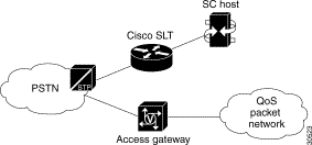
A simplex configuration is an SC zone that consists of a single SC host operating with one or more Cisco SLTs. The SC application is run on the SC host and the SS7 signaling links are terminated on the Cisco SLT. An IP control LAN is used to interconnect the host server with the Cisco SLTs. One or more access gateways are required for bearer channel termination. See Figure 2-1.
Quality of Service (QoS) packet network in Figure 2-1 refers to a packet network in which both bandwidth control and latency control are achieved for the particular application.
 |
Note Simplex configurations provide no fault tolerance and are typically used for solution testing or validation or noncritical installations. If the host fails, calls are dropped, and service is discontinued. |
A continuous service configuration is an SC zone that consists of a pair of SC hosts running in an active (primary) and standby (secondary) mode, operating with one or more access gateways and one or more Cisco SLTs. An error-checking function runs continuously between the two SC hosts, monitoring the primary SC host. When the function detects an error condition on the primary SC host, responsibility for call processing is switched to the secondary SC host. The secondary SC host now becomes the active SC host; call preservation is maintained.
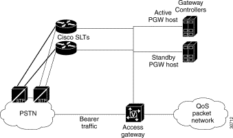
Figure 2-2 shows an example of a continuous service configuration with redundant signaling links terminating on a pair of Cisco SLTs with bearer traffic terminating on the access gateway.
The Cisco SS7 Interconnect for Voice Gateways Solution performs functions to exchange telephone control messages between the following components that support the end user's signaling network connection:
Cisco Signaling Controller—Provides a signaling protocol conversion and network Q.931 call control to communicate with the access gateways. One signaling controller might provide signaling and call-processing services for multiple access gateways in geographically distributed locations, over redundant IP links used for ISDN signaling.
Cisco SLT—Handles the incoming and outgoing SS7 messages (MTP layer 1 and 2) from the A-links (access links) connected to Signal Transfer Points (STPs) or F-links connected to Service Switching Points (SSPs). Also, when used in Drop and Insert mode, the Cisco SLT grooms off the terminating signaling link from F-links (fully associated links) and then hairpins the bearer channels (ISUP) to the access gateway.
Cisco Access Gateway—Provides termination for PSTN trunks. An access gateway functions as a server to the SS7 bearer links. The access gateway has at least two IP network interfaces: one to carry IP packet data onto one or more of the Internet Service Provider's (ISP's) backbones and another to connect to the ISP's secure management, signaling, and Q.931 control network.
Your Cisco SS7 Interconnect for Voice Gateways Solution can be deployed in three ways, as described in "Simplex and Redundancy Options", with the following SS7 signaling network connections.
 |
Note Type of connection would depend on your specific network requirements. |
An A-link with Cisco SLT signaling connection is an access link from the PSTN Signal Transfer Point (STP) connected to the Cisco SLT of the SC node, through EIA/TIA-449, EIA/TIA-530, V.35, and T1/E1 interfaces. This option can be used with simplex and continuous service host configurations. Each interface supports a single signaling channel.
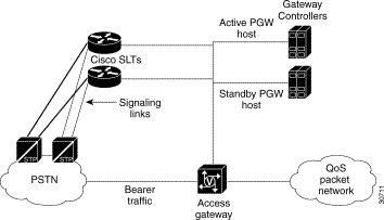
In the A-link SLT signaling connection, the Cisco SLT processes the two lowest-level SS7 signaling protocols, MTP1 and MTP2. The upper layer protocols are then forwarded to the SC host over the control signaling network. Each Cisco SLT supports two signaling network connections. Multiple Cisco SLTs can be used to support additional signaling channels or provide redundant signal paths between the signaling network and the control signaling network, as illustrated in Figure 2-3.
An F-link with Cisco SLT signaling connection is a fully associated link from the SS7 network to the Cisco SLT of the SC node. F-links connect the SC host directly to a Service Switching Point (SSP) or a Service Control Point (SCP) in the SS7 network; they do not make an intermediate connection through STPs.
The F-link SLT signaling configuration supports EIA/TIA-449, EIA/TIA-530, V.35, and T1/E1 interfaces that are installed in the Cisco SLT. The F-link SLT configuration can be used with simplex and continuous service SC host configurations. Each interface supports a single DS0 signaling channel.
An A-link or F-link with Cisco SLT (Drop and Insert) signaling connection is similar, respectively, to an A-link or F-link SLT signaling connection. Fully associated links directly connect an SSP or SCP to the Cisco SLT. The difference is that the A-link and F-link Drop and Insert configurations support a single DS0 signaling channel per link and additional bearer traffic channels up to the capacity of the T1 or E1 link as shown in Figure 2-4.
 |
Note The F-link Drop and Insert technique is also known as time-division multiplexing (TDM) cross-connect. |
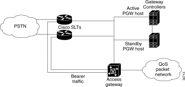
The F-link drop and insert signaling configuration supports T1 and E1 interfaces using signaling interface cards installed in the Cisco SLT. The Drop and Insert cards are special two-port cards designed for this application. Signal and bearer traffic enter one port together, then the Cisco SLT separates the bearer traffic and routes it out the second port.
The F-link Drop and Insert configuration can be used with simplex and continuous service host configurations. Each interface card supports a single DS0 signaling channel.
Designing your network to handle control signaling is a complex and sophisticated task beyond the scope of this document. This section briefly describes what control signaling network options are available and some network engineering guidelines to consider.
Your control network consists of a number of hubs, switches, or routers configured together to support the number of ports in your point of presence (POP), the traffic characteristics of incoming calls, the geographic location of the Cisco SS7 Interconnect for Voice Gateways Solution components, and the level of redundancy that you require. Other factors to consider are:
Control traffic (signaling) should be segregated from the bearer data IP traffic (towards the internet/intranet) onto a different network. This optimizes control traffic latency and provides added security. Redundancy in your control network can be provided by duplicating your Cisco SS7 Interconnect for Voice Gateways Solution components. In the event that the control network fails or connectivity to it fails, the data network is used for signaling.
In the simplest case, your Cisco SS7 Interconnect for Voice Gateways Solution components are co-located and a pair of LAN switches serve as your control network. However, it is also possible that Cisco SLTs, and access gateways, are geographically separate from the SC hosts, requiring a control network with WAN links and separate routers to provide the WAN connection.
Figure 2-2 shows a sample continuous configuration with a mated Cisco SLT pair (for redundancy) on the control signaling network. Redundant signaling controllers support two or four Fast Ethernet connections each.
In this continuous configuration example, the control network functions are:
The QoS packet network functions are:
The following IP control network combinations are recommended:
 |
Note The subnet mentioned in your IP control network can be a dedicated hub or switch running at 10 or 100 Mbps (10 Mbps for SLTs) or a VLAN configured in a switch sharing backplane bandwidth with other VLANs. |
When engineering your network, you must consider the following issues:
The Cisco SS7 Interconnect for Voice Gateways Solution contains the following components:
Figure 2-5 displays the components of the Cisco SS7 Interconnect for Voice Gateways Solution.
See the "SS7 Technology Overview" appendix for information about how the solution components operate within the SS7 hierarchy.
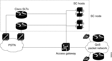
The SC node is the combination of hardware and software that provides the signaling controller function and transports the signaling traffic between the SC hosts and the SS7 signaling network. The SC node in the Cisco SS7 Interconnect for Voice Gateways Solution consists of one or more SC hosts, one or more Cisco SLTs, the signaling controller software, and ancillary equipment.
An SC host is a Sun hardware platform running signaling controller software.
Table 2-1 lists supported SC hosts for the Cisco SC2200 product.
| SC Host | Description |
|---|---|
Sun Netra t 112x | The Sun Netra t 112x is a general-purpose Sun Ultra SPARC server. The Sun Netra t 112x is rack-mountable and is NEBS and ETSI compliant. |
Sun Netra t 140x | The Sun Netra t 140x is a fault-tolerant, dual modular, redundant architecture. Additional lockstep operations give this host the ability to isolate and recover from hardware failure. |
The primary functions of the signaling controller is performing protocol conversion and call screening. The signaling controller is responsible for:
Table 2-2 lists the features for the SC hosts.
| Feature | Support for ... | ||
|---|---|---|---|
Call performance per signaling controller (simplex configuration with 20 minute call hold time) |
| ||
Call performance per signaling controller (continuous service configuration) |
| ||
Performance |
| ||
Signaling protocols |
| ||
Scaling of point codes | 250+ DPCs and 6 OPCs | ||
Network management interfaces | IP | ||
Faults and alarms management | SNMP traps | ||
Millisecond Timestamp | Millisecond time stamps on log records of diagnostic messages, set and clear alarm messages (sets and clears), alarm messages recorded by the Data Dumper, and alarm messages in the responses for the MML commands "rtrv-alms" and "rtrv-alms:CONT". | ||
Logging enhancements for Release 1.1 | Improved system logging efficiency and your ability to diagnose problems. The logging utility is enhanced in the following areas:
| ||
Configuration management |
| ||
Accounting | CDR (CSV format) support for international carrier requirements | ||
Resource management |
| ||
Performance measurements and statistics | Supports carrier requirements | ||
Security | Structured system of passwords | ||
Operating system | Sun Solaris 2.6.x | ||
Dial Plan Provisioning Enhancements | Enable you to input a shortest digit sequence to the Cisco SC2200 number analysis table to define a range of digit strings for the same digit analysis treatment. For example, for North America Numbering Plan (NANP) dial plans, the shortest digit sequence to identify the range of digit strings from 1-703-484-3000 through 1-703-484-3999 for the same digit analysis treatment would be 1-703-484-3 in the number analysis tables. | ||
MML-control of call processing resources | Provide a MML command interface to allow or reject any new calls. | ||
Route List Display | Display the symbolic name of a route list in the Telephony Controller Manager (TCM). | ||
Configuration Upload/Download | Provide new configuration management capabilities via both the SNMP and MML interfaces to upload or download all the non-static configuration information. | ||
MML Names in Log | Display component IDs in the terms of MML names in system logs. | ||
Bearer Channel Level Tracing | Provide a call tracing capability via the MML interface to generate machine-readable traces to be used by Call Trace Viewer (CTV) applications. | ||
Viewer Tools | Provide the following new viewing aids for system-generated data files:
| ||
Memory Reduction | Provide a per-call, post-answer memory reduction mechanism to accommodate 100,000 simultaneous calls on Cisco SC2200 with the Netra ft 1800 SC host.
|
The Cisco SS7 Interconnect for Voice Gateways Solution SC2200 product requires the following software release levels listed in Table 2-3.
| Software Release Level | Support for... |
|---|---|
Release 7.4 | Signaling controller software running on the SC host |
Release c2600-ipss7-mz | Software running on the Cisco SLT |
Cisco IOS Release 12.1(2)T or later releases | Cisco IOS release running on the access gateway |
Sun Solaris 2.6.x | Operating system running on the SC host |
The Cisco SLT handles the incoming and outgoing SS7 messages (MTP layer 1 and 2) that arrive from the PSTN Signal Transfer Points (STPs) or Service Switching Points (SSPs). When used in the proper configurations, the Cisco SLTs improve fault tolerance by providing for multiple communications paths between the SS7 signaling network and multiple SC hosts.
Table 2-4 lists the features for the Cisco SLT.
| Feature | Support for... |
|---|---|
SS7 link termination on a high-availability platform | SS7 network access and interconnection requires a high degree of reliability in the signaling links and associated equipment. The Cisco SLT provides the reliability of a dedicated signaling link termination device and maximizes the availability of the SS7 signaling links. |
Distributed SS7 MTP processing | Processor-intensive parts of the SS7 Message Transfer Part (levels1 and 2) are offloaded from the signaling controller to the Cisco SLT. This distributed MTP model allows the signaling controller to better utilize its resources to provide optimal call control. |
Call control | Signaling backhaul provides a means for integrating the signaling link terminals into a virtual switch with the call control intelligence centralized in the signaling controller system. |
Standard physical interfaces | Interconnection with SS7 network elements is supported using the most popular SS7 physical interface standards: T1, E1, V.35, EIA/TIA-449, and EIA/TIA-530. |
Drop and Insert | Cisco T1/E1 Multiflex Voice/WAN interface cards support Drop and Insert (also called TDM Cross-Connect), which allows individual T1/E1 channels to be transparently passed, uncompressed, between T1/E1 ports. This feature enables direct termination of SS7 F-links in T1 or E1 carriers, while the remaining bearer channels are hairpinned back to a gateway device for processing. |
The access gateway terminates the PSTN trunks, also referred to as bearer channels, that carry the call traffic. The PSTN trunks are T1 or E1 PRI interfaces. In addition, the access gateway performs call control (including originating and terminating call processing/signaling).
 |
Note Cisco IOS Release 12.0(7)XR or later releases run on the access gateway. |
Table 2-5 lists the features for the Cisco AS5x00.
| Feature | Support for... |
|---|---|
Continuity testing | Automated diagnostic procedure |
Redundant Link Manager | Virtual link management |
The control signaling network for the Cisco SS7 Interconnect for Voice Gateways Solution often consists of a LAN switch and the cabling required to interconnect the solution components in an SC zone. This solution supports a LAN switch from the Cisco Catalyst switch family. This switch can extend VLANs across platforms through backbone Fast Ethernet, Gigabit, or ATM connections, when necessary.
 |
Note The Catalyst LAN switch is not provided with the Cisco SC2200 product. |
![]()
![]()
![]()
![]()
![]()
![]()
![]()
![]()
Posted: Wed Sep 6 08:19:40 PDT 2000
Copyright 1989-2000©Cisco Systems Inc.