|
|

SS7 is a set of standards for the Common Channel Signaling (CCS) system. Historically, SS7 defines the architecture, network elements, interfaces, protocols, and management procedures for a Public Switched Telephone Network (PSTN) that transports control information between network switches and between switches and databases. SS7 is used between the PSTN switches; replacing per-trunk, in-band signaling.
Typically, SS7 is implemented on a separate data network within the PSTN and provides call setup and teardown, network management, fault resolution, and traffic management services. The SS7 network is used solely for network control, and the only data sent over it is signaling messages. (Note that the term SS7 can be used to refer to the SS7 protocol, the signaling network, or the signaling network architecture.)
The SS7 protocols that convey signaling information between switching systems (called signaling points) in the PSTN are carried on a special overlay network used exclusively for signaling. The signaling points use routing information in the SS7 signals to transfer calls to their final destinations.
The SS7 network features include:
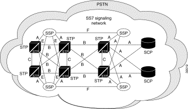
Figure A-1 is a graphic representation of SS7 links and how they are used in an SS7 signaling network.

The SS7 architecture consists of the following signaling points (as shown in Figure A-1):
As you can see in Figure A-1, the SCPs and STPs and their links are deployed as mated pairs because of the critical nature of the signaling network.
Each signaling point (also called an SS7 node or SP) in the SS7 network is identified with a unique address called a point code (PC). ANSI point codes are 24-bit and ITU point codes are 14-bit. PCs are carried in signaling messages exchanged between signaling points to identify the source and destination of each message. PCs are managed by the government agency that supervises, licenses, and controls electronic and electromagnetic transmission standards in your country. Note that there could be two separate agencies managing policy and providing licenses in your country.
 |
Note When using STPs, multiple signaling links between the same nodes (point-to-point) share traffic and are referred to as linksets. |
The ANSI point code is a hierarchical address consisting of:

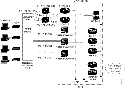
In Figure A-2, C-links (cross links) connect STPs together to form mated pairs (PC 171-016-000 and PC 171-001-000). A-links (access links) connect STPs with the telephone exchange signaling point (PC 171-001-003) and with the redundant pair of Cisco SLTs of the Cisco MGC signaling point.
 |
Note These point codes are in ANSI SS7 point code format. Variations of SS7 might use different point code formats. The network-cluster-member format is only valid with ANSI SS7 point code formats. |
The PC 171-016-000 used for one of the mated STPs consists of the following elements:
See the following publications and web site for a comprehensive overview of SS7:
![]()
![]()
![]()
![]()
![]()
![]()
![]()
![]()
Posted: Wed Sep 6 08:19:07 PDT 2000
Copyright 1989-2000©Cisco Systems Inc.