|
|

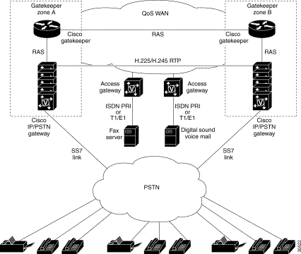
The Cisco SS7 Interconnect for Voice Gateways Solution builds on existing Cisco H.323 Voice over IP (VoIP) architecture that consists of a Cisco AS5x00 access gateway and Cisco 2600 or 3600 series routers operating as gatekeepers within an H.323 infrastructure. This architecture provides the quality of service (QoS), stability, and functionality necessary for carrier class, real-time IP communications services.
Figure B-1 illustrates the gateway and gatekeeper internetworking functionality in detail.

It helps to understand what happens at an application level when you place a call using VoIP. The general flow of a two-stage voice call using VoIP is as follows:
Step 2 The SSP provides digit analysis and route determination, then generates dial tone and sends an IAM to the signaling application part of VoIP in the gateway.
Step 3 The VoIP issues an alerting/ACM that indicates to the SSP to start the dial tone or busy tone (based on the state of the receiving end).
Step 4 Upon dial tone, the user dials the telephone number; those numbers are accumulated and stored by the session application.
Step 5 After enough digits are accumulated to match a configured destination pattern, the telephone number is mapped to an IP host through the dial plan mapper. The IP host has a direct connection to either the destination telephone number or a PBX that is responsible for completing the call to the configured destination pattern.
Step 6 The session application then runs the H.323 session protocol to establish a transmission and a reception channel for each direction over the IP network. If the call is being handled by a PBX, the PBX forwards the call to the destination telephone. If Resource Reservation Protocol (RSVP) has been configured, the RSVP reservations are put into effect to achieve the desired quality of service (QoS) over the IP network.
Step 7 The codecs are enabled for both ends of the connection and the conversation proceeds using RTP/UDP/IP as the protocol stack.
Step 8 Any call-progress indications (or other signals that can be carried in-band) are cut through the voice path as soon as an end-to-end audio channel is established. Signaling that can be detected by the voice ports (for example, in-band dual tone multifrequency [DTMF] digits after the call setup is complete) is also trapped by the session application at either end of the connection and carried over the IP network encapsulated in RTP Control Protocol (RTCP), using the RTCP APP extension mechanism.
Step 9 When either end of the call hangs up, the RSVP reservations are torn down (if RSVP is used) and the session ends. Each end becomes idle, waiting for the next off-hook condition to trigger another call setup.
The key elements of the H.323 VoIP architecture are:
In the Cisco H.323 VoIP with SS7 Solution, the Cisco AS5300 operates as the VoIP gateway and dial-up remote access server. When equipped with voice feature cards (VFCs) and voice-enabled Cisco IOS software the Cisco AS5300 supports carrier-class VoIP and fax over IP services.
Gateways allow H.323 terminals and routers to communicate with terminals running other protocols. They provide protocol conversion between terminals and routers running different types of protocols. A gateway is the point at which a circuit-switched call is encoded and repackaged into IP packets.
An H.323 gateway is an endpoint on the LAN that provides real-time, two-way communications between H.323 terminals on the LAN and other H.323 terminals in the WAN, or to another H.323 gateway.
A VoIP gateway has two primary applications. It can terminate a call from the PSTN and provide user admission control using integrated voice response (IVR) and provide accounting records for the call. The gateway also can direct the call to the destination or can terminate the call from another gateway and send the call to the PSTN. The gateway (in this document) refers to the voice-capable platform with voice cards and the VoIP image.
Figure B-2 and Figure B-3 illustrate these two applications. The VoIP gateway used in this solution is the Cisco AS5300.
Gatekeepers are optional nodes that manage other nodes in an H.323 network. Other nodes communicate with the gatekeeper using the Registration, Admission, and Status (RAS) protocol.
These nodes register with a gatekeeper on startup. When they wish to communicate with another endpoint, they request admission to the call, using a symbolic alias for the endpoint name, such as an E.164 address or an e-mail ID. If the gatekeeper decides that the call can proceed, it returns a destination IP address to the originating endpoint. This IP address can be the actual address of the target endpoint, or it can be an intermediate address. Finally, a gatekeeper and its registered endpoints exchange status information.
H.323 endpoints are grouped together in zones. Each zone has one gatekeeper that manages all of the endpoints in the zone. A zone is an administrative convenience similar to a DNS domain.
An H.323 terminal is an endpoint in the LAN that provides for real-time, two-way communications with another H.323 terminal or gateway. This communication consists of control, indications, audio, moving color video pictures, or data between the two terminals. A terminal may provide audio only; audio and data; audio and video; or audio, data, and video.
See the following publications for detailed information:
![]()
![]()
![]()
![]()
![]()
![]()
![]()
![]()
Posted: Wed Sep 6 08:19:04 PDT 2000
Copyright 1989-2000©Cisco Systems Inc.